- Using the EXEC Command Interpreter
- PA-A6 Configurations
- Shutting Down an Interface
- Performing a Basic Interface Configuration
- Configuring the PA-A6 for T3
- Configuring the PA-A6 for E3
- Configuring the PA-A6 for OC-3c
- Configuring VCs
- Configuring PVCs
- Configuring SVCs
- Configuring Classical IP and ARP over ATM
- Classes of Service and Transmit Priority on the PA-A6
- Customizing the PA-A6
- Checking the Configuration
- Traffic Management
- Troubleshooting the PA-A6 Installation and Configuration
- ATM Configuration
- Upgrading Your Boot Flash Image
- Port Adapter Error Messages
Configuring the PA-A6
To continue your port adapter installation, you must configure the ATM interfaces. The instructions that follow apply to all supported platforms. Minor differences among the platforms—with Cisco IOS software commands—are noted.
This chapter contains the following sections:
•![]() Using the EXEC Command Interpreter
Using the EXEC Command Interpreter
•![]() Troubleshooting the PA-A6 Installation and Configuration
Troubleshooting the PA-A6 Installation and Configuration
•![]() Upgrading Your Boot Flash Image
Upgrading Your Boot Flash Image
Using the EXEC Command Interpreter
You modify the configuration of your router through the software command interpreter called the EXEC (also called enable mode).
You must enter the privileged level of the EXEC command interpreter with the enable command before you can use the configure command to configure a new interface or change the existing interface configuration. The system prompts you for a password if one has been set. The system prompt for the privileged level ends with a pound sign (#) instead of an angle bracket (>).
At the console terminal, use the following procedure to enter the privileged level:
Step 1 ![]() At the user-level EXEC prompt, enter the enable command. The EXEC prompts you for a privileged-level password as follows:
At the user-level EXEC prompt, enter the enable command. The EXEC prompts you for a privileged-level password as follows:
Router> enable
Password:
Step 2 ![]() Enter the password (the password is case sensitive). For security purposes, the password is not displayed. When you enter the correct password, the system displays the privileged-level system prompt (#):
Enter the password (the password is case sensitive). For security purposes, the password is not displayed. When you enter the correct password, the system displays the privileged-level system prompt (#):
Router#
PA-A6 Configurations
After you verify that the PA-A6 is installed correctly (the ENABLED LED goes on), use the privileged-level configure command to configure the new interfaces. Have the following information available:
•![]() Protocols you plan to route on each new interface
Protocols you plan to route on each new interface
•![]() IP addresses, if you plan to configure the interfaces for IP routing
IP addresses, if you plan to configure the interfaces for IP routing
•![]() Bridging protocols you plan to use
Bridging protocols you plan to use
If you installed a new PA-A6 or if you want to change the configuration of an existing interface, you must enter configuration mode to configure the new interfaces. If you replaced a PA-A6 that was previously configured, the system recognizes the new interfaces and brings each of them up in their existing configurations.
For a summary of the configuration options available and instructions for configuring interfaces on a PA-A6, refer to the appropriate configuration publications listed in the "Related Documentation" section on page ix.
When an interface is enabled (taken out of shutdown mode) with no additional arguments, the default interface configuration file parameters are functional.
You execute configuration commands from the privileged level of the EXEC command interpreter, which usually requires password access. Contact your system administrator, if necessary, to obtain password access. (See the "Using the EXEC Command Interpreter" section for an explanation of the privileged level of the EXEC.)
This section contains the following configuration subsections for the standard configuration tasks:
•![]() Performing a Basic Interface Configuration
Performing a Basic Interface Configuration
•![]() Configuring the PA-A6 for OC-3c
Configuring the PA-A6 for OC-3c
•![]() Configuring Classical IP and ARP over ATM
Configuring Classical IP and ARP over ATM
•![]() Classes of Service and Transmit Priority on the PA-A6
Classes of Service and Transmit Priority on the PA-A6
Shutting Down an Interface
Before you remove an interface that you will not replace, replace interface cables, or replace port adapters, use the shutdown command to shut down (disable) the interfaces to prevent anomalies when you reinstall the new port adapter or reconfigured port adapter. When you shut down an interface, it is designated administratively down in the show command displays.
Follow these steps to shut down an interface:
Step 1 ![]() Enter the privileged level of the EXEC command interpreter (also called enable mode). (See the "Using the EXEC Command Interpreter" section for instructions.)
Enter the privileged level of the EXEC command interpreter (also called enable mode). (See the "Using the EXEC Command Interpreter" section for instructions.)
Step 2 ![]() At the privileged-level prompt, enter configuration mode and specify that the console terminal is the source of the configuration subcommands, as follows:
At the privileged-level prompt, enter configuration mode and specify that the console terminal is the source of the configuration subcommands, as follows:
Router# configure terminal
Enter configuration commands, one per line. End with CNTL/Z.
Router(config)#
Step 3 ![]() Shut down interfaces by entering the interface command (followed by the interface type and the interface address of the interface), and then enter the shutdown command. See "Using the show interfaces Command" section for the command syntax.
Shut down interfaces by entering the interface command (followed by the interface type and the interface address of the interface), and then enter the shutdown command. See "Using the show interfaces Command" section for the command syntax.
When you have finished, press Ctrl-Z—hold down the Control key while you press Z—or enter end or exit to exit configuration mode and return to the EXEC command interpreter.

Note ![]() If you need to shut down additional interfaces, enter the interface command (followed by the interface type and the interface address of the interface) for each of the interfaces on your port adapter. Use the no shutdown command to enable the interface.
If you need to shut down additional interfaces, enter the interface command (followed by the interface type and the interface address of the interface) for each of the interfaces on your port adapter. Use the no shutdown command to enable the interface.
Step 4 ![]() Write the new configuration to NVRAM as follows:
Write the new configuration to NVRAM as follows:
Router# copy running-config startup-config
[OK]
Router#
The system displays an OK message when the configuration has been stored in NVRAM.
Step 5 ![]() Verify that new interfaces are now in the correct state (shut down) using the show interfaces command (followed by the interface type and the interface address of the interface) to display the specific interface. The "Using the show interfaces Command" section provides examples.
Verify that new interfaces are now in the correct state (shut down) using the show interfaces command (followed by the interface type and the interface address of the interface) to display the specific interface. The "Using the show interfaces Command" section provides examples.
Step 6 ![]() Re-enable interfaces by doing the following:
Re-enable interfaces by doing the following:
a. ![]() Repeat Step 3 to re-enable an interface. Substitute the no shutdown command for the shutdown command.
Repeat Step 3 to re-enable an interface. Substitute the no shutdown command for the shutdown command.
b. ![]() Repeat Step 4 to write the new configuration to memory. Use the copy running-config startup-config command.
Repeat Step 4 to write the new configuration to memory. Use the copy running-config startup-config command.
c. ![]() Repeat Step 5 to verify that the interfaces are in the correct state. Use the show interfaces command followed by the interface type and interface address of the interface.
Repeat Step 5 to verify that the interfaces are in the correct state. Use the show interfaces command followed by the interface type and interface address of the interface.
For complete descriptions of software configuration commands, refer to the publications listed in the "Related Documentation" section on page ix.
Performing a Basic Interface Configuration
Following are instructions for a basic configuration, which include enabling an interface and specifying IP routing. You might also need to enter other configuration subcommands, depending on the requirements for your system configuration and the protocols you plan to route on the interface. For complete descriptions of configuration subcommands and the configuration options, refer to the appropriate software documentation.
In the following procedure, press the Return key after each step unless otherwise noted. At any time you can exit the privileged level and return to the user level by entering disable at the prompt as follows:
Router# disable
Router>
Step 1 ![]() Enter configuration mode and specify that the console terminal is the source of the configuration subcommands, as follows:
Enter configuration mode and specify that the console terminal is the source of the configuration subcommands, as follows:
Router# configure terminal
Enter configuration commands, one per line. End with CNTL/Z.
Router(config)#
Step 2 ![]() Specify the first interface to configure by entering the interface command, followed by the type of interface and the interface address of the interface you plan to configure. (The command for your port adapter will be specific to the technology of your interface.) The "Using the show interfaces Command" section provides examples.
Specify the first interface to configure by entering the interface command, followed by the type of interface and the interface address of the interface you plan to configure. (The command for your port adapter will be specific to the technology of your interface.) The "Using the show interfaces Command" section provides examples.
Step 3 ![]() Assign an IP address and subnet mask to the interface (if IP routing is enabled on the system) by using the ip address subcommand, as in the following example:
Assign an IP address and subnet mask to the interface (if IP routing is enabled on the system) by using the ip address subcommand, as in the following example:
Router(config-if)# ip address 10.0.0.0 10.255.255.255
Step 4 ![]() Add any additional configuration subcommands required to enable routing protocols and set the interface characteristics.
Add any additional configuration subcommands required to enable routing protocols and set the interface characteristics.
Step 5 ![]() Re-enable the interfaces using the no shutdown command. (See the "Shutting Down an Interface" section.)
Re-enable the interfaces using the no shutdown command. (See the "Shutting Down an Interface" section.)
Step 6 ![]() After including all of the configuration subcommands to complete your configuration, press Ctrl-Z—hold down the Control key while you press Z—or enter end or exit to exit configuration mode and return to the EXEC command interpreter prompt.
After including all of the configuration subcommands to complete your configuration, press Ctrl-Z—hold down the Control key while you press Z—or enter end or exit to exit configuration mode and return to the EXEC command interpreter prompt.
Step 7 ![]() Write the new configuration to NVRAM as follows:
Write the new configuration to NVRAM as follows:
Router# copy running-config startup-config
[OK]
Router#
The system displays an OK message when the configuration has been stored in NVRAM.
Note ![]() If you are going to disconnect or reconfigure the ATM interface cable, use the shutdown command before doing so. After reattaching the ATM interface cable, use the no shutdown command to bring up the ATM interface.
If you are going to disconnect or reconfigure the ATM interface cable, use the shutdown command before doing so. After reattaching the ATM interface cable, use the no shutdown command to bring up the ATM interface.
Configuring the PA-A6 for T3
To configure the PA-A6 for T3, perform the following tasks in interface configuration mode:
Step 1 ![]() Specify an ATM interface to configure. For the appropriate interface address to use for your system, refer to the "Identifying Interface Addresses" section on page 1-24.
Specify an ATM interface to configure. For the appropriate interface address to use for your system, refer to the "Identifying Interface Addresses" section on page 1-24.
Router# interface atm slot/port or slot/port-adapter/port
Step 2 ![]() Set the line build-out length (0 to 50 feet is short and greater than 50 feet is long). Use the no form of this command to return to the default, which is short.
Set the line build-out length (0 to 50 feet is short and greater than 50 feet is long). Use the no form of this command to return to the default, which is short.
Router(config-if)# lbo {short | long}
Step 3 ![]() Select the transmit clock source. This can be internal or derived from the receive clock through use of the no form of the command. By default, the receive clock source is used for the transmit clock.
Select the transmit clock source. This can be internal or derived from the receive clock through use of the no form of the command. By default, the receive clock source is used for the transmit clock.
Router(config-if)# clock internal
Step 4 ![]() Enable DS-3 scrambling. Use the no form of the command to restore the default value.
Enable DS-3 scrambling. Use the no form of the command to restore the default value.
Router(config-if)# DS3-scramble
Step 5 ![]() Specify DS-3 framing: m23plcp, cbitplcp, m23adm, or cbitadm. Use the no form of the command to return to the default, which is cbitadm.
Specify DS-3 framing: m23plcp, cbitplcp, m23adm, or cbitadm. Use the no form of the command to return to the default, which is cbitadm.
Router(config-if)# framing {m23plcp | cbitplcp | m23adm | cbitadm}
Configuring the PA-A6 for E3
To configure the PA-A6 for E3, perform the following tasks in interface configuration mode:
Step 1 ![]() Specify an ATM interface to configure. For the appropriate interface address to use for your system, refer to the "Identifying Interface Addresses" section on page 1-24.
Specify an ATM interface to configure. For the appropriate interface address to use for your system, refer to the "Identifying Interface Addresses" section on page 1-24.
Router# interface atm slot/port or slot/port-adapter/port
Step 2 ![]() Select the transmit clock source. This can be internal or derived from the receive clock through use of the no form of this command. By default, the source is used for the transmit clock.
Select the transmit clock source. This can be internal or derived from the receive clock through use of the no form of this command. By default, the source is used for the transmit clock.
Router(config-if)# clock internal
Step 3 ![]() Enable E3 scrambling. Use the no form of the command to restore the default value.
Enable E3 scrambling. Use the no form of the command to restore the default value.
Router(config-if)# e3-scramble
Step 4 ![]() Specify DS-3 framing: g832adm, g751adm, or g751plcp. Use the no form of the command to return to the default, which is g832adm.
Specify DS-3 framing: g832adm, g751adm, or g751plcp. Use the no form of the command to return to the default, which is g832adm.
Router(config-if)# framing {g832adm | g751adm | g751plcp}
Configuring the PA-A6 for OC-3c
To configure the PA-A6 for OC-3c, perform the following tasks in interface configuration mode:
Step 1 ![]() Specify an ATM interface to configure. For the appropriate interface address to use for your system, refer to the "Identifying Interface Addresses" section on page 1-24.
Specify an ATM interface to configure. For the appropriate interface address to use for your system, refer to the "Identifying Interface Addresses" section on page 1-24.
Router# interface atm slot/port or slot/port-adapter/port
Step 2 ![]() Select the transmit clock source. This can be internal or derived from the receive clock through use of the no form of this command. By default, the source is used for the transmit clock.
Select the transmit clock source. This can be internal or derived from the receive clock through use of the no form of this command. By default, the source is used for the transmit clock.
Router(config-if)# clock internal
Step 3 ![]() Specify SONET framing by using the sonet stm-1 command. Use the no form of this command to return to the default, STS-3c framing.
Specify SONET framing by using the sonet stm-1 command. Use the no form of this command to return to the default, STS-3c framing.
Router(config-if)# sonet stm-1
Note ![]() In ATM environments, the key difference between SONET and SDH framing modes is the type of cell transmitted when no user or data cells are available. The ATM forum specifies use of idle cells if unassigned cells are not generated. More specifically, in Synchronous Transport Module-X (STM-X) mode, an ATM interface sends idle cells for cell-rate decoupling. In Synchronous Transport Signal-Xc (STS-Xc) mode, the ATM interface sends unassigned cells for cell-rate decoupling.
In ATM environments, the key difference between SONET and SDH framing modes is the type of cell transmitted when no user or data cells are available. The ATM forum specifies use of idle cells if unassigned cells are not generated. More specifically, in Synchronous Transport Module-X (STM-X) mode, an ATM interface sends idle cells for cell-rate decoupling. In Synchronous Transport Signal-Xc (STS-Xc) mode, the ATM interface sends unassigned cells for cell-rate decoupling.
Configuring VCs
A virtual circuit (VC) is a point-to-point connection between remote hosts and routers. A VC is established for each ATM end node with which the router communicates. The characteristics of the VC are established when the VC is created and include the following:
•![]() Class of service category:
Class of service category:
–![]() Constant bit rate (CBR)
Constant bit rate (CBR)
–![]() Non-real-time variable bit rate (nrt-VBR)
Non-real-time variable bit rate (nrt-VBR)
–![]() Real-time variable bit rate (rt-VBR)
Real-time variable bit rate (rt-VBR)
–![]() Available bit rate (ABR)
Available bit rate (ABR)
–![]() Unspecified bit rate (UBR)
Unspecified bit rate (UBR)
•![]() ATM adaptation layer 5 (AAL5)
ATM adaptation layer 5 (AAL5)
•![]() Encapsulation type:
Encapsulation type:
–![]() Logical link control Subnetwork Address Protocol (AAL5SNAP)
Logical link control Subnetwork Address Protocol (AAL5SNAP)
–![]() Multiplexer (AAL5MUX)
Multiplexer (AAL5MUX)
–![]() Network Layer Protocol ID (AAL5NLPID)
Network Layer Protocol ID (AAL5NLPID)
–![]() Integrated Local Management Interface (ILMI)
Integrated Local Management Interface (ILMI)
–![]() Switched Multimegabit Data Service (SMDS)
Switched Multimegabit Data Service (SMDS)
–![]() ITU/Q.2931 Signaling ATM Adaptation Layer (QSAAL)
ITU/Q.2931 Signaling ATM Adaptation Layer (QSAAL)
–![]() Cisco AUTO PPP over AAL5 (AAL5AUTOPPP)
Cisco AUTO PPP over AAL5 (AAL5AUTOPPP)
–![]() Cisco PPP over AAL5 (AAL5CISCOPPP)
Cisco PPP over AAL5 (AAL5CISCOPPP)
Note ![]() See the ATM virtual circuit configuration commands in the example output of the "Classes of Service and Transmit Priority on the PA-A6" section.
See the ATM virtual circuit configuration commands in the example output of the "Classes of Service and Transmit Priority on the PA-A6" section.
Each VC supports the following router functions:
•![]() Multiprotocol
Multiprotocol
•![]() Fast switching of IP packets
Fast switching of IP packets
•![]() Flow, and Cisco Express Forwarding (CEF) switching of IP packets
Flow, and Cisco Express Forwarding (CEF) switching of IP packets
•![]() Pseudobroadcast support for multicast packets
Pseudobroadcast support for multicast packets
By default, CEF switching is enabled on all PA-A6 interfaces. These switching features can be turned off with interface configuration commands. Flow must be explicitly enabled for each interface.
Configuring PVCs
To use a permanent virtual circuit (PVC), configure the PVC in both the router and the ATM switch. PVCs remain active until the circuit is removed from either configuration. When a PVC is configured, all of the configuration options are passed on to the PA-A6. You can write these PVCs into nonvolatile RAM (NVRAM); they are used when the system image is reloaded. Some ATM switches might have point-to-multipoint PVCs that do the equivalent of broadcasting. If a point-to-multipoint PVC exists, it can be used as the sole broadcast PVC for all multicast requests. Like Frame Relay, ATM supports two types of interface: point-to-point and multipoint. The one you choose determines whether you need to use the configuration commands that ensure IP to ATM mappings.
To configure a PVC, refer to the following sections:
•![]() Configuring a PVC on a Point-to-Point Subinterface
Configuring a PVC on a Point-to-Point Subinterface
•![]() Configuring a PVC on a Multipoint Subinterface
Configuring a PVC on a Multipoint Subinterface
Note ![]() Static map statements are not required for point-to-point subinterfaces.
Static map statements are not required for point-to-point subinterfaces.
Configuring a PVC on a Point-to-Point Subinterface
With point-to-point subinterfaces, each pair of routers has its own subnet. If you put the PVC on a point-to-point subinterface, the router assumes that there is only one point-to-point PVC configured on the subinterface. Therefore, any IP packets with a destination IP address in the same subnet are forwarded on this VC.
To configure a point-to-point PVC, perform the following tasks from configuration mode:
Step 1 ![]() Enter interface configuration mode and specify an ATM interface using the interface atm command. Specify the creation of a point-to-point interface by using the point command.
Enter interface configuration mode and specify an ATM interface using the interface atm command. Specify the creation of a point-to-point interface by using the point command.
Router(config)# interface atm5/0.200 point
Step 2 ![]() You can list the VPI and VCI values using the pvc ? command.
You can list the VPI and VCI values using the pvc ? command.
Router(config-if)# pvc ?
<0-255> Enter VPI/VCI value(slash required)
<1-65535> Enter VCI value
WORD Optional handle to refer to this connection
Step 3 ![]() Create the PVC. Notice the output telling you that circuit has been configured on a specific interface.
Create the PVC. Notice the output telling you that circuit has been configured on a specific interface.
Router(config-if)# pvc 1/1
Configuring vc 1/1 on interface ATM5/0.200
Router(config-if-atm-vc)#
Configuring a PVC on a Multipoint Subinterface
Multipoint networks generally have three or more routers in the same subnet. If you put the PVC in a point-to-multipoint subinterface or in the main interface (which is multipoint by default), you need to either configure static mapping or enable inverse Address Resolution Protocol (InARP) for dynamic mapping.
The following output example shows a PVC 2/200 on ATM interface 1/1/0.200. It uses the global default AAL5SNAP encapsulation. The local interface IP address is 2.2.2.1, and the remote interface IP address is 2.2.2.2.
Router# show interfaces atm 1/1/0.200
interface ATM1/1/0.200 multipoint
ip address 2.2.2.1 255.255.255.0
no ip directed-broadcast
pvc 2/200
protocol ip 2.2.2.2 broadcast
InARP is enabled on multipoint links by default. The following example shows a multipoint subinterface. By using the show atm map command, you can see that InARP builds a dynamic mapping between the Layer 3 IP address and the Layer 2 VPI/VCI:
Router# show atm map
Map list ATM1/1/0.100_ATM_INARP : DYNAMIC
ip 1.1.1.2 maps to VC 19, VPI 2, VCI 100, ATM1/1/0.100
Map list ATM1/1/0.200_ATM_INARP : DYNAMIC
ip 2.2.2.2 maps to VC 20, VPI 2, VCI 200, ATM1/1/0.200
You can check the mapping using the show atm map command. In the following example, you can see the mapping of Layer 3 to Layer 2 addresses is dynamic.
Router# show atm map
Map list ATM1/1/0.100_ATM_INARP : DYNAMIC
ip 1.1.1.2 maps to VC 19, VPI 2, VCI 100, ATM1/1/0.100
Map list ATM1/1/0.200pvc20 : PERMANENT
ip 2.2.2.2 maps to VC 20, VPI 2, VCI 200, ATM1/1/0.200, broadcast
You can use the inarp command to change the frequency of transmitting a new ATM InARP packet in order to reconfirm the mapping:
Router(config-subif)# pvc 2/200
Router(config-if-atm-vc)#inarp ?
<1-60> InARP Frequency in minutes
<cr>
Router(config-if-atm-vc)# inarp 5
Router(config-if-atm-vc)# end
You can use the show atm vc command to confirm your configured value:
Router# show atm vc
5d10h: ATMARP:Sending first PVC INARP
5d10h: ATMARP(ATM1/1/0.200)O: INARP_REQ to VCD#20 2/200 for link 7(IP)
5d10h: ATMARP(ATM1/1/0.200)I: INARP Reply VCD#20 2/200 from 2.2.2.2
ATM1/1/0.200: VCD: 20, VPI: 2, VCI: 200
UBR, PeakRate: 44209
AAL5-LLC/SNAP, etype:0x0, Flags: 0xC20, VCmode: 0x0
OAM frequency: 0 second(s)
InARP frequency: 5 minutes(s)
Transmit priority 4
InPkts: 10, OutPkts: 11, InBytes: 680, OutBytes: 708
InPRoc: 10, OutPRoc: 5, Broadcasts: 0
InFast: 0, OutFast: 0, InAS: 0, OutAS: 6
InPktDrops: 0, OutPktDrops: 0
CrcErrors: 0, SarTimeOuts: 0, OverSizedSDUs: 0
OAM cells received: 0
OAM cells sent: 0
Status: UP
Configuring SVCs
ATM switched virtual circuits (SVCs) are created and released dynamically, providing user bandwidth on demand. This service requires a signaling protocol between the router and the switch.
The ATM signaling software provides a method of dynamically establishing, maintaining, and clearing ATM connections at the User-Network Interface (UNI). The ATM signaling software conforms to the ATM Forum UNI 4.0 specification.
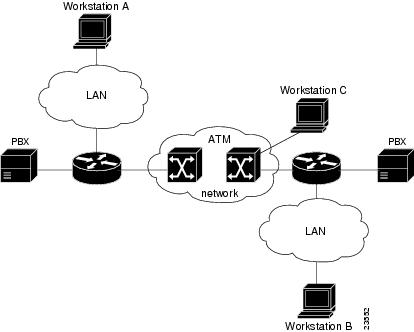
In UNI mode, the user is the router, and the network is an ATM switch. This is an important distinction. The Cisco router does not perform ATM-level call routing. Instead, the ATM switch does the ATM call routing, and the router routes packets through the resulting circuit. The router is viewed as the user and the LAN interconnection device at the end of the circuit, and the ATM switch is viewed as the network.
Figure 4-1 illustrates the router position in a basic ATM environment. The router is used primarily to interconnect LANs through an ATM network. Workstation C in Figure 4-1 is connected directly to the destination ATM switch. You can connect not only routers to ATM switches, but also any network device with an ATM interface that conforms to the ATM Forum UNI specification.
Figure 4-1 Basic ATM Environment
To use SVCs, complete the required tasks in the following sections:
•![]() Configuring the PVC That Performs SVC Call Setup
Configuring the PVC That Performs SVC Call Setup
•![]() Configuring the Network Service Access Point Address
Configuring the Network Service Access Point Address
Configuring the PVC That Performs SVC Call Setup
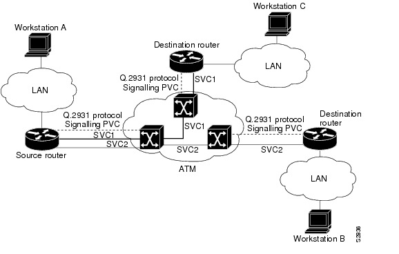
ATM uses out-of-band signaling. One dedicated PVC exists between the router and the ATM switch, over which all SVC call establishment and call termination requests flow. After the call is established, data transfer occurs over the SVC, from router to router. The signaling that accomplishes the call setup and teardown is called Layer 3 signaling or the Q.2931 protocol.
For out-of-band signaling, a signaling PVC must be configured before any SVCs can be set up. In Figure 4-2, a signaling PVC from the source router to the ATM switch is used to set up two SVCs. This is a fully meshed network; workstations A, B, and C can all communicate with one another.
Figure 4-2 One or More SVCs Require a Signaling PVC
To configure the signaling PVC for all SVC connections, enter the pvc vcd vpi vci qsaal command in interface configuration mode.
Note ![]() This signaling PVC can be set up on a major interface only, not on the subinterfaces.
This signaling PVC can be set up on a major interface only, not on the subinterfaces.
The VPI and VCI values must be configured consistently with the local switch. The standard value of VPI is 0, and the range of VPI values is 0 through 255. The standard value of VCI is 5, and the range of VCI values is 0 through 65535.
Note ![]() VCI values 0 through 31 are reserved and do not carry data traffic.
VCI values 0 through 31 are reserved and do not carry data traffic.
For further information on configuring the PA-A6 port adapter for SVCs, see the Cisco IOS Wide-Area Networking Configuration Guide, Release 12.2 at the following URL:
Configuring the Network Service Access Point Address
Every ATM interface involved with signaling must be configured with a network service access point (NSAP) address. The NSAP address is the ATM address of the interface and must be unique across the network.
To configure an NSAP address, complete the tasks in the following sections:
•![]() Configuring the Complete NSAP Address Manually
Configuring the Complete NSAP Address Manually
•![]() Configuring the ESI and Selector Fields
Configuring the ESI and Selector Fields
To configure the ESI and Selector fields, you must also configure a PVC to communicate with the switch through ILMI:
Router(config-if)# pvc 0/16 ilmi
The switch then provides the Prefix field of the NSAP address.
Configuring the Complete NSAP Address Manually
When you configure the NSAP address manually, you must enter the entire address in hexadecimal format; that is, each digit entered represents a hexadecimal digit. To represent the complete NSAP address, you must enter 40 hexadecimal digits in the following format:
XX.XXXX.XX.XXXXXX.XXXX.XXXX.XXXX.XXXX.XXXX.XXXX.XX
Note ![]() All NSAP addresses must be entered in the dotted hexadecimal format shown.
All NSAP addresses must be entered in the dotted hexadecimal format shown.
Because the interface has no default NSAP address, you must configure the NSAP address for SVCs. Use the nsap-address nsap-address command in interface configuration mode to set the ATM source NSAP address.
The following is an example of an NSAP address assigned to ATM interface 4/0 on a Cisco 7200 series router:
Router (config)# interface atm 4/0
Router (config-if)# nsap-address AB.CDEF.01.234567.890A.BCDE.F012.3456.7890.1234.12
You can display the ATM address for the interface by executing the show interfaces atm command.
Configuring the ESI and Selector Fields
You can configure the router to get the NSAP address prefix from the switch; however, the switch must be capable of delivering the NSAP address prefix to the router through ILMI, and the router must be configured with a PVC for communication with the switch through ILMI.
To configure the router to get the NSAP prefix from the switch and use locally entered values for the remaining fields of the address, complete the following tasks in interface configuration mode:
Step 1 ![]() Specify an ATM interface to configure.
Specify an ATM interface to configure.
Router(config)# interface atm slot/port or slot/port-adapter/port
Step 2 ![]() Enter the ESI and Selector fields of the NSAP address.
Enter the ESI and Selector fields of the NSAP address.
Router(config-if)# esi-address esi.selector
In the esi-address command, the esi argument is 6 hexadecimal bytes long (12 digits), and the selector argument is 1 hexadecimal byte long (2 digits).
In the following example on a Cisco 7200 series router, the ESI and Selector field values are assigned, and the ILMI PVC is set up:
Router(config)# interface atm 4/0
Router(config-if)# esi-address 345678901234.12
Configuring Classical IP and ARP over ATM
Cisco implements both the ATM Address Resolution Protocol (ARP) server and ATM ARP client functions described in RFC 1577. RFC 1577 models an ATM network as a logical IP subnetwork on a LAN.
The tasks required to configure classical IP and ARP over ATM depend on whether there are SVCs or PVCs present in the environment. For further information, refer to the Cisco IOS Wide-Area Networking Configuration Guide, Release 12.2 at the following URL:
Classes of Service and Transmit Priority on the PA-A6
The transmit priority determines which queued cell is chosen to be transmitted out an interface during a cell time slot and ensures that real-time ATM service classes, which typically offer more robust QoS and traffic guarantees, have a higher likelihood of access to the next cell time slot. Table 4-1 lists the ATM service classes and their default transmit priorities on the PA-A6.
Note ![]() Refer to the feature module documentation and Technical Tips on Cisco.com for detailed information about classes of service, configuration features, and the Cisco IOS releases that the support specific features.
Refer to the feature module documentation and Technical Tips on Cisco.com for detailed information about classes of service, configuration features, and the Cisco IOS releases that the support specific features.
Note ![]() Transmit priority 0 is reserved for control traffic like OAM and signaling.
Transmit priority 0 is reserved for control traffic like OAM and signaling.
You can use the transmit-priority command in VC configuration mode to change the priority value. The following example shows a customized prioritization scheme with the transmit priority value of a VC changed from 4 to 2.
Step 1 ![]() First, view the characteristics of the existing configuration using the show atm vc {vcd#} command. Note how the router has assigned a default transmit priority value of 5 to the UBR PVC:
First, view the characteristics of the existing configuration using the show atm vc {vcd#} command. Note how the router has assigned a default transmit priority value of 5 to the UBR PVC:
Router# show atm vc 2
ATM5/0: VCD: 2, VPI: 1, VCI: 100
UBR, PeakRate: 10000
AAL5-LLC/SNAP, etype:0x0, Flags: 0x20, VCmode: 0x0
OAM frequency: 0 second(s)
PA TxRingLimit: 0 paritcles
PA Rx Limit: 0 particles
InARP frequency: 15 minute(s)
Transmit priority 5
InPkts: 0, OutPkts: 0, InBytes: 0, OutBytes: 0
InPRoc: 0, OutPRoc: 0, Broadcasts: 0
InPktsDrops: 0, OutPktDrops: 0
CrcErrors: 0, SarTimeOuts: 0. OverSizedSDUs: 0
OAM cells received: 0
OAM cells sent:0
Status: ACTIVE
Step 2 ![]() Next, customize the transmit priority value from VC configuration mode.
Next, customize the transmit priority value from VC configuration mode.
Router(config)# interface atm 5/0
Router(config-if)# pvc x/100
Router(config-if-atm-vc)# transmit-priority 2
Step 3 ![]() The final action is to confirm your settings. Note how the router indicates the changed transmit priority level. It is now at level 2.
The final action is to confirm your settings. Note how the router indicates the changed transmit priority level. It is now at level 2.
Router# show atm vc 2
ATM5/0: VCD: 2, VPI: 1, VCI: 100
UBR, PeakRate: 10000
AAL5-LLC/SNAP, etype:0x0, Flags: 0x20, VCmode: 0x0
OAM frequency: 0 second(s)
PA TxRingLimit: 0 particles
PA Rx Limit: 0 particles
InARP frequency: 15 minute(s)
Transmit priority 2
InPkts: 0, OutPkts: 0, InBytes: 0, OutBytes: 0
InPRoc: 0, OutPRoc: 0, Broadcasts: 0
InPktsDrops: 0, OutPktDrops: 0
CrcErrors: 0, SarTimeOuts: 0. OverSizedSDUs: 0
OAM cells received: 0
OAM cells sent:0
Status: ACTIVE
Customizing the PA-A6
Depending on the requirements for your system and the protocols you plan to route on the interface, you might need to enter configuration commands to customize your system. If you need to customize your configuration, see the following procedures:
•![]() Configuring an ATM Interface for Local Loopback
Configuring an ATM Interface for Local Loopback
•![]() Configuring an ATM Interface for External Loopback
Configuring an ATM Interface for External Loopback
Note ![]() For the commands that follow, you need to be in interface configuration mode. To enter interface configuration mode, use the interface atm command, followed by the interface address of the ATM interface you plan to configure.
For the commands that follow, you need to be in interface configuration mode. To enter interface configuration mode, use the interface atm command, followed by the interface address of the ATM interface you plan to configure.
Setting the MTU Size
Each ATM interface has a default maximum packet size or maximum transmission unit (MTU) size. On the PA-A6, this number defaults to 4470 bytes, the range being 64 through 9188 bytes. To set the maximum MTU size, enter the following command in interface configuration mode:
Router(config-if)# mtu bytes
Note ![]() This command is documented in the Cisco IOS Configuration Fundamentals Command Reference, Release 12.2 at the following URL:
This command is documented in the Cisco IOS Configuration Fundamentals Command Reference, Release 12.2 at the following URL:
http://www.cisco.com/en/US/products/sw/iosswrel/ps1835/products_command_reference_book09186a00800811e0.html
Configuring an ATM Interface for Local Loopback
To configure an ATM interface for local loopback (useful for checking that the PA-A6 is working by looping the transmit data back to the receive data), use the following command:
Router(config-if)# loopback diagnostic
The no form of the command turns off local loopback:
Router(config-if)# no loopback diagnostic
Configuring an ATM Interface for External Loopback
To configure an ATM interface for external loopback (useful for checking that the PA-A6 is working by looping the receive data back to the transmit data), use the following command:
Router(config-if)# loopback line
The no form of the command turns off external loopback:
Router(config-if)# no loopback line
Checking the Configuration
After configuring the new interface, use the show commands to display the status of the new interface or all interfaces, and use the ping and loopback commands to check connectivity. This section includes the following subsections:
•![]() Using show Commands to Verify the New Interface Status
Using show Commands to Verify the New Interface Status
•![]() Using the ping Command to Verify Network Connectivity
Using the ping Command to Verify Network Connectivity
Using show Commands to Verify the New Interface Status
This section demonstrates how you can use the show commands to verify that new interfaces are configured and operating correctly and that the port adapter appears in them correctly. Sample displays of the output of selected show commands appear in the sections that follow. For complete command descriptions and examples, refer to the publications listed in the "Related Documentation" section on page ix.
If an interface is shut down and you configured it as up, or if the displays indicate that the hardware is not functioning properly, ensure that the interface is properly connected and terminated. If you still have problems bringing up the interface, contact a service representative for assistance. This section includes the following subsections:
•![]() Using the show version or show hardware Commands
Using the show version or show hardware Commands
•![]() Using the show interfaces Command
Using the show interfaces Command
Using the show version or show hardware Commands
Display the configuration of the system hardware, the number of each interface type installed, the Cisco IOS software version, the names and sources of configuration files, and the boot images using the show version (or show hardware) command.
Note ![]() The outputs that appear in this document may not match the output you receive when running these commands. The outputs in this document are examples only.
The outputs that appear in this document may not match the output you receive when running these commands. The outputs in this document are examples only.
The following sections provide platform-specific output examples using the show version command:
•![]() Cisco 7200 Series Routers and Cisco 7200 VXR Routers—Example Output of the show version Command
Cisco 7200 Series Routers and Cisco 7200 VXR Routers—Example Output of the show version Command
•![]() Cisco 7201 Router—Example Output of the show version Command
Cisco 7201 Router—Example Output of the show version Command
•![]() Cisco 7301 Router—Example Output of the show version Command
Cisco 7301 Router—Example Output of the show version Command
•![]() Cisco 7401ASR Router—Example Output of the show version Command
Cisco 7401ASR Router—Example Output of the show version Command
•![]() Cisco 7500 Series Routers—Example Output of the show version Command
Cisco 7500 Series Routers—Example Output of the show version Command
•![]() Cisco 7600 Series Routers—Example Output of the show version Command
Cisco 7600 Series Routers—Example Output of the show version Command
Cisco 7200 Series Routers and Cisco 7200 VXR Routers—Example Output of the show version Command
Following is an example of the show version command from a Cisco 7200 series router:
Router# show version
Cisco Internetwork Operating System Software
IOS (tm) 7200 Software (C7200-IS-M), Version 12.2(8)B, RELEASE SOFTWARE (fc1)
TAC Support: http://www.cisco.com/tac
Copyright (c) 1986-2002 by cisco Systems, Inc.
Compiled Fri 02-Aug-02 10:51 by ccai
Image text-base: 0x60008940, data-base: 0x61850000
ROM: System Bootstrap, Version 11.1(13)CA, EARLY DEPLOYMENT RELEASE SOFTWARE (f)
BOOTLDR: 7200 Software (C7200-BOOT-M), Version 11.1(16)CA, EARLY DEPLOYMENT REL
d11-5-7206-15 uptime is 1 week, 31 minutes
System returned to ROM by reload at 14:08:34 UTC Tue Aug 20 2002
System image file is "slot0:c7200-is-mz.122-11.T"
cisco 7206 (NPE200) processor (revision B) with 114688K/16384K bytes of memory.
Processor board ID 15455885
R5000 CPU at 200Mhz, Implementation 35, Rev 2.1, 512KB L2 Cache
6 slot midplane, Version 1.3
Last reset from power-on
Bridging software.
X.25 software, Version 3.0.0.
Primary Rate ISDN software, Version 1.1.
1 FastEthernet/IEEE 802.3 interface(s)
2 Serial network interface(s)
2 HSSI network interface(s)
11 ATM network interface(s)
4 Channelized T1/PRI port(s)
125K bytes of non-volatile configuration memory.
4096K bytes of packet SRAM memory.
20480K bytes of Flash PCMCIA card at slot 0 (Sector size 128K).
4096K bytes of Flash internal SIMM (Sector size 256K).
Configuration register is 0x2102
Cisco 7201 Router—Example Output of the show version Command
Following is an example of the show version command from a Cisco 7201 router:
Router# show version
Cisco IOS Software, 7200 Software (C7200P-ADVENTERPRISEK9-M), Version
12.4(biffDEV.061001), INTERIM SOFTWARE Copyright (c) 1986-2006 by Cisco Systems, Inc.
Compiled Sun 01-Oct-06 23:42 by biff
ROM: System Bootstrap, Version 12.4(4r)XD5, RELEASE SOFTWARE (fc1)
BOOTLDR: Cisco IOS Software, 7200 Software (C7200P-KBOOT-M), Version 12.4(TAZ3DEV.060927),
INTERIM SOFTWARE
c7201alpha1 uptime is 5 days, 18 hours, 32 minutes System returned to ROM by power-on
System image file is "disk0:c7200p-adventerprisek9-mz.2006-10-01.biffdev"
This product contains cryptographic features and is subject to United States and local
country laws governing import, export, transfer and use. Delivery of Cisco cryptographic
products does not imply third-party authority to import, export, distribute or use
encryption.
Importers, exporters, distributors and users are responsible for compliance with U.S. and
local country laws. By using this product you agree to comply with applicable laws and
regulations. If you are unable to comply with U.S. and local laws, return this product
immediately.
A summary of U.S. laws governing Cisco cryptographic products may be found at:
http://www.cisco.com/wwl/export/crypto/tool/stqrg.html
If you require further assistance please contact us by sending email to export@cisco.com.
Cisco 7201 (c7201) processor (revision A) with 917504K/65536K bytes of memory.
Processor board ID 2222222222222
MPC7448 CPU at 1666Mhz, Implementation 0, Rev 2.2
1 slot midplane, Version 2.255
Last reset from power-on
1 FastEthernet interface
4 Gigabit Ethernet interfaces
2045K bytes of NVRAM.
62443K bytes of USB Flash usbflash0 (Read/Write)
250880K bytes of ATA PCMCIA card at slot 0 (Sector size 512 bytes).
65536K bytes of Flash internal SIMM (Sector size 512K).
Configuration register is 0x2
Cisco 7301 Router—Example Output of the show version Command
Following is an example of the show version command from a Cisco 7301 router:
Router# show version
Cisco Internetwork Operating System Software
IOS (tm) 7301 Software (C7301-JS-M), Version 12.3(8.4), MAINTENANCE INTERIM SOFTWARE
Copyright (c) 1986-2004 by cisco Systems, Inc.
Compiled Thu 22-Apr-04 01:28 by kellythw
Image text-base: 0x60008AF4, data-base: 0x61F88000
ROM: System Bootstrap, Version 12.2(8r)B3, RELEASE SOFTWARE (fc1)
BOOTLDR: 7301 Software (C7301-BOOT-M), Version 12.2(18)S, EARLY DEPLOYMENT RELEASE
SOFTWARE (fc1)
7301A-2 uptime is 3 days, 18 hours, 16 minutes
System returned to ROM by power-on
System image file is "disk0:c7301-js-mz.123-8.4"
cisco 7301 (NPE) processor (revision A) with 983040K/65536K bytes of memory.
Processor board ID 74804651
SB-1 CPU at 700MHz, Implementation 1, Rev 0.2, 512KB L2 Cache
1 slot midplane, Version 2.0
Last reset from power-on
Bridging software.
X.25 software, Version 3.0.0.
SuperLAT software (copyright 1990 by Meridian Technology Corp).
TN3270 Emulation software.
3 Gigabit Ethernet/IEEE 802.3 interface(s)
1 ATM network interface(s)
509K bytes of non-volatile configuration memory.
62976K bytes of ATA PCMCIA card at slot 0 (Sector size 512 bytes).
32768K bytes of Flash internal SIMM (Sector size 256K).
Configuration register is 0x2102
Cisco 7401ASR Router—Example Output of the show version Command
Following is an example of the show version command from a Cisco 7401ASR router:
Router# show version
Cisco Internetwork Operating System Software
IOS (tm) 7400 Software (C7400-JS-M), Version 12.2(15)B, EARLY DEPLOYMENT RELEASE SOFTWARE
(fc1)
TAC Support: http://www.cisco.com/tac
Copyright (c) 1986-2003 by cisco Systems, Inc.
Compiled Fri 31-Jan-03 03:11 by leccese
Image text-base: 0x60008954, data-base: 0x61EEE000
ROM: System Bootstrap, Version 12.2(4r)B1, RELEASE SOFTWARE (fc1)
BOOTLDR: 7400 Software (C7400-KBOOT-M), Version 12.2(1)DX, EARLY DEPLOYMENT RELEASE
SOFTWARE (fc1)
7401A-1 uptime is 4 minutes
System returned to ROM by reload at 19:48:53 UTC Mon May 17 2004
System image file is "disk0:c7400-js-mz.122-15.B"
cisco 7401ASR (NSE) processor (revision A) with 491520K/32768K bytes of memory.
Processor board ID 74994942
R7000 CPU at 375Mhz, Implementation 39, Rev 3.3, 256KB L2, 2000KB L3 Cache
1 slot ASR midplane, Version 2.0
Last reset from power-on
Bridging software.
X.25 software, Version 3.0.0.
SuperLAT software (copyright 1990 by Meridian Technology Corp).
TN3270 Emulation software.
PXF processor tmc is running.
2 Gigabit Ethernet/IEEE 802.3 interface(s)
1 ATM network interface(s)
509K bytes of non-volatile configuration memory.
125440K bytes of ATA PCMCIA card at slot 0 (Sector size 512 bytes).
8192K bytes of Flash internal SIMM (Sector size 256K).
Configuration register is 0x2102
Cisco 7500 Series Routers—Example Output of the show version Command
Following is an example of the show version command from a Cisco 7500 series router:
Router# show version
Cisco Internetwork Operating System Software
IOS (tm) RSP Software (RSP-PV-M), Version 12.0(19991214:220504)
[den 160]
Copyright (c) 1986-2004 by cisco Systems, Inc.
Compiled Wed 12-Jan-00 15:42 by biff
Image text-base:0x60010900, data-base:0x60C40000
ROM:System Bootstrap, Version 11.1(8)CA1,
(fc1)
Router uptime is 10 minutes
System returned to ROM by reload at 15:05:17 UTC Sun Aug 15 1999
System image file is "slot0:rsp-pv-mz.cfg1-noABR-322_a1_0112"
cisco RSP4 (R5000) processor with 65536K/2072K bytes of memory.
R5000 CPU at 200Mhz, Implementation 35, Rev 2.1, 512KB L2 Cache
Last reset from power-on
G.703/E1 software, Version 1.0.
G.703/JT2 software, Version 1.0.
X.25 software, Version 3.0.0.
Chassis Interface.
1 EIP controller (6 Ethernet).
4 VIP2 R5K controllers (1 ATM)(3 POS).
1 VIP4 RM7000 controller (1 ATM).
6 Ethernet/IEEE 802.3 interface(s)
2 ATM network interface(s)
3 Packet over SONET network interface(s)
123K bytes of non-volatile configuration memory.
20480K bytes of Flash PCMCIA card at slot 0 (Sector size 128K).
8192K bytes of Flash PCMCIA card at slot 1 (Sector size 128K).
8192K bytes of Flash internal SIMM (Sector size 256K).
No slave installed in slot 7.
Configuration register is 0x0
Cisco 7600 Series Routers—Example Output of the show version Command
Following is an example of the show version command from a Cisco 7600 series router:
Router# show version
Cisco Internetwork Operating System Software
IOS (tm) MSFC Software (C6MSFC-JSV-M), Version 12.1(20010119:22010]
Copyright (c) 1986-2001 by cisco Systems, Inc.
Compiled Fri 19-Jan-01 14:46 by biff
Image text-base: 0x60008950, data-base: 0x617AC000
ROM: System Bootstrap, Version 12.0(3)XE, RELEASE SOFTWARE
BOOTFLASH: MSFC Software (C6MSFC-BOOT-M), Version 12.0(7)XE1, EARLY DEPLOYMENT )
Switch uptime is 4 hours, 21 minutes
System returned to ROM by reload
System image file is "bootflash:c6msfc-jsv-mz.Feb9"
cisco Cat6k-MSFC (R5000) processor with 114688K/16384K bytes of memory.
Processor board ID SAD03432638
R5000 CPU at 200Mhz, Implementation 35, Rev 2.1, 512KB L2 Cache
Last reset from power-on
Bridging software.
X.25 software, Version 3.0.0.
SuperLAT software (copyright 1990 by Meridian Technology Corp).
TN3270 Emulation software.
1 FlexWAN controller (1 Channelized OC3/STM-1).
1 Virtual Ethernet/IEEE 802.3 interface(s)
1 Channelized OC3/STM-1 port(s)
123K bytes of non-volatile configuration memory.
4096K bytes of packet SRAM memory.
16384K bytes of Flash internal SIMM (Sector size 256K).
Configuration register is 0x100Cisco 7200 VXR Routers
Using the show diag Command
Display the types of port adapters installed in your system (and specific information about each) using the show diag slot command, where slot is the port adapter slot in a Cisco 7200 series router, Cisco 7200 VXR router, Cisco 7201 router, Cisco 7301 router, or Cisco 7401ASR router, the module slot in a Cisco 7304 PCI Port Adapter Carrier Card in a Cisco 7304 router, and the interface processor slot in a Cisco 7500 series router with VIP. In the FlexWAN module, the show diag command is used without the slot designation.
Note ![]() The ouputs that appear in this document may not match the output you receive when running these commands. The outputs in this document are examples only.
The ouputs that appear in this document may not match the output you receive when running these commands. The outputs in this document are examples only.
The following sections provide platform-specific output examples using the show diag command:
•![]() Cisco 7200 Series Routers and Cisco 7200 VXR Routers—Example Output of the show diag Command
Cisco 7200 Series Routers and Cisco 7200 VXR Routers—Example Output of the show diag Command
•![]() Cisco 7201 Router—Example Output of the show diag Command
Cisco 7201 Router—Example Output of the show diag Command
•![]() Cisco 7301 Router—Example Output of the show diag Command
Cisco 7301 Router—Example Output of the show diag Command
•![]() Cisco 7401ASR Router—Example Output of the show diag Command
Cisco 7401ASR Router—Example Output of the show diag Command
•![]() Cisco 7500 Series Routers—Example Output of the show diag Command
Cisco 7500 Series Routers—Example Output of the show diag Command
•![]() Cisco 7600 Series Routers—Example Output of the show diag Command
Cisco 7600 Series Routers—Example Output of the show diag Command
Cisco 7200 Series Routers and Cisco 7200 VXR Routers—Example Output of the show diag Command
Following is an example of the show diag command from a Cisco 7200 series router:
Router# show diag 6
Slot 6:
ATM WAN OC3+ (MM) Port adapter, 1 port
Port adapter is analyzed
Port adapter insertion time 00:44:57 ago
EEPROM contents at hardware discovery:
Hardware Revision: 1.0
PCB Serial Number:-----H
Part Number: 73-7981-0
Board Revision: 1A
RMA Test History: 00
RMA Number: 00-00-00
RMA History: 00
Unknown Field (type 0088): 00 00 00 01
Product Number: PA-ATM-DBL-DLX-OC3MM
Top Assy. Part Number: 800-20782-01
EEPROM format version 4
EEPROM contents (hex):
0x00: 04 FF 40 03 A7 41 01 00 C1 8B 2D 20 2D 20 2D 20
0x10: 2D 20 2D 20 48 82 49 1F 2D 01 42 31 41 03 00 81
0x20: 00 00 00 00 04 00 88 00 00 00 01 CB 94 50 41 2D
0x30: 41 54 4D 2D 44 42 4C 2D 44 4C 58 2D 4F 43 33 4D
0x40: 4D C0 46 03 20 00 51 2E 01 FF FF FF FF FF FF FF
0x50: FF FF FF FF FF FF FF FF FF FF FF FF FF FF FF FF
0x60: FF FF FF FF FF FF FF FF FF FF FF FF FF FF FF FF
0x70: FF FF FF FF FF FF FF FF FF FF FF FF FF FF FF FF
Cisco 7201 Router—Example Output of the show diag Command
Following is an example of the show diag command from a Cisco 7201 router:
Router# show diag 1
Slot 1:
Dual OC3 POS Port adapter, 2 ports
Port adapter is analyzed
Port adapter insertion time 00:02:19 ago
EEPROM contents at hardware discovery:
Hardware Revision : 1.0
PCB Serial Number : JAE07520DYL
Part Number : 73-8220-02
Board Revision : A0
RMA Test History : 00
RMA Number : 0-0-0-0
RMA History : 00
Deviation Number : 0
Product (FRU) Number : PA-POS-2OC3
Top Assy. Part Number : 800-21857-02
EEPROM format version 4
EEPROM contents (hex):
0x00: 04 FF 40 03 E3 41 01 00 C1 8B 4A 41 45 30 37 35
0x10: 32 30 44 59 4C 82 49 20 1C 02 42 41 30 03 00 81
0x20: 00 00 00 00 04 00 88 00 00 00 00 CB 94 50 41 2D
0x30: 50 4F 53 2D 32 4F 43 33 20 20 20 20 20 20 20 20
0x40: 20 C0 46 03 20 00 55 61 02 FF FF FF FF FF FF FF
0x50: FF FF FF FF FF FF FF FF FF FF FF FF FF FF FF FF
0x60: FF FF FF FF FF FF FF FF FF FF FF FF FF FF FF FF
0x70: FF FF FF FF FF FF FF FF FF FF FF FF FF FF FF FF
Cisco 7301 Router—Example Output of the show diag Command
Following is an example of the show diag command from a Cisco 7301 router:
Router# show diag 1
Slot 1:
ATM WAN OC3+ (MM) Port adapter, 1 port
Port adapter is analyzed
Port adapter insertion time 00:01:20 ago
EEPROM contents at hardware discovery:
Hardware Revision : 2.0
PCB Serial Number : JAE08060TFB
Part Number : 73-7981-03
Board Revision : A0
RMA Test History : 00
RMA Number : 0-0-0-0
RMA History : 00
Deviation Number : 0-0
Product (FRU) Number : PA-A6-OC3MM=
Top Assy. Part Number : 800-20782-02
CLEI Code :
EEPROM format version 4
EEPROM contents (hex):
0x00: 04 FF 40 03 A7 41 02 00 C1 8B 4A 41 45 30 38 30
0x10: 36 30 54 46 42 82 49 1F 2D 03 42 41 30 03 00 81
0x20: 00 00 00 00 04 00 80 00 00 00 00 CB 94 50 41 2D
0x30: 41 54 4D 2D 44 42 4C 2D 44 4C 58 2D 4F 43 33 4D
0x40: 4D C0 46 03 20 00 51 2E 02 C6 8A 20 20 20 20 20
0x50: 20 20 20 20 20 FF FF FF FF FF FF FF FF FF FF FF
0x60: FF FF FF FF FF FF FF FF FF FF FF FF FF FF FF FF
0x70: FF FF FF FF FF FF FF FF FF FF FF FF FF FF FF FF
Cisco 7401ASR Router—Example Output of the show diag Command
Following is an example of the show diag command from a Cisco 7401ASR router:
Router# show diag 1
pxf: tmc type TMC ASIC Pass2 (T2-ECC) revision 2
ucode: filename 'system:pxf/ucode0' revision 1.1
state: is running, number of starts 1
uptime: 00:04:19
Memory Configuration:
Bank Name Total Reserved In-use Free
tmc internal memory column 0 16 Kb 10 Kb 0 bytes 6144 bytes
tmc column 0 memory bank 0 32 Mb 26 Mb 32 Kb 5538 Kb
tmc internal memory column 1 16 Kb 512 bytes 0 bytes 15 Kb
tmc column 1 memory bank 0 32 Mb 669 Kb 2015 Kb 29 Mb
tmc internal memory column 2 16 Kb 6656 bytes 0 bytes 9728 bytes
tmc column 2 memory bank 0 32 Mb 441 Kb 736 Kb 30 Mb
tmc internal memory column 3 16 Kb 15 Kb 0 bytes 512 bytes
tmc column 3 memory bank 0 32 Mb 1935 Kb 64 Kb 30 Mb
Slot 1:
c7401 Native GigabitEthernet I/O Port adapter, 2 ports
Port adapter is analyzed
Port adapter insertion time 00:04:35 ago
EEPROM contents at hardware discovery:
Hardware Revision : 1.1
PCB Serial Number : JAB06190CV9
Part Number : 73-5697-11
Board Revision : A0
RMA Test History : 00
RMA Number : 0-0-0-0
RMA History : 00
Deviation Number : 0-0
Product Number : CISCO7401ASR
Top Assy. Part Number : 800-09092-11
EEPROM format version 4
EEPROM contents (hex):
0x00: 04 FF 40 02 7F 41 01 01 C1 8B 4A 41 42 30 36 31
0x10: 39 30 43 56 39 82 49 16 41 0B 42 41 30 03 00 81
0x20: 00 00 00 00 04 00 80 00 00 00 00 CB 94 43 49 53
0x30: 43 4F 37 34 30 31 41 53 52 20 20 20 20 20 20 20
0x40: 20 C0 46 03 20 00 23 84 0B FF FF FF FF FF FF FF
0x50: FF FF FF FF FF FF FF FF FF FF FF FF FF FF FF FF
0x60: FF FF FF FF FF FF FF FF FF FF FF FF FF FF FF FF
0x70: FF FF FF FF FF FF FF FF FF FF FF FF FF FF FF FF
Cisco 7500 Series Routers—Example Output of the show diag Command
Following is an example of the show diag command from a Cisco 7500 series router:
Router# show diag 5
Slot 5:
Physical slot 5, ~physical slot 0xA, logical slot 5, CBus 0
Microcode Status 0x4
Master Enable, LED, WCS Loaded
Board is analyzed
Pending I/O Status: None
EEPROM format version 1
VIP2 controller, HW rev 2.11, board revision C0
Serial number: 12313902 Part number: 73-1684-04
Test history: 0x00 RMA number: 00-00-00
Flags: cisco 7000 board; 7500 compatible
EEPROM contents (hex):
0x20: 01 15 02 0B 00 BB E5 2E 49 06 94 04 00 00 00 00
0x30: 60 00 00 01 00 00 00 00 00 00 00 00 00 00 00 00
Slot database information:
Flags: 0x4 Insertion time: 0x1484 (5w3d ago)
Controller Memory Size: 32 MBytes DRAM, 2048 KBytes SRAM
Cisco 7600 Series Routers—Example Output of the show diag Command
Following is an example of the show diag command from a Cisco 7600 series router:
Router# show diag
Slot 6:
ATM WAN OC3+ (MM) Port adapter, 1 port
Port adapter is analyzed
Port adapter insertion time 00:44:57 ago
EEPROM contents at hardware discovery:
Hardware Revision: 1.0
PCB Serial Number:-----H
Part Number: 73-7981-0
Board Revision: 1A
RMA Test History: 00
RMA Number: 00-00-00
RMA History: 00
Unknown Field (type 0088): 00 00 00 01
Product Number: PA-ATM-DBL-DLX-OC3MM
Top Assy. Part Number: 800-20782-01
EEPROM format version 4
EEPROM contents (hex):
0x00: 04 FF 40 03 A7 41 01 00 C1 8B 2D 20 2D 20 2D 20
0x10: 2D 20 2D 20 48 82 49 1F 2D 01 42 31 41 03 00 81
0x20: 00 00 00 00 04 00 88 00 00 00 01 CB 94 50 41 2D
0x30: 41 54 4D 2D 44 42 4C 2D 44 4C 58 2D 4F 43 33 4D
0x40: 4D C0 46 03 20 00 51 2E 01 FF FF FF FF FF FF FF
0x50: FF FF FF FF FF FF FF FF FF FF FF FF FF FF FF FF
0x60: FF FF FF FF FF FF FF FF FF FF FF FF FF FF FF FF
0x70: FF FF FF FF FF FF FF FF FF FF FF FF FF FF FF FF
Using the show interfaces Command
Display status information (including the physical slot and interface address) for the interfaces you specify using the show interfaces command.
For complete descriptions of interface subcommands and the configuration options available for specific interfaces, refer to the publications listed in the "Related Documentation" section on page ix.
Note ![]() The outputs that appear in this document may not match the output you receive when running these commands. The outputs in this document are examples only.
The outputs that appear in this document may not match the output you receive when running these commands. The outputs in this document are examples only.
The following sections provide platform-specific output examples using the show interfaces command:
•![]() Cisco 7200 Series Routers and Cisco 7200 VXR Routers—Example Output of the show interfaces Command
Cisco 7200 Series Routers and Cisco 7200 VXR Routers—Example Output of the show interfaces Command
•![]() Cisco 7201 Router—Example Output of the show interfaces Command
Cisco 7201 Router—Example Output of the show interfaces Command
Cisco 7200 Series Routers and Cisco 7200 VXR Routers—Example Output of the show interfaces Command
Following is an example of the show interfaces atm command from a Cisco 7200 series router:
Router# show interfaces atm 6/0
ATM6/0 is up, line protocol is up
Hardware is ENHANCED ATM PA Plus
MTU 4470 bytes, sub MTU 4470, BW 149760 Kbit, DLY 80 usec,
reliability 255/255, txload 1/255, rxload 1/255
Encapsulation ATM, loopback not set
Encapsulation(s): AAL5
8191 maximum active VCs, 1 current VCCs
VC idle disconnect time: 300 seconds
8 carrier transitions
Last input 00:37:33, output 00:26:16, output hang never
Last clearing of "show interface" counters never
Input queue: 0/75/0/0 (size/max/drops/flushes); Total output drops: 0
Queueing strategy: None
5 minute input rate 0 bits/sec, 0 packets/sec
5 minute output rate 0 bits/sec, 0 packets/sec
54033 packets input, 81670740 bytes, 0 no buffer
Received 0 broadcasts, 0 runts, 0 giants, 0 throttles
0 input errors, 0 CRC, 0 frame, 0 overrun, 0 ignored, 0 abort
8763526 packets output, 296268354 bytes, 0 underruns
0 output errors, 0 collisions, 0 interface resets
0 output buffer failures, 0 output buffers swapped out
Cisco 7201 Router—Example Output of the show interfaces Command
Following is an example of the show interfaces command from a Cisco 7201 router:
Router# show interfaces
GigabitEthernet0/0 is up, line protocol is up
Hardware is MV64460 Internal MAC, address is 0019.56c5.2adb (bia
0019.56c5.2adb)
Internet address is 209.165.200.225
MTU 1500 bytes, BW 1000000 Kbit, DLY 10 usec,
reliability 255/255, txload 1/255, rxload 45/255
Encapsulation ARPA, loopback not set
Keepalive set (10 sec)
Full-duplex, 1000Mb/s, media type is RJ45
output flow-control is XON, input flow-control is XON
ARP type: ARPA, ARP Timeout 04:00:00
Last input 00:07:03, output 00:00:07, output hang never
Last clearing of "show interface" counters 00:00:04
Input queue: 0/75/0/0 (size/max/drops/flushes); Total output drops: 0
Queueing strategy: fifo
Output queue: 0/40 (size/max)
5 minute input rate 180240000 bits/sec, 430965 packets/sec
5 minute output rate 0 bits/sec, 0 packets/sec
2222975 packets input, 133378500 bytes, 0 no buffer
Received 0 broadcasts, 0 runts, 0 giants, 0 throttles
0 input errors, 0 CRC, 0 frame, 0 overrun, 0 ignored
0 watchdog, 0 multicast, 0 pause input
0 input packets with dribble condition detected
0 packets output, 0 bytes, 0 underruns
0 output errors, 0 collisions, 0 interface resets
0 babbles, 0 late collision, 0 deferred
0 lost carrier, 0 no carrier, 0 pause output
0 output buffer failures, 0 output buffers swapped out
Using the ping Command to Verify Network Connectivity
Using the ping command, you can verify that an interface port is functioning properly. This section provides a brief description of this command. Refer to the publications listed in the "Related Documentation" section on page ix for detailed command descriptions and examples.
The ping command sends echo request packets out to a remote device at an IP address that you specify. After sending an echo request, the system waits a specified time for the remote device to reply. Each echo reply is displayed as an exclamation point (!) on the console terminal; each request that is not returned before the specified timeout is displayed as a period (.). A series of exclamation points (!!!!!) indicates a good connection; a series of periods (.....) or the messages [timed out] or [failed] indicate a bad connection.
Following is an example of a successful ping command to a remote server with the address 10.0.0.10:
Router# ping 10.0.0.10 <Return>
Type escape sequence to abort.
Sending 5, 100-byte ICMP Echoes to 10.0.0.10, timeout is 2 seconds:
!!!!!
Success rate is 100 percent (5/5), round-trip min/avg/max = 1/15/64 ms
Router#
If the connection fails, verify that you have the correct IP address for the destination and that the device is active (powered on), and repeat the ping command.
Using loopback Commands
The loopback command places an interface in loopback mode, which enables test packets that are generated from the ping command to loop through a remote device. If the packets complete the loop, the connection is good. If not, you can isolate a fault to the remote device in the path of the loopback test.
The loopback diagnostic command on an ATM interface of a Cisco router causes traffic going out of the interface to come back to the router.
Note ![]() To ensure proper clocking, set the router as the clock source by specifying the atm clock internal command in the main interface configuration.
To ensure proper clocking, set the router as the clock source by specifying the atm clock internal command in the main interface configuration.
If loopback is not set on the ATM interface, traffic will not be looped back. Traffic will go out but will not return. Apply the loopback diagnostic command, and then use the show interfaces atm command to show that loopback is indeed set:
Router# configure terminal
Enter configuration commands, one per line. End with CNTL/Z.
Router(config)# interface atm 1/0
Router(config-if)# loopback diagnostic
Router(config-if)# atm clock internal
Router(config-if)# ^Z
Router# show interfaces atm 1/0
ATM1/0 is up, line protocol is up
Hardware is A6 ATM
MTU 4470 bytes, sub MTU 4470, BW 155520 Kbit, DLY 80 usec,
reliability 255/255, txload 1/255, rxload 1/255
Encapsulation ATM, loopback set
Keepalive not supported
Encapsulation(s): AAL5, PVC mode
256 TX buffers, 256 RX buffers,
2048 maximum active VCs, 1024 VCs per VP, 1 current VCCs
VC idle disconnect time: 300 seconds
Last input 00:03:16, output 00:03:16, output hang never
Last clearing of "show interface" counters never
Queueing strategy: fifo
Output queue 0/40, 0 drops; input queue 0/75, 0 drops
5 minute input rate 0 bits/sec, 0 packets/sec
5 minute output rate 0 bits/sec, 0 packets/sec
163861 packets input, 3164940 bytes, 0 no buffer
Received 0 broadcasts, 0 runts, 0 giants, 0 throttles
33 input errors, 33 CRC, 0 frame, 0 overrun, 0 ignored, 0 abort
144191 packets output, 2138298 bytes, 0 underruns
0 output errors, 0 collisions, 1 interface resets
0 output buffer failures, 0 output buffers swapped out
The loopback line command on an ATM interface of a Cisco router causes incoming traffic to be sent back to the network. Apply the loopback line command, and then use the show interfaces atm command to show that loopback is indeed set:
Router# configure terminal
Enter configuration commands, one per line. End with CNTL/Z.
Router(config)# interface atm 2/0
Router(config-if)# loopback line
Router(config-if)# ^Z
Router# show interfaces atm 2/0
ATM2.0 is up, line protocol is up
Hardware is A6 ATM
MTU 4470 bytes, sub MTU 4470, BW 155520 kbit, DLY 80 usec,
reliability 255/255, txload 1/255, rxload 1/255
Encapsulation ATM, loopback set
Keepalive not supported
Encapsulation(s): AAL5, PVC mode
2048 maximum active VCs, 1024 VCs per VP, 1 current VCCs
VC idle disconnect time: 300 seconds
Last input 00:02:45, output 00:02:45, output hang never
Last clearing of "show interface" counter never
Queueing strategy: fifo
Output queue 0/40, 0 drops; input queue 0/75, 0 drops
5 minute input rate 0 bits/sec, 0 packets/sec
5 minute output rate 0 bits/sec, 0 packets/sec
94917 packets input, 1638383 bytes, 0 no buffer
Received 0 broadcasts, 0 runts, 0 giants, 0 throttles
0 input errors, 0 CRC, 0 frame, 0 overrun, 0 ignored, 0 abort
102898 packets output, 2042785 bytes, 0 underruns
0 output errors, 0 collisions, 5 interface resets
0 ouput buffer failures, 0 output buffers swapped out
Note ![]() For more information on understanding loopback modes on Cisco routers, refer to Understanding Loopback Modes on Cisco Routers on Cisco.com.
For more information on understanding loopback modes on Cisco routers, refer to Understanding Loopback Modes on Cisco Routers on Cisco.com.
Traffic Management
The PA-A6 supports the traffic-shaping parameters defined in Table 4-2. These parameters ensure that generated traffic conforms to the ATM Forum Traffic Management Specification Version 4.0. Shaping values are configured using the vbr-nrt command in VC configuration mode.
Note ![]() For more information about traffic management specific to the various class of service categories, refer to ATM Traffic Management technology support on Cisco.com.
For more information about traffic management specific to the various class of service categories, refer to ATM Traffic Management technology support on Cisco.com.
Troubleshooting the PA-A6 Installation and Configuration
The following sections provide suggested guidelines for troubleshooting the PA-A6. Use the ping command to verify network connectivity, the debug commands to help solve network problems, and the show commands to display the current state of the network.
Note ![]() For more information about troubleshooting ATM port adapters and understanding the output from the debug commands, refer to Troubleshooting TechNotes on Cisco.com.
For more information about troubleshooting ATM port adapters and understanding the output from the debug commands, refer to Troubleshooting TechNotes on Cisco.com.
The following topics are covered within this section:
PA-A6 Statistics
The PA-A6 maintains a count of certain errors and tracks the ATM facility performance. In addition to keeping a count of these errors, the PA-A6 also takes snapshots of the last VCI/VPI that caused the error. Each PA-A6 error counter is made up of 16 bits. Errors counted include the following:
•![]() Cyclic Redundancy Check (CRC) errors
Cyclic Redundancy Check (CRC) errors
•![]() Giants received
Giants received
•![]() No buffers available
No buffers available
•![]() Framing errors
Framing errors
•![]() Application layer or physical layer errors
Application layer or physical layer errors
•![]() Packet timeout errors on receive
Packet timeout errors on receive
The PA-A6 provides port adapter-specific error statistics through the show interfaces atm command.
Note ![]() For an example of the show interfaces atm command, see the "Using the show interfaces Command" section.
For an example of the show interfaces atm command, see the "Using the show interfaces Command" section.
The show controllers atm command displays the ATM framing information and ATM facility performance statistics. The statistics report section includes up to 96 15-minute interval reports, as well as the current interval level. Only those intervals with non-zero data are displayed.
The following is an example of the show controllers atm command from a Cisco 7200 series router:
Router# show controllers atm 6/0
Interface ATM6/0 is up
Hardware is ENHANCED ATM PA Plus - OC3 (155000Kbps)
Framer is PMC PM5346 S/UNI-155-LITE, SAR is LSI ATMIZER II
Firmware rev: X101, Framer rev: 0, ATMIZER II rev: 4
idb=0x62EB7C74, ds=0x62EBF0A0, vc=0x62F41080
slot 6, unit 1, subunit 0, fci_type 0x03A7, ticks 9790
5200 rx buffers: size=512, encap=64, trailer=28, magic=4
Curr Stats:
VCC count: current=1, peak=1
AAL2 VCC count: 0
AAL2 TX no buffer count: 0
AAL2 RX no buffer count: 0
SAR crashes: Rx SAR=0, Tx SAR=0
rx_cell_lost=0, rx_no_buffer=0, rx_crc_10=0, rx_no_mem=0
rx_cell_len=0, rx_no_vcd=0, rx_cell_throttle=0, tx_aci_err=0
Rx Free Ring status:
base=0x3F2EE040, size=8192, write=40
Rx Compl Ring status:
base=0x7E6AFF80, size=8192, read=3083
Tx Ring status:
base=0x3F723A00, size=12288, write=255
Tx Compl Ring status:
base=0x0E6BFFC0, size=8192, read=6271
BFD Cache status:
base=0x62F35000, size=12288, read=12286
Rx Cache status:
base=0x62F265C0, size=16, write=11
Tx Shadow status:
base=0x62F28F80, size=12288, read=239, write=255
Control data:
rx_max_spins=9, max_tx_count=50, tx_count=16
rx_threshold=3467, rx_count=11, tx_threshold=9216
tx bfd write indx=0x451, rx_pool_info=0x62F26660
Control data base address:
rx_buf_base = 0x0E3ABEE0 rx_p_base = 0x62ECAD80
rx_pak = 0x62DDE7F8 cmd = 0x62ECA7A0
framer = 0x603F75C0 framer_cb = 0x62ECABA0
framer_base = 0x3F100000 pci_pa_stats = 0x7E1B6840
device_base[0] = 0x3F000000 device_base[1] = 0x3F400000
ssram_base[0] = 0x3F200000 ssram_base[1] = 0x3F600000
sdram_base[0] = 0x3F300000 sdram_base[1] = 0x3F700000
pa_cmd_buf[0] = 0x3F2FFC00 pa_cmd_buf[1] = 0x3F6FFC00
vcd_base[0] = 0x3F200000 vcd_base[1] = 0x3F630000
chip_dump[0] = 0x0E1B6868 chip_dump[1] = 0x0E1B6958
sar_buf_base[0] = 0x3F334000 sar_buf_base[1] = 0x3F730000
bfd_base[0] = 0x3F2BE000 bfd_base[1] = 0x3F600000
acd_base[0] = 0x3F240080 acd_base[1] = 0x3F670240
Framer Information:
Framing mode: SONET OC3 STM-1
No alarm detected
Note ![]() For more information about CRC errors, using the show interfaces command, and using the show controllers command, refer to the CRC Troubleshooting Guide for ATM Interfaces on Cisco.com at the following URL: http://www.cisco.com/en/US/tech/tk39/tk48/technologies_tech_note09186a00800c93ef.shtml
For more information about CRC errors, using the show interfaces command, and using the show controllers command, refer to the CRC Troubleshooting Guide for ATM Interfaces on Cisco.com at the following URL: http://www.cisco.com/en/US/tech/tk39/tk48/technologies_tech_note09186a00800c93ef.shtml
Using the debug atm Commands
The following debug commands help to solve ATM network problems:
•![]() Use the debug atm packet command to create a dump of all protocol packets. The command displays the contents of the SNAP/NLPID/SMDS header followed by the first 40 bytes of a packet in hexadecimal format.
Use the debug atm packet command to create a dump of all protocol packets. The command displays the contents of the SNAP/NLPID/SMDS header followed by the first 40 bytes of a packet in hexadecimal format.
Router# debug atm packet
•![]() Use the debug atm errors command to display errors. The command displays information from all detected ATM errors. This includes such errors as encapsulation failures and errors during ATM configuration.
Use the debug atm errors command to display errors. The command displays information from all detected ATM errors. This includes such errors as encapsulation failures and errors during ATM configuration.
Router# debug atm errors
•![]() Use the debug atm events command to display ATM events. The command displays event changes to the PA-A6; reset, VC configurations, and PA-A6 configurations are displayed.
Use the debug atm events command to display ATM events. The command displays event changes to the PA-A6; reset, VC configurations, and PA-A6 configurations are displayed.
Router# debug atm events
•![]() Use the debug atm oam command to display information about OAM cells. The command displays the contents of OAM cells as they arrive from the network.
Use the debug atm oam command to display information about OAM cells. The command displays the contents of OAM cells as they arrive from the network.
Router# debug atm oam
•![]() Use the no debug command to turn off debugging after using a debug command.
Use the no debug command to turn off debugging after using a debug command.
Router# no debug atm packet
Displaying ATM Information
You can use atm show commands to display the current state of the ATM network and the connected VCs.
•![]() Use the show atm vc [vcd] command to show current VCs and traffic information. Specifying a VCD unique index value displays specific information about that VCD.
Use the show atm vc [vcd] command to show current VCs and traffic information. Specifying a VCD unique index value displays specific information about that VCD.
Router# show atm vc [vcd]
•![]() Use the show atm interface atm slot/port command to show current configuration information for an ATM interface.
Use the show atm interface atm slot/port command to show current configuration information for an ATM interface.
Router# show atm interface atm slot/port
•![]() Use the show atm traffic command to show current ATM traffic. The command displays global information about traffic to and from all ATM networks connected to the router.
Use the show atm traffic command to show current ATM traffic. The command displays global information about traffic to and from all ATM networks connected to the router.
Router# show atm traffic
•![]() Use the show atm map command to show the current ATM mapping. The command displays the active list of ATM static maps to remote hosts on an ATM network.
Use the show atm map command to show the current ATM mapping. The command displays the active list of ATM static maps to remote hosts on an ATM network.
Router# show atm map
•![]() Use the show sscop command to display SSCOP details for the ATM interface.
Use the show sscop command to display SSCOP details for the ATM interface.
Router# show sscop
•![]() Use the show version command to display the configuration of the system hardware (the number of each interface processor type installed), the software version, the names and sources of configuration files, and the boot images.
Use the show version command to display the configuration of the system hardware (the number of each interface processor type installed), the software version, the names and sources of configuration files, and the boot images.
The following show atm vc command example displays statistics for all PVCs:
Router# show atm vc
VCD/ Peak Avg/Min Burst
Interface Name VPI VCI Type Encaps SC Kbps Kbps Cells Status
6/0 1 10 100 PVC SNAP VBR 33920 0 0 UP
6/0.300 4 8 88 PVC SNAP VBR 30000 30000 20000 UP
The following show atm vc vcd command example displays statistics for a given PVC:
Router# show atm vc 4
ATM6/0.300: VCD:4, VPI:8, VCI:88
VBR-NRT, PeakRate:30000, Average Rate:30000, Burst Cells:20000
AAL5-LLC/SNAP, etype:0x0, Flags:0x20, VCmode:0x0
OAM frequency: 0 second(s)
VC TxRingLimit: 1179 particles
InARP frequency: 15 minute(s)
Transmit priority: 4
InPkts: 0, OutPkts: 0, InBytes: 0, OutBytes: 0
InPRoc: 0, OutPRoc: 0, Broadcasts: 0
InFast: 0, OutPktDrops: 0/0/0 (holdq/outputq/total)
CrcErrors: 0, SarTimeOuts: 0, OverSizedSDUs: 0, Length Violation: 0, CPIErrors: 0
Out CLP=1 Pkts: 0
OAM cells received: 0
OAM cells sent: 0
Status: UP
The following show atm interface atm slot/port command example displays the currently running PA-A6 configuration in RAM:
Router# show interfaces atm 3/0
interface ATM 3/0
ip address 10.10.10.2 255.255.255.0
map-group atm1
pvc 1 0 1 aal5snap
The following show interfaces atm slot/port command example displays statistics for the ATM interface you specify by its interface address.
Note ![]() For an example of the show interfaces atm slot/port command, see the "Using the show interfaces Command" section.
For an example of the show interfaces atm slot/port command, see the "Using the show interfaces Command" section.
The following show atm traffic command example displays current, global ATM traffic information to and from all ATM networks connected to the router:
Router# show atm traffic
0 Input packets
1044 Output packets
1021 Broadcast packets
0 Packets received on non-existent VC
0 Packets attempted to send on non-existent VC
0 OAM cells received
0 OAM cells sent
The following show atm map command example displays the active list of ATM static maps to remote hosts on an ATM network:
Router# show atm map
Map list alien: PERMANENT
ip 128.1.1.1 maps to VC 6
ip 128.1.1.2 maps to VC 6
The following show sscop command example displays Service-Specific Connection-Oriented Protocol (SSCOP) details for the ATM interface:
Router# show sscop
SSCOP details for interface ATM4/0
Current State = Data Transfer Ready
Send Sequence Number: Current = 2, Maximum = 9
Send Sequence Number Acked = 3
Rcv Sequence Number: Lower Edge = 2, Upper Edge = 2, Max = 9
Poll Sequence Number = 1876, Poll Ack Sequence Number = 2
Vt(Pd) = 0
Connection Control: timer = 1000
Timer currently Inactive
Keep Alive Timer = 30000
Current Retry Count = 0, Maximum Retry Count = 10
Statistics -
Pdu's Sent = 0, Pdu's Received = 0, Pdu's Ignored = 0
Begin = 0/1, Begin Ack = 1/0, Begin Reject = 0/0
End = 0/0, End Ack = 0/0
Resync = 0/0, Resync Ack = 0/0
Sequenced Data = 2/0, Sequenced Poll Data = 0/0
Poll = 1591/1876, Stat = 0/1591, Unsolicited Stat = 0/0
Unassured Data = 0/0, Mgmt Data = 0/0, Unknown Pdu's = 0
Note ![]() For examples of the show version command, see the "Using the show version or show hardware Commands" section.
For examples of the show version command, see the "Using the show version or show hardware Commands" section.
ATM Configuration
Cisco IOS Release 11.3T introduced the ATM VC command mode, which, in turn, introduced several new ATM commands that allow you to configure ATM parameters more easily. The new VC configuration mode uses protocol ip and other statements (replace ip with ipx, decnet, and so on) to configure static mappings. The protocol statement takes the place of the map-list and map-group statements used in versions prior to Cisco IOS Release 11.3T.
For detailed configuration examples, refer to the router software publications listed in the "Related Documentation" section on page ix.
The following example shows how to create a PVC AAL5SNAP on a Cisco IOS version earlier than Cisco IOS Release 11.3T. The interface is at IP address 10.0.0.1, with 10.0.0.2 at the other end of the connection.
First Router
interface ATM 3/0
ip address 10.0.0.1 255.0.0.0
no keepalive
map-group atm-in
atm clock internal
atm pvc 1 1 5 aal5snap
!
map-list atm-in
ip 10.0.0.2 atm-vc 1 broadcast
Second Router
interface ATM 3/0
ip address 10.0.0.2 255.0.0.0
no keepalive
map-group atm-in
atm pvc 1 1 5 aal5snap
!
map-list atm-in
ip 10.0.0.1 atm-vc 1 broadcast
The following example shows how to create a PVC AAL5SNAP on Cisco IOS Release 11.3T or later. The interface is at IP address 10.0.0.1, with 10.0.0.2 at the other end of the connection.
First Router
interface ATM1/1/0.200 multipoint
ip address 10.0.0.1 255.255.255.0
no ip directed-broadcast
pvc 2/200
protocol ip 10.0.0.2 broadcast
Second Router
interface ATM1/1/0.200 multipoint
ip address 10.0.0.2 255.255.255.0
pvc 2/200
protocol ip 10.0.0.1 broadcast
atm clock internal
Upgrading Your Boot Flash Image
The boot image contains a subset of the Cisco IOS software. This image is used to perform network booting or to load Cisco IOS images onto the router. This image is also used if the system cannot find a valid system image.
When you upgrade your Cisco IOS software to the minimum required software release, we recommend that you also upgrade your boot image. To upgrade your boot image, you can copy the new boot image from a network server to flash memory on your router.
To copy a boot image from a Trivial File Transfer Protocol (TFTP) server to flash memory, complete the following procedure:
Step 1 ![]() Enter configuration mode.
Enter configuration mode.
Router# configure terminal
Enter configuration commands, one per line. End with CNTL/Z.
Router(config)#
Step 2 ![]() Display and note the exact spelling of the system image filename in flash memory.
Display and note the exact spelling of the system image filename in flash memory.
Router(config)# show flash all
Step 3 ![]() Make a backup copy of the current boot image.
Make a backup copy of the current boot image.
Router(config)# copy flash tftp
Step 4 ![]() Copy a boot image to flash memory.
Copy a boot image to flash memory.
Router(config)# copy tftp flash
Step 5 ![]() When prompted, enter the IP address or domain name of the server.
When prompted, enter the IP address or domain name of the server.
Router(config)# ip-address or name
For further information, such as how to set up the TFTP server, refer to the Cisco IOS Configuration Fundamentals Configuration Guide, Release 12.2 at the following URL:
Port Adapter Error Messages
All of the PA-A6 receive buffers are allocated from static random-access memory (SRAM). As a result, during bootup, if the PA-A6 cannot find enough contiguous SRAM for its use, the system stops bringing up the PA-A6 and displays an error message such as the following:
%ATMPA-6-PCIMEMNOTENOUGH: Not Enough PCI memory (0x19874) to support ATM PA on bay 5
 Feedback