- Title and copyright: PA-A2 ATM CES Port Adapter Installation and Configuration
- Preface: PA-A2 ATM CES Port Adapter Installation and Configuration
- Overview: PA-A2 ATM CES Port Adapter Installation and Configuration
- Preparing to Install the PA-A2 ATM CES Port Adapter
- Removing and Installing the PA-A2 ATM CES Port Adapter
- Configuring the PA-A2 ATM CES Port Adapter
- Circuit Emulation Services Overview
- PA-A2 ATM CES Port Adapter Overview
- LEDs
- PA-A2 ATM CES Cables, Connectors, and Pinouts
- ATM Management Information Base Specifications
- Fibre-Optic Transmission Specifications
Overview: PA-A2 ATM CES Port Adapter
This chapter describes the PA-A2 ATM CES port adapter and contains the following sections:
•![]() Circuit Emulation Services Overview
Circuit Emulation Services Overview
•![]() PA-A2 ATM CES Port Adapter Overview
PA-A2 ATM CES Port Adapter Overview
•![]() LEDs
LEDs
•![]() PA-A2 ATM CES Cables, Connectors, and Pinouts
PA-A2 ATM CES Cables, Connectors, and Pinouts
•![]() ATM Management Information Base Specifications
ATM Management Information Base Specifications
•![]() Fibre-Optic Transmission Specifications
Fibre-Optic Transmission Specifications
•![]() Setting ATM CES Port Adapter Jumpers
Setting ATM CES Port Adapter Jumpers
•![]() PA-A2 ATM CES Port Adapter Slot Locations on the Supported Platforms
PA-A2 ATM CES Port Adapter Slot Locations on the Supported Platforms
•![]() Identifying Interface Addresses
Identifying Interface Addresses
Circuit Emulation Services Overview
Voice and video services—circuit emulation services (CES)—allow you to interconnect existing T1/E1 interfaces and other types of constant bit rate (CBR) equipment. CBR services include such features as PBX interconnect, consolidated voice and data traffic, and video conferencing.
With circuit emulation, data received from an external device at the edge of an ATM network is converted to ATM cells, sent through the network, reassembled into a bit stream, and passed out of the ATM network to its destination. T1/E1 circuit emulation does not interpret the contents of the data stream. All the bits flowing into the input edge port of the ATM network are reproduced at one corresponding output edge port.
An emulated circuit is carried across the ATM network on a PVC, which is configured through the network management system.
The ATM CES port adapter offers two types of services, that are covered in the following sections:
•![]() Circuit Emulation Services Internetworking Function
Circuit Emulation Services Internetworking Function
•![]() Network Timing Services for CES Operations
Network Timing Services for CES Operations
Circuit Emulation Services Internetworking Function
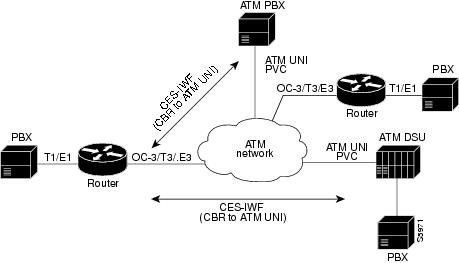
CES-IWF is a service based on ATM Forum standards that allows communications between CBR and ATM UNI interfaces, that is, between non-ATM telephony devices (such as classic PBXs or TDMs) and ATM devices (such as Cisco 7200 series routers). Thus, a Cisco 7200 series router equipped with an ATM CES port adapter offers a migration path from classic T1/E1 CBR data communications services to emulated CES T1/E1 unstructured (clear channel) services or structured (N x 64) services in an ATM network. A Cisco uBR7200 series equipped with an ATM CES port adapter offers an ATM WAN connection between the broadband cable network and the Internet.
Figure 1-1 is a simplified representation of CES-IWF functions in an ATM network.
Figure 1-1 Typical CES-IWF Operations in an ATM Network
The circuit emulation services offered by the ATM CES port adapter are discussed in the following sections:
•![]() T1/E1 Unstructured (Clear Channel) CES Services
T1/E1 Unstructured (Clear Channel) CES Services
•![]() T1/E1 Structured (N x 64) CES Services
T1/E1 Structured (N x 64) CES Services
•![]() Channel-Associated Signaling (for Structured CES Services Only)
Channel-Associated Signaling (for Structured CES Services Only)
T1/E1 Unstructured (Clear Channel) CES Services
Unstructured CES services in an ATM network emulate point-to-point connections over T1/E1 leased lines. This service maps the entire bandwidth necessary for a T1/E1 leased line connection across the ATM network, allowing users to interconnect PBXs, TDMs, and video conferencing equipment. Unstructured CES operations do not decode or alter the CBR data in any way.
The ATM CES port adapter supports DSX-1 physical interfaces, providing T1/E1 unstructured (clear channel) CBR data transmission services to Cisco 7200 series and Cisco uBR7200 series users at a rate of 1.544 Mbps for T1 and 2.048 Mbps for E1.
The use of an ATM CES port adapter for unstructured CES services simulates a point-to-point T1/E1 leased line across your ATM network.
Figure 1-2 is a generalized representation of how T1/E1 unstructured CES services are set up in conjunction with a Cisco 7200 series router equipped with an ATM CES port adapter.
Figure 1-2 T1/E1 Unstructured CES Services Across Leased Lines

Figure 1-3 is a general example of unstructured CES applications in an ATM network. In unstructured CES services, user CBR data received from an edge device at one side of the network is segmented into ATM cells and propagated through the ATM network. After traversing the network, the ATM cells are reassembled into a CBR bit stream that matches the original user data. This CBR data is then passed out of the network to the edge device at the destination endpoint.
Figure 1-3 T1/E1 CES Applications in ATM Network

T1/E1 Structured (N x 64) CES Services
The T1/E1 structured (N x 64) CES services enable a CES module to function like a classic digital access and crossconnect system (DACS) switch.
The ATM CES port adapter supports DSX-1 physical interfaces, providing T1/E1 channelized data transmission services at a rate of 1.544 Mbps for T1 and 2.048 Mbps for E1.
Using an ATM CES port adapter, you can map a single DS0 channel or multiple DS0 channels across an ATM network. Each T1 port has up to 24 time slots, and each E1 port has up to 31 time slots for allocation to structured CES circuits. Each time slot can transmit CBR data at a rate of 64 kbps, or at 56 kbps, if you choose to use optional channel associated signaling (CAS). The "Channel-Associated Signaling (for Structured CES Services Only)" section, describes the CAS mechanism.
Figure 1-4 illustrates the digital crossconnect and channelized mapping functions offered by a Cisco 7200 series router or a Cisco uBR7200 series equipped with an ATM CES port adapter. Single or multiple DS0 time slots can be mapped across the ATM network. Each time slot (or DS0 channel) represents a single N x 64 circuit that can transmit CBR data at a rate of 64 kbps.
Multiple N x 64 circuits can be connected to a single port, if separate time slots are used.
With T1/E1 structured CES services, network designers can simplify networks by eliminating TDM devices, using ATM CES port adapters instead as a means of allocating T1/E1 bandwidth to PBXs and teleconferencing equipment.
Figure 1-4 Digital Access and Crossconnect (DACS) Functions of CES Modules

As Figure 1-4 demonstrates, structured services in an ATM CES port adapter allow T1/E1-formatted CBR data to be provisioned into individual DS0 channels (PVCs) or groups of DS0 channels.
Data from these channels can be sent to multiple individual output ports on a CES module, where the data can be combined with CBR data from other DS0 channels or groups of DS0 channels to form an outgoing T1/E1 bit stream. Thus, you can combine structured CBR data with great flexibility for transport across an ATM network.
Figure 1-5 gives one example of how 24 available N x 64 time slots for T1 (31 time slots for E1 not shown) in an ATM CES port adapter can be combined to accomplish structured CBR data transport in an ATM network. The DS0 channels can be grouped as either contiguous or noncontiguous time slots.
The ingress (source) DS0 channels can be mapped into different DS0 channels on egress from the ATM network at the destination node.
Figure 1-5 Time Slots for Structured Services in PA-A2 ATM CES Port Adapters

For CES structured services, each DS0 time slot represents a data bandwidth of 64 kbps for CBR data transport. If optional channel associated signaling (CAS) is being used, however, a data bandwidth of 56 kbps per DS0 time slot is available for CBR data transport.
Figure 1-5 shows one end of three PVCs that have been provisioned for structured CBR data transport. Think of these DS0 channels as the source ends of the PVCs. The destination ends of the PVCs each require the allocation of an identical number of DS0 time slots.
However, the actual DS0 numbers assigned at the destination node can differ from those assigned at the source node. In other words, the DS0 numbers at each end of the PVC need not correspond one for one. Only the actual numbers of time slots provisioned at each end of the PVC must agree.
For example, the circuit identified as PVC No. 3 in Figure 1-5 requires a similar bundling of three time slots at the destination end of the PVC (representing a data bandwidth of 192 kbps) in order for the circuit to operate properly.
Channel-Associated Signaling (for Structured CES Services Only)
Because the ATM CES port adapter emulates constant bit rate services over ATM networks, it must be capable of providing support for handling channel-associated signaling (CAS) information introduced into structured CES circuits by PBXs and time-division multiplexing (TDM) devices. An optional CAS feature for the ATM CES port adapter meets this requirement.
With respect to the CAS information carried in a CBR bit stream, an ATM CES port adapter can be configured to operate as follows:
•![]() Without the optional CAS feature enabled (the default state).
Without the optional CAS feature enabled (the default state).
In this case, the ATM CES port adapter does not sense the CAS information (carried as so-called "ABCD" bits in the CBR bit stream) and provides no support for CAS functions.
•![]() With the optional CAS feature enabled, but without the optional (Cisco-proprietary) "on-hook detection" feature enabled.
With the optional CAS feature enabled, but without the optional (Cisco-proprietary) "on-hook detection" feature enabled.
In this case, in addition to packaging incoming CBR data into ATM AAL1 cells in the usual manner for transport through the network, the ATM CES port adapter in the ingress node senses the ABCD bit patterns in the incoming data, incorporates these patterns in the ATM cell stream, and propagates the cells to the next node in the network. The ATM cells are transported across the network from link to link until the egress node is reached.
At the egress node, the ATM CES port adapter strips off the ABCD bit patterns carried by the ATM cells, reassembles the CAS ABCD bits and the user's CBR data into the original form, and passes the frames out of the ATM network in the proper DS0 time slot.
All these processes occur transparently without user intervention.
•![]() With both the optional CAS and on-hook detection features enabled.
With both the optional CAS and on-hook detection features enabled.
In this case, the CAS and on-hook detection features work together to enable an ingress node in an ATM network to monitor on-hook and off-hook conditions for a specified 1 x 64 structured CES circuit. As implied by the notation "1 x 64," the on-hook detection (or bandwidth-release) feature is supported only in a structured CES circuit that involves a single DS0 time slot at each end of the connection.
The DS0 time slot configured for the structured CES circuit at the ingress node (time slot 2) can be different from the DS0 time slot configured at the egress node (time slot 4). Only one such time slot can be configured at each end of the circuit when the on-hook detection feature is used.
When you invoke this feature, the ingress ATM CES port adapter monitors the ABCD bits in the incoming CBR bit stream to detect on-hook and off-hook conditions in the circuit. In an "off-hook" condition, all the bandwidth provisioned for the specified CES circuit is used for transporting ATM AAL1 cells across the network from the ingress node to the egress node.
In an on-hook condition, the network periodically sends dummy ATM cells from the ingress node to the egress node to maintain the connection. However, these dummy cells consume only a fraction of the circuit's reserved bandwidth, leaving the remainder of the bandwidth available for use by other network traffic. This bandwidth-release feature enables the network to make more efficient use of its resources.
When the CAS feature is enabled for a CES circuit, the bandwidth of the DS0 channel is limited to 56 kbps for user data, because CAS functions consume 8 kbps of channel bandwidth for transporting the ABCD signaling bits. These signaling bits are passed transparently from the ingress node to the egress node as part of the ATM AAL1 cell stream.
In summary, when the optional CAS and on-hook detection features are enabled, the following conditions apply:
•![]() The permanent virtual connection (PVC) provisioned for the CES circuit always exists.
The permanent virtual connection (PVC) provisioned for the CES circuit always exists.
•![]() The bandwidth for the CES circuit is always reserved.
The bandwidth for the CES circuit is always reserved.
•![]() During an on-hook state, most of the bandwidth reserved for the CES circuit is not in use. (Dummy cells are sent from the ingress node to the egress node to maintain the connection.) Therefore, this bandwidth becomes available for use by other network traffic, such as available bit rate (ABR) traffic.
During an on-hook state, most of the bandwidth reserved for the CES circuit is not in use. (Dummy cells are sent from the ingress node to the egress node to maintain the connection.) Therefore, this bandwidth becomes available for use by other network traffic, such as available bit rate (ABR) traffic.
•![]() During an off-hook state, all the bandwidth reserved for the CES circuit is dedicated to that circuit.
During an off-hook state, all the bandwidth reserved for the CES circuit is dedicated to that circuit.
See "Configuring the PA-A2 ATM CES Port Adapter," for more information on the procedures for enabling the CAS feature and configuring structured CES services.
Network Timing Services for CES Operations
Circuit emulation services internetworking functions (CES-IWF) and constant bit rate (CBR) traffic relate to a quality of service (QoS) classification defined by the ATM Forum for Class A (AAL1) traffic in ATM networks. In general, Class A traffic pertains to voice and video transmissions.
In an ATM networking environment, CBR refers to a particular class of traffic that is generated by edge (source) devices and propagated into ATM networks for transmission to other edge (destination) devices in the network.
The ATM CES port adapter is designed specifically to handle CBR traffic in an ATM networking environment. To provide requisite timing functions in support of CES operations, you can specify any one of three clocking modes covered in the following sections:
•![]() Network Clock Synchronization
Network Clock Synchronization
•![]() Designating a PRS Source Port in a Cisco 7200 Series Router or Cisco uBR7200 series
Designating a PRS Source Port in a Cisco 7200 Series Router or Cisco uBR7200 series
•![]() Network Clock Distribution in a Cisco 7200 Series Router or a Cisco uBR7200 series
Network Clock Distribution in a Cisco 7200 Series Router or a Cisco uBR7200 series
However, to support synchronous clocking or SRTS clocking in your ATM networking environment, your network must incorporate the following facilities:
•![]() A primary reference source (PRS)—Throughout this document, the term PRS refers to a precision reference timing signal that must be made available, wherever required, to synchronize the flow of CBR data from its source to its destination.
A primary reference source (PRS)—Throughout this document, the term PRS refers to a precision reference timing signal that must be made available, wherever required, to synchronize the flow of CBR data from its source to its destination.
•![]() Network clock synchronization services—This refers to a network clock synchronization and distribution service that provides a PRS to those user and network devices that require a precision reference timing signal for synchronizing the flow of CBR traffic.
Network clock synchronization services—This refers to a network clock synchronization and distribution service that provides a PRS to those user and network devices that require a precision reference timing signal for synchronizing the flow of CBR traffic.
Network Clock Synchronization
Any constant bit rate (CBR) edge device that communicates with another CBR edge device across an ATM network must be driven by a clocking signal of identical frequency. This "synchronized" signal controls the rate of CBR data insertion into the network, and also the rate of extraction of CBR data from the network. If the clock frequency is not synchronized at both the ingress and egress nodes of the circuit, the data queues and buffers in the network will either overflow or underflow, resulting in line errors.
Distributing a clocking signal within the network ensures that each CBR device has access to a common reference clocking signal, called Primary Reference Source (PRS), for synchronizing CBR data transport.
Designating a PRS Source Port in a Cisco 7200 Series Router or Cisco uBR7200 series
Any port adapter in a Cisco 7200 series router or a Cisco uBR7200 series that can receive and distribute a network timing signal can propagate that signal to any other port adapter in the chassis that has similar capabilities.
By issuing the network-clock-select command with appropriate parameters, you can define a particular port in a Cisco 7200 series router or a Cisco uBR7200 series to serve as the source of a PRS for the entire chassis or for other devices in the networking environment. This command enables you to designate a particular port in a Cisco 7200 series router or a Cisco uBR7200 series to serve as a "master clock" source in distributing a single clocking signal throughout the chassis or to other network devices. This clocking signal can be distributed wherever needed in the network to globally synchronize the flow of CBR data. The use of this command is described in "Configuring the PA-A2 ATM CES Port Adapter."
Network Clock Distribution in a Cisco 7200 Series Router or a Cisco uBR7200 series
When equipped with an ATM CES port adapter and appropriate software, any Cisco 7200 series router or a Cisco uBR7200 series can serve as a means for receiving and distributing a PRS to other devices in the network.
A Cisco 7200 series router or a Cisco uBR7200 series can make use of a PRS that originates from any one of several sources in the networking environment.
Figure 1-6 shows three possible sources of a PRS when two Cisco 7206 routers are connected back-to-back. However, you should not interpret that to mean that only three such clocking signals can be made available for use in the ATM network. In fact, more than three clocking signals may be present in the Cisco 7200 series router or Cisco uBR7200 series operating environment.
The important concepts that you should take from Figure 1-6 include the following:
•![]() Up to four clocking signals can be defined per Cisco 7200 series router or a Cisco uBR7200 series in the network.
Up to four clocking signals can be defined per Cisco 7200 series router or a Cisco uBR7200 series in the network.
•![]() The PRS that is used in Cisco 7200 series routers or a Cisco uBR7200 series must be traceable to a single clock source. (In Figure 1-6, Router No. 2's PRS is traceable to Router No. 1's PRS.)
The PRS that is used in Cisco 7200 series routers or a Cisco uBR7200 series must be traceable to a single clock source. (In Figure 1-6, Router No. 2's PRS is traceable to Router No. 1's PRS.)
Figure 1-6 Cisco 7206 Routers Connected Back-to-Back

Each PRS depicted in Figure 1-6 is externally generated—that is, the timing signal originates from a source outside the router. Also shown is an OC-3 trunk line that can propagate a PRS between adjacent router/network devices.
If the Router No. 1 priority 1 PRS fails (CBR 4/0), the network clock synchronization service automatically recovers network timing by using the Router No. 1 priority 2 PRS (CBR 4/3).
Assume, for example, that the T1/E1 line (CBR 4/0) at Router No. 1 in Figure 1-6 is currently supplying PRS to the network. If this PRS fails, the T1/E1 line (CBR 4/3) at the same router is used as PRS.
Router No. 2 has ATM 2/0 as its PRS. If the ATM 2/0 port fails, there is no configured alternate clock source for PRS. The default clock source is the local oscillator. But, in this case, this is not a problem because the traffic from the T1/E1 CBR ports is also disrupted. In the Cisco 7200 series router or the Cisco uBR7200 series, all T1/E1 traffic goes only on the ATM WAN uplink. When ATM 3/0 goes up, the PRS is automatically recovered.
If the Router No. 1 priority 1 PRS is restored to service, the network clock synchronization service automatically reverts to this PRS for timing purposes, regardless of which lower priority PRS may be active at the time.
Figure 1-7 illustrates Cisco 7206 routers connected to an ATM network. This figure shows how a PRS can be derived from the ATM network and provided to an edge node and propagated through the network to synchronize the flow of CBR data between the communicating ATM end nodes.
In Figure 1-7, when the PRS clock source is taken from the ATM network, all the transmit nodes at the edge of the network on T1/E1 trunk lines on the ATM CES port adapter in Routers 1, 2, and 3 are synchronized.
Figure 1-7 Cisco 7206 Routers Connected to ATM Network

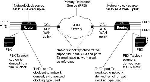
Figure 1-8 illustrates a typical configuration of a network clock source. In this figure, the PBX T1/E1 transmit clocks, ATM CES T1/E1 transmit clocks, ATM CES OC-3/T3/E3 ATM WAN uplinks, and ATM network OC-3/T3/E3 ATM port transmit clocks are all derived from and referenced to a single clock source, the PRS. This limits the jitter and wander in the emulated circuits.
Figure 1-8 Typical Configuration of Network Clock Source
Clocking Modes for CES Operations
For CES operations, three clocking modes can be used in conjunction with any ATM CES port adapter. These clocking modes are described in the following sections in the recommended order of consideration and use:
•![]() Synchronous Residual Time Stamp Clocking Mode
Synchronous Residual Time Stamp Clocking Mode
Synchronous Clocking Mode
Synchronous clocking mode requires a PRS and network clock synchronization services. When equipped with an ATM CES port adapter and appropriate software, any Cisco 7200 series router or Cisco uBR7200 series can serve as a means for synchronizing the flow of user CBR traffic through the network.
Synchronous clocking can be used for unstructured service (clear channel) and is the only clocking mode for structured (N x 64 kbps) CES services. It is the recommended option for three reasons:
•![]() First, this clocking mode is the only one that supports full CES functionality. SRTS and adaptive clocking do not support structured CES services.
First, this clocking mode is the only one that supports full CES functionality. SRTS and adaptive clocking do not support structured CES services.
•![]() Second, synchronous clocking exhibits superior stability, reliability, and wander/jitter characteristics.
Second, synchronous clocking exhibits superior stability, reliability, and wander/jitter characteristics.
•![]() Third, synchronous clocking is typically used in public telephone systems, making a precision reference signal readily and widely available for the synchronizing of CBR data transport.
Third, synchronous clocking is typically used in public telephone systems, making a precision reference signal readily and widely available for the synchronizing of CBR data transport.
For these reasons, synchronous clocking is the default clocking mode for all CES services.
Synchronous Residual Time Stamp Clocking Mode
Synchronous residual time stamp (SRTS) clocking requires a PRS and network clock synchronization services. SRTS, which can be used only for unstructured services, carries asynchronous DS1 circuits. In this case, the input service clock frequency must be recovered at the output CES-IWF. SRTS is one of the clocking modes that can be used for recovering this clock frequency.
The SRTS clocking mode, which requires a network-wide reference clock, measures the service clock input frequency against a network-wide synchronization signal that must be present in the CES-IWF, and sends different signals, called residual time stamps, in the AAL1 header to the reassembly IWF. At the output IWF, the differences can be combined with the network-wide synchronization signal, to re-create the input service clock. The network-wide reference clock is described in the "Network Clock Distribution in a Cisco 7200 Series Router or a Cisco uBR7200 series" section.
Adaptive Clocking Mode
Adaptive clocking mode requires neither a PRS nor network clock synchronization services for effective handling of CBR traffic. However, as is the case with SRTS clocking, adaptive clocking can be used only for unstructured (clear channel) CES services.

Note ![]() Although this clocking mode is the simplest and easiest to implement in an ATM network, it exhibits the poorest wander and jitter performance of all the available clocking modes. Therefore, Cisco does not recommend its use, except in instances where a PRS and network clock synchronization services are not available.
Although this clocking mode is the simplest and easiest to implement in an ATM network, it exhibits the poorest wander and jitter performance of all the available clocking modes. Therefore, Cisco does not recommend its use, except in instances where a PRS and network clock synchronization services are not available.
The term adaptive clocking is used because the rate at which CBR data is propagated through an ATM network is driven by the rate at which such data is introduced into the network by the user's edge equipment.
For example, adaptive clocking in an ATM CES port adapter derives timing for data transport by calculating the "average" rate at which data arrives and conveying that data to the output port of the module at an equivalent rate. For this reason, the actual rate of CBR data flow through the network may vary when adaptive clocking is used, depending on how rapidly CBR data is being introduced into the network.
CBR data transport through the network occurs in a "pseudo synchronous" manner that ensures the integrity of the data.
Rather than using a clocking signal to convey CBR traffic through an ATM network, adaptive clocking obtains appropriate timing for data transport by calculating an average data rate for the CBR traffic.
For example, if CBR data is arriving at an ATM CES port adapter at a rate of so many bits per second, then that rate is used, in effect, to govern the flow of CBR data through the network. Meanwhile, however, the ATM CES port adapter automatically calculates the average data rate by means of microcode (firmware) built into the board. This calculation occurs while user data traverses the network.
When the ATM CES port adapter senses that its segmentation and reassembly (SAR) buffer is filling up, it increases the rate of the transmit (TX) clock for its output port, thereby "draining" the buffer.
Similarly, the ATM CES port adapter slows down the transmit clock of its output port if it senses that the buffer is being "drained" faster than CBR data is being received. In this manner, adaptive clocking attempts to minimize wide variations in SAR buffer loading while providing an effective means of propagating CBR traffic through the network.
Implementing adaptive clocking is simple and straightforward, because it does not require network clock synchronization services, a PRS, or the advance planning typically associated with the development of a logical network timing map. However, adaptive clocking does not support structured CES services, and it exhibits relatively high wander characteristics.
Summary of Clocking Modes
Table 1-1 summarizes the characteristics of the three clocking modes available for handling CBR traffic in an ATM networking environment. Although the wander and jitter characteristics of these clocking modes differ, each mode preserves the integrity of the user's CBR data, ensuring its error-free transport from source to destination.
Other Network Factors Relevant to CES Operations
The following factors affect the functioning of CES circuits:
•![]() The intended source and destination nodes for CES circuits.
The intended source and destination nodes for CES circuits.
•![]() The clocking mode that best suits your particular network topology and timing requirements for the handling of CBR data.
The clocking mode that best suits your particular network topology and timing requirements for the handling of CBR data.
Although synchronous clocking is the recommended (default) clocking mode for CES operations, this fact does not preclude other clocking modes from consideration.
•![]() The cell delay variation (CDV) characteristics of the network, measured in microseconds.
The cell delay variation (CDV) characteristics of the network, measured in microseconds.
•![]() Each end-to-end CES circuit exhibits delay characteristics, based on the following factors:
Each end-to-end CES circuit exhibits delay characteristics, based on the following factors:
–![]() The delay characteristics of the individual devices participating in the CES circuit. Each network device contributes some increment of delay, reflecting that device's unique electrical characteristics.
The delay characteristics of the individual devices participating in the CES circuit. Each network device contributes some increment of delay, reflecting that device's unique electrical characteristics.
–![]() The number of intermediate hops through which the CBR data must pass in traversing the network from source to destination. The network designer/administrator calculates a CDV value for each hop in the data path in order to establish a maximum allowable CDV value for the network at large.
The number of intermediate hops through which the CBR data must pass in traversing the network from source to destination. The network designer/administrator calculates a CDV value for each hop in the data path in order to establish a maximum allowable CDV value for the network at large.
–![]() The type and speed of the trunk lines interconnecting the ATM networks.
The type and speed of the trunk lines interconnecting the ATM networks.
–![]() The volume of traffic being handled by the trunk lines at any given time, that is, the degree to which the network may be experiencing congestion conditions.
The volume of traffic being handled by the trunk lines at any given time, that is, the degree to which the network may be experiencing congestion conditions.
Network designers and administrators calculate a maximum allowable CDV value for the network in order to establish network cell delay tolerance limits. Thus, to some degree, the network's maximum allowable CDV value is a measure of the network's expected performance.
When a CDV threshold for the network is established, appropriate buffer sizing can be derived for the network devices involved in any given CES circuit. This helps to ensure that the network will operate as expected.
In the case of an ATM CES port adapter, for example, the maximum allowable CDV value for the network is used to determine an appropriate size (depth) for the segmentation and reassembly (SAR) buffer built into the board. This sizing of the SAR buffer prevents buffer overflow or underflow conditions. An overflow condition can cause a loss of frames, and an underflow condition can cause frames to be repeated.
The actual CDV value for a circuit varies according to the particular data path used for the circuit. Consequently, the depth of the SAR buffer may increase or decrease in proportion to the CDV value for the CES circuit being set up.
You can issue the show ces circuit interface command in an unstructured (clear channel) circuit to measure the current CDV value. See "Configuring the PA-A2 ATM CES Port Adapter," for more information on verifying a configured hard PVC.
For an unstructured hard PVC, the CDV value for the circuit (including all hops) should not exceed a maximum allowable CDV value. The procedure for setting up a hard PVC is described in
"Configuring the PA-A2 ATM CES Port Adapter."
For an unstructured hard PVC, the network automatically determines the best data path through the network and handles the routing of CBR traffic. The network accomplishes this dynamically by means of the ATM connection admission control (CAC) mechanism. The CAC determines the best path through the network by executing a routing algorithm that consults local routing tables in network devices.
If the requested data path is equal to or less than the maximum allowable CDV value established by the network administrator, the connection request is granted. If the requested CES circuit exceeds the maximum allowable CDV value, the connection request is denied. These connection admission control processes occur "on the fly" as network connection requests are initiated.
For example, when a user requests a connection from source node A at one edge of the network to destination node B at the opposite edge of the network, the CAC mechanism takes into account the CDV value for each hop in the requested connection to determine a suitable path through the network that does not exceed the network's maximum allowable CDV value.
PA-A2 ATM CES Port Adapter Overview
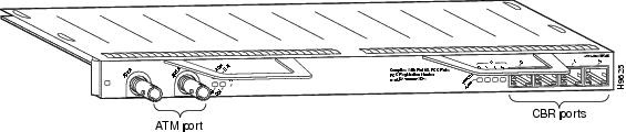
The ATM CES port adapter is a dual-wide module. It has four T1 (1.544 Mbps) or four E1 (2.048 Mbps) 120-ohm constant bit rate (CBR) ports that can support both structured (N x 64 kbps) and unstructured ATM Forum-compliant circuit emulation services (CES), and a single port of an OC-3 (155 Mbps) single-mode intermediate reach or a T3 (45 Mbps) or E3 (34 Mbps) standards-based ATM interface. (See Figure 1-9 and Figure 1-10 for examples of each version.)
The ATM CES port adapter can be used only on a Cisco 7200 series router or a Cisco uBR7200 series that has a 150-MHz network processing engine (NPE-150).
The target application of the ATM CES port adapter is access to a broadband public or private ATM network where multiservice consolidation of voice, video, and data traffic over a single ATM link is a requirement.
Table 1-2 lists the different types of ATM CES port adapters and their associated part numbers.
|
|
|
|---|---|
4 T1 CBR ports and 1 OC-3 ATM SM1 port |
PA-A2-4T1C-OC3SM(=) |
4 T1 CBR ports and 1 T3 ATM port |
PA-A2-4T1C-T3ATM(=) |
4 E1 120-ohm CBR ports and 1 OC-3 ATM SM port |
PA-A2 4E1XC-OC3SM(=) |
4 E1 120-ohm CBR ports and 1 E3 ATM port |
PA-A2-4E1XC-E3ATM(=) |
1 SM = single mode |
Figure 1-9 PA-A2 ATM CES Port Adapter—PA-A2-4T1C-OC3SM(=) or PA-A2 4E1XC-OC3SM(=)

Figure 1-10 PA-A2 ATM CES Port Adapter—PA-A2-4T1C-T3ATM=) or PA-A2 4E1XC-E3ATM(=)
You can install a PA-A2 ATM CES port adapter in any available, horizontally aligned, port of port adapter slots in a Cisco 7200 series router or a Cisco uBR7246.
In previous versions of PPP over ATM, you configure permanent virtual circuits (PVCs) for PPP over ATM on point-to-point subinterfaces. In the current Cisco IOS releases (see the "Minimum Software and Hardware Requirements" section), each PPP over ATM connection no longer requires two Internet Data Blocks (IDBs), one for virtual access interfaces, and one for ATM subinterfaces. Instead, you can configure multiple PVCs for PPP over ATM on multipoint subinterfaces.
The new version of PPP over ATM also complies with the Internet Engineering Task Force (IETF) draft on multiplexed encapsulation. The previous version of PPP over ATM supported Cisco's Frame Forwarding data encapsulation (aal5ciscoppp). In the current Cisco IOS software releases (see the "Minimum Software and Hardware Requirements" section), PPP over ATM is enhanced to support virtual circuit (VC) multiplexed PPP payloads as specified by the PPP over AAL5 Internet Draft (12/23/97). Therefore, the name for this new PPP over ATM feature is more accurately IETF PPP over ATM.
Note ![]() The IETF PPP over ATM feature does not currently support LLC encapsulated PPP over ATM Adaption Layer 5 (AAL5).
The IETF PPP over ATM feature does not currently support LLC encapsulated PPP over ATM Adaption Layer 5 (AAL5).
Features
The PA-A2 ATM CES port adapter has the following features:
•![]() Cross-connect Circuit Emulation Services (CES)—Structured and unstructured
Cross-connect Circuit Emulation Services (CES)—Structured and unstructured
•![]() Four-port T1 or E1 (120-ohm) constant bit rate (CBR) for CES
Four-port T1 or E1 (120-ohm) constant bit rate (CBR) for CES
•![]() Network timing distribution
Network timing distribution
•![]() On/off hook Channel Associated Signaling (CAS)
On/off hook Channel Associated Signaling (CAS)
•![]() Segmentation and reassembly (SAR) of up to 512 buffers simultaneously, where each buffer represents a transmit channel
Segmentation and reassembly (SAR) of up to 512 buffers simultaneously, where each buffer represents a transmit channel
•![]() Up to 2046 virtual circuits (VCs) and 124 CBR VCs
Up to 2046 virtual circuits (VCs) and 124 CBR VCs
•![]() ATM adaptation layer (AAL) 5
ATM adaptation layer (AAL) 5
•![]() Single-port SONET/SDH OC-3 single-mode intermediate reach ATM uplink
Single-port SONET/SDH OC-3 single-mode intermediate reach ATM uplink
•![]() Single-port DS3 ATM WAN uplink over T3/E3
Single-port DS3 ATM WAN uplink over T3/E3
•![]() Traffic shaping (per VP and VC)
Traffic shaping (per VP and VC)
•![]() ABR, CBR, VBR, and UBR Quality of Service (QoS)
ABR, CBR, VBR, and UBR Quality of Service (QoS)
•![]() Operation, Administration, and Maintenance (OAM) cells
Operation, Administration, and Maintenance (OAM) cells
•![]() Online insertion and removal (OIR)
Online insertion and removal (OIR)
In addition, the ATM CES port adapters now support the following additional features:
•![]() New VC configuration
New VC configuration
•![]() VC integrity management
VC integrity management
•![]() PVC discovery
PVC discovery
•![]() Multiprotocol inverse ARP
Multiprotocol inverse ARP
•![]() PPP over ATM
PPP over ATM
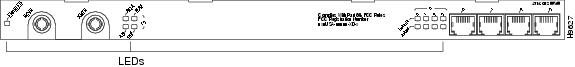
LEDs
The PA-A2 ATM CES port adapter has 13 LEDs that indicate the status of the port adapter, the status of the uplink ports, and the status of the CBR ports. (See Figure 1-11 and Figure 1-12.)
Figure 1-11 LEDs on the PA-A2 ATM CES Port Adapter—OC-3 Single Mode
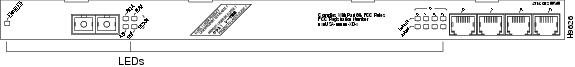
Figure 1-12 LEDs on the PA-A2 ATM CES Port Adapter—T3/E3
After system initialization, the enabled LED goes on to indicate that the PA-A2 ATM CES port adapter has been enabled for operation.
The following conditions must be met before the PA-A2 ATM CES port adapter is enabled:
•![]() The PA-A2 ATM CES port adapter is correctly connected and is receiving power.
The PA-A2 ATM CES port adapter is correctly connected and is receiving power.
•![]() A valid system software image for the PA-A2 ATM CES port adapter has been downloaded successfully.
A valid system software image for the PA-A2 ATM CES port adapter has been downloaded successfully.
•![]() The system recognizes the installed PA-A2 ATM CES port adapter.
The system recognizes the installed PA-A2 ATM CES port adapter.
If any of the above conditions are not met, or if the initialization fails for other reasons, the enabled LED does not go on.
Table 1-3 describes the LED that indicates port adapter status.
|
|
|
|
|
ENABLED |
Green |
On |
PA-A2 ATM CES port adapter is enabled for operation. |
Table 1-4 describes the LEDs that indicated uplink port status.
Table 1-5 describes the LEDs that indicated CBR port status. There are four Enabled and four Alarm LEDs, one for each port.
PA-A2 ATM CES Cables, Connectors, and Pinouts
Cables on the ATM CES port adapter fall into two categories described in the following sections:
ATM CES port adapter interfaces are full-duplex. You must use the appropriate ATM interface cable and CBR cable to connect the ATM CES port adapter with an external ATM network. The ATM CES port adapters, shown in Figure 1-9 and Figure 1-10, provides an interface to ATM switching fabrics for transmitting and receiving data at rates of up to 155 Mbps bidirectionally for OC-3, 44.736 Mbps bidirectionally for DS3 over T3, and 34 Mbps bidirectionally for E3.
ATM Port Cables
Two types of cables are available for use with the ATM CES port adapter's OC-3 and T3/E3 ATM ports:
•![]() An OC-3 single-mode ATM interface cable, which is used to connect a router to an external DSU (an ATM network)
An OC-3 single-mode ATM interface cable, which is used to connect a router to an external DSU (an ATM network)
•![]() A T3/E3 75-ohm coaxial interface cable, which is used to connect a router to an external DSU (an ATM network)
A T3/E3 75-ohm coaxial interface cable, which is used to connect a router to an external DSU (an ATM network)
Both ATM cables conform to the EIA/TIA-612 and EIA/TIA-613 specifications. The ATM port on the ATM CES port adapter is a DTE device.
For OC-3 single-mode, the ATM CES port adapter connects to the SONET/SDH 155-Mbps single-mode optical fiber physical layer, either STS-3C or STM-1. The connection is made by means of single-mode OC-3 ATM cables with SC connectors (see Figure 1-13). The SONET single-mode SC connector is shipped with removable dust covers on each SC connector. Keep covers on any connectors that are not being used.
For SONET/STC-3C single-mode connections, use one duplex SC connector (see Figure 1-13) or two single SC connectors (see Figure 1-14).
Figure 1-13 Duplex SC Connector

Figure 1-14 Simplex SC Connector

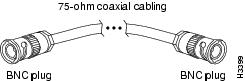
For T3/E3 connections, use a 75-ohm coaxial interface cable (see Figure 1-15). The T3/E3 75-ohm coaxial cable is available from Cisco in five different lengths: 10, 25, 50, 75, and 100 feet. They are not available from outside commercial vendors. The typical maximum distance between stations for T3 transmissions is 450 feet (135 meters) and for E3 transmissions is 1300 feet (390 meters).
Figure 1-15 T3/E3 75-Ohm Coaxial Cable and Connector
Note ![]() For connections in Australia, interconnecting cables shall comply with TS 016, clause 5.5.5.2: "The maximum interconnecting cable insertion loss shall not exceed 12 dB measured at 17,184 kHz. This attenuation should take into account any losses incurred by the presence of a digital distribution frame between equipment."
For connections in Australia, interconnecting cables shall comply with TS 016, clause 5.5.5.2: "The maximum interconnecting cable insertion loss shall not exceed 12 dB measured at 17,184 kHz. This attenuation should take into account any losses incurred by the presence of a digital distribution frame between equipment."
The T3/E3 line interface performs physical layer translation from the ATM CES port adapter to the T3/E3 line interface in accordance with ATM Forum UNI specification Version 3.1, ACCUNET T45 service specifications, and ANSI T1E1.107.
CBR Port Cables
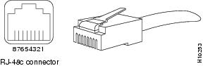
The four CBR interface receptacles on the ATM CES port adapter are RJ-48C for T1 and E1 (120 ohm). Each connection supports T1 or E1 (120-ohm) interfaces that meet T1E1.403 and ACCUNET TR62411 standards. The RJ-48C connection does not require an external transceiver. The CBR ports are T1 interfaces that use UTP, 100-ohm twisted pair cables and E1 interfaces that use UTP, 120-ohm twisted pair cables (see Figure 1-16). The typical maximum distance between stations for T1 and E1 transmissions is 1000 feet (300 meters).
Note ![]() For RJ-48C T1 and E1 (120-ohm) connections in the U.S. and Canada, you can use UTP cables to meet FCC Part 15 Class A EMI requirements. For RJ-48C T1 and E1 (120-ohm) connections in Japan and other countries, you can use STP cables to meet VCCI Class II EMI requirements.
For RJ-48C T1 and E1 (120-ohm) connections in the U.S. and Canada, you can use UTP cables to meet FCC Part 15 Class A EMI requirements. For RJ-48C T1 and E1 (120-ohm) connections in Japan and other countries, you can use STP cables to meet VCCI Class II EMI requirements.
Figure 1-16 CBR 120-Ohm RJ-48C Interface Cable and Connector
ATM Management Information Base Specifications
The ATM UNI specification defines the required management information base (MIB) functionality for ATM interfaces. MIB attributes are readable and writable across the Interim Local Management Interface (ILMI) through use of the Simple Network Management Protocol (SNMP). The ILMI uses SNMP, without UDP, and Internet Protocol (IP) addressing along with the ATM MIB.
The ATM CES port adapter supports RFC 1213, RFC 1406, RFC 1407, and SONET MIB RFC 1595 interface MIBs. Refer to the ATM UNI specification for additional details on the MIBs.
Fibre-Optic Transmission Specifications
The following sections describe the SONET specifications for fiber-optic transmissions, define the power budget, and help you approximate the power margin for single-mode transmissions:
•![]() Maximum Transmission Distances for SONET
Maximum Transmission Distances for SONET
Maximum Transmission Distances for SONET
The SONET specification for fiber-optic transmission defines two types of fiber: single-mode and multimode. Modes can be thought of as bundles of light rays entering the fiber at a particular angle. Single-mode fiber allows only one mode of light to propagate through the fiber, while multimode fiber allows multiple modes of light to propagate through the fiber. Because multiple modes of light propagating through the fiber travel different distances, depending on the entry angles, they arrive at the destination at different times (a phenomenon called modal dispersion). The typical maximum distance between stations, as defined by SONET, for single-mode transmissions is up to 9 miles (15 kilometers). The ATM CES port adapter uses single-mode fiber, which is capable of higher bandwidth and greater cable run distances than multimode fiber.
Use the power budget calculations in the following section to determine actual distances. If the distance between two connected stations is greater than this maximum distance, significant signal loss can result, making transmission unreliable.
Power Budget
To design an efficient optical data link, evaluate the power budget. The power budget is the amount of light available to overcome attenuation in the optical link and to exceed the minimum power that the receiver requires to operate within its specifications. Proper operation of an optical data link depends on modulated light reaching the receiver with enough power to be correctly demodulated.
Attenuation, caused by the passive media components (cables, cable splices, and connectors), is common to single-mode transmission.
The following variables reduce the power of the signal (light) transmitted to the receiver in single-mode transmission:
•![]() Chromatic dispersion (spreading of the signal in time because of the different speeds of light wavelengths)
Chromatic dispersion (spreading of the signal in time because of the different speeds of light wavelengths)
•![]() Modal dispersion (spreading of the signal in time because of the different propagation modes in the fiber)
Modal dispersion (spreading of the signal in time because of the different propagation modes in the fiber)
Attenuation is significantly lower for optical fiber than for other media. For fiber-optic transmission, chromatic and modal dispersion reduce the available power of the system by the combined dispersion penalty (measured in decibels). The power lost over the data link is the sum of the component, dispersion, and modal losses. However, at OC-3 speeds on single-mode fiber, dispersion and modal losses are minimal.
The following sections offer more detail on power budgeting:
•![]() Approximating the ATM CES Port Adapter Power Margin
Approximating the ATM CES Port Adapter Power Margin
•![]() Using Statistics to Estimate the Power Budget
Using Statistics to Estimate the Power Budget
Approximating the ATM CES Port Adapter Power Margin
The single-mode signal source is an injection laser diode. Single-mode transmission is useful for longer distances, because there is a single transmission path within the fiber and smear does not occur. In addition, chromatic dispersion is also reduced because laser light is essentially monochromatic.
The maximum overload specification on the single-mode receiver is -8 dBm. The single-mode receiver can be overloaded when you are using short lengths of fiber, because the transmitter can transmit up to -8 dB, but no damage to the receiver will result from an overload.
Note ![]() If you are connecting to a non-Cisco single-mode SONET receiver or transmitter, insert a 5- to 10-dB attenuator on the link to prevent overloading the receiver that connects short fiber links.
If you are connecting to a non-Cisco single-mode SONET receiver or transmitter, insert a 5- to 10-dB attenuator on the link to prevent overloading the receiver that connects short fiber links.
Higher order mode loss (HOL) results from light from the LED entering the fiber and being radiated into the fiber cladding. A worst case estimate of power margin (PM) for single-mode transmissions assumes minimum transmitter power (PT), maximum link loss (LL), and minimum receiver sensitivity (PR). The worst case analysis provides a margin of error; not all of the parts of an actual system will operate at the worst case levels.
The following equation lists the calculation of the power budget:
PB = PT - PR
The SONET specification requires that the signal meet the worst case parameters listed in Table 1-6.
|
|
|
|---|---|
PT |
-15 dBm |
PR |
-31 dBm |
PB |
-16 dBm |
In the following example of a single-mode power budget, two buildings, 8 kilometers apart, are connected through a patch panel in an intervening building with a total of 12 connectors.
Length of single-mode link = 8 km
12 connectors
The power margin is equal to the PB value minus the link loss:
PM = PB - LL
PM = 16 dB - 8 km (0.5 dB/km) - 12 (0.5 dB)
PM = 16 dB - 4 dB - 6 dB
PM = 6 dB
The value of 6 dB indicates that this link has sufficient power for transmission and does not exceed the maximum receiver input power.
If the power margin is positive, as a rule, the link will work.
Table 1-7 lists the factors that contribute to link loss and the estimate of the link loss value attributable to each factor.
The power margin (calculated above) should be greater than zero. Circuits whose results are less than zero may have insufficient power to operate the receiver.
Using Statistics to Estimate the Power Budget
Statistical models more accurately determine the power budget than the worst case method. Determining the link loss with statistical methods requires accurate knowledge of variations in the data link components. Statistical power budget analysis is beyond the scope of this document. For further information, refer to UNI Forum specifications, ITU-T standards, and your equipment specifications.
For Further Reference
The following publications contain information on determining attenuation and power budget:
•![]() T1E1.2/92-020R2 ANSI, the Draft American National Standard for Telecommunications entitled Broadband ISDN Customer Installation Interfaces: Physical Layer Specification
T1E1.2/92-020R2 ANSI, the Draft American National Standard for Telecommunications entitled Broadband ISDN Customer Installation Interfaces: Physical Layer Specification
•![]() Power Margin Analysis, AT&T Technical Note, TN89-004LWP, May 1989
Power Margin Analysis, AT&T Technical Note, TN89-004LWP, May 1989
Setting ATM CES Port Adapter Jumpers
Depending on the circumstances, you might need to change the configuration of the ATM CES port adapter's receive interface from ungrounded to grounded. (The ATM CES port adapter is configured in manufacturing for ungrounded at the receive interface.) The following steps explain how to set the configuration for grounded or ungrounded:
Step 1 ![]() Attach an ESD-preventive wrist strap to yourself and to an unfinished chassis surface.
Attach an ESD-preventive wrist strap to yourself and to an unfinished chassis surface.
Step 2 ![]() Remove the PA-A2 ATM CES port adapter from the chassis. To do so, follow the steps in the "Port Adapter Removal and Installation" section.
Remove the PA-A2 ATM CES port adapter from the chassis. To do so, follow the steps in the "Port Adapter Removal and Installation" section.
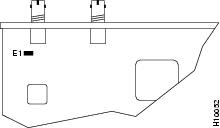
Step 3 ![]() With the PA-A2 ATM CES port adapter on an antistatic mat, use a number 1 Phillips screwdriver to remove the three screws that secure the plastic shield to the ATM CES port adapter's printed circuit board. (See Figure 1-17.) Save the screws.
With the PA-A2 ATM CES port adapter on an antistatic mat, use a number 1 Phillips screwdriver to remove the three screws that secure the plastic shield to the ATM CES port adapter's printed circuit board. (See Figure 1-17.) Save the screws.
Step 4 ![]() Set the jumper on the PA-A2 ATM CES port adapter to grounded (covered pins) or ungrounded (uncovered pins). This jumper is at location E1 on the port adapter's circuit board. See Figure 1-18.
Set the jumper on the PA-A2 ATM CES port adapter to grounded (covered pins) or ungrounded (uncovered pins). This jumper is at location E1 on the port adapter's circuit board. See Figure 1-18.
Note ![]() The PA-A2 ATM CES port adapter is configured in manufacturing for ungrounded (uncovered pins) at the receive interface.
The PA-A2 ATM CES port adapter is configured in manufacturing for ungrounded (uncovered pins) at the receive interface.
Step 5 ![]() Replace the plastic shield over the PA-A2 ATM CES port adapter's jumper and secure the shield to the port adapter's printed circuit board using a number 1 Phillips screwdriver and the three screws that you saved.
Replace the plastic shield over the PA-A2 ATM CES port adapter's jumper and secure the shield to the port adapter's printed circuit board using a number 1 Phillips screwdriver and the three screws that you saved.
Step 6 ![]() Replace the PA-A2 ATM CES port adapter in the chassis. To do so, follow the instructions in the "Port Adapter Removal and Installation" section.
Replace the PA-A2 ATM CES port adapter in the chassis. To do so, follow the instructions in the "Port Adapter Removal and Installation" section.
Figure 1-17 Removing the Plastic Shield
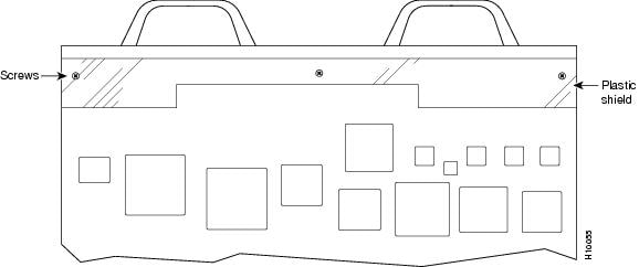
Figure 1-18 Location of Jumper on PA-A2-4E1XC-E3ATM
PA-A2 ATM CES Port Adapter Slot Locations on the Supported Platforms
This section discusses the module slot locations on the supported platforms. The illustrations that follow summarize slot location conventions on each platform:
•![]() Cisco 7200 Series Routers and Cisco uBR7200 Series Routers Slot Numbering
Cisco 7200 Series Routers and Cisco uBR7200 Series Routers Slot Numbering
Cisco 7200 Series Routers and Cisco uBR7200 Series Routers Slot Numbering
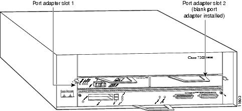
Slots in the Cisco 7202 router are numbered from left to right, slot 1 and slot 2. (See Figure 1-19.)
Figure 1-19 Module Slots in the Cisco 7202
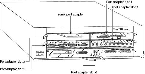
Slots in the Cisco 7204 router are numbered from left to right, beginning with slot 1 and continuing through slot 4. Slot 0 is the Fast Ethernet port on the I/O controller. (See Figure 1-20.)
Figure 1-20 Module Slots in the Cisco 7204
Slots in the Cisco 7206 are numbered from 1 through 6; slot 0 is reserved for the optional Fast Ethernet port on the I/O controller—if present. (See Figure 1-21.)
Figure 1-21 Module Slots in the Cisco 7206
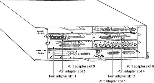
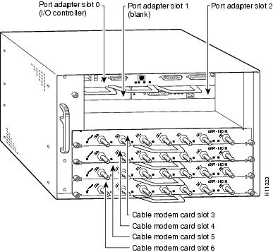
Figure 1-22 shows the slot numbering of modules installed on a Cisco uBR7246 router. The slots are numbered slot 1 and slot 2 for the Cisco uBR7246 and slot 1 for the Cisco uBR7223. (Slot 0 is always reserved for the Fast Ethernet port on the I/O controller—if present.)
Figure 1-22 Module Slots in the Cisco uBR7246
Identifying Interface Addresses
This section describes how to identify the interface addresses for modules in supported platforms. Interface addresses specify the actual physical location of each interface on a router or switch.
Interfaces on the module installed in a router maintain the same address regardless of whether other modules are installed or removed. However, when you move a module to a different slot, the first number in the interface address changes to reflect the new module slot number.
Note ![]() Interface ports are numbered from left to right starting with 0.
Interface ports are numbered from left to right starting with 0.
The following subsections describe the interface address formats for specific platforms:
•![]() Interface Addresses of Cisco 7200 Series Routers and Cisco uBR7200 Series Routers
Interface Addresses of Cisco 7200 Series Routers and Cisco uBR7200 Series Routers
Interface Addresses of Cisco 7200 Series Routers and Cisco uBR7200 Series Routers
The interface address for a module installed in Cisco 7200 series routers or uBR7200 series routers is composed of a two-part number in the format slot/port-number.
In Cisco 7200 series routers, slots are numbered from the lower left to the upper right, beginning with slot 1 and continuing through slot 2 for the Cisco 7202, slot 4 for the Cisco 7204, and slot 6 for the Cisco 7206. (Slot 0 is reserved for the optional Fast Ethernet port on the I/O controller—if present.)
The interface addresses of a 4-port module installed in slot 1 would be 1/0 through 1/4 (slot 1 and interface port 0 through port 4). If the 4-port module was installed in slot 4, these same interfaces would be numbered 4/0 through 4/4 (slot 4 and interface port 0 through port 4).
In Cisco uBR7200 series routers, slots are numbered slot 1 and slot 2 for the Cisco uBR7246. (Slot 0 is always reserved for the Fast Ethernet port on the I/O controller—if present.) The individual interfaces always begin with 0. The number of additional interfaces depends on the number of interface ports on a module.
The interface addresses of a module installed in slot 2 would be 2/0 and 2/1 (slot 2 and interface ports 0 and 1). If a module is installed in slot 1, these same interface addresses would be 1/0 and 1/1 (slot 1 and interface ports 0 and 1).
 Feedback