- Title and copyright: PA-A1 ATM Port Adapter Installation and Configuration
- Preface: PA-A1 ATM Port Adapter Installation and Configuration
- Overview: PA-A1 ATM Port Adapter
- Preparing to Install the PA-A1 ATM Port Adapter
- Removing and Installing the PA-A1 ATM Port Adapter
- Attaching the PA-A1 ATM Interface Cables
- Configuring the PA-A1 ATM Port Adapter
Overview
This chapter describes the PA-A1 ATM port adapter and contains the following sections:
•![]() Asynchronous Transfer Mode Overview
Asynchronous Transfer Mode Overview
•![]() LEDs
LEDs
•![]() Port Adapter Slot Locations on the Supported Platforms
Port Adapter Slot Locations on the Supported Platforms
•![]() Identifying Interface Addresses
Identifying Interface Addresses
Port Adapter Overview
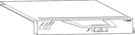
The PA-A1 ATM (see Figure 1-1 and Figure 1-2) is an ATM (OC-3 rate) protocol control information (PCI)-based, multimode or single-mode, intermediate reach, single-width port adapter. The PA-A1 ATM provides a single ATM network interface for the supported platforms.
Figure 1-1 PA-A1 ATM—Faceplate View (PA-A1-OC3SMI Shown)
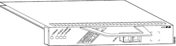
Figure 1-2 PA-A1 ATM—Faceplate View (Multimode PA-A1-OC3MM Shown)
There are no restrictions on slot locations or sequence; you can install a PA-A1 ATM in any available port adapter slot.

Note ![]() Traffic from multiple ATM network interfaces might exceed the bandwidth of the CyBus (VIP2 and VIP4 only), causing packets to be dropped. Although up to five ATM port adapters can be used in a Cisco 7000 series and Cisco 7500 series router (a Cisco 7513 can have up to 11 VIP2s or VIP4s), two ATM port adapter modules per a Cisco 7000 series router or a Cisco 7500 series router is considered to be a practical limit.
Traffic from multiple ATM network interfaces might exceed the bandwidth of the CyBus (VIP2 and VIP4 only), causing packets to be dropped. Although up to five ATM port adapters can be used in a Cisco 7000 series and Cisco 7500 series router (a Cisco 7513 can have up to 11 VIP2s or VIP4s), two ATM port adapter modules per a Cisco 7000 series router or a Cisco 7500 series router is considered to be a practical limit.
Asynchronous Transfer Mode Overview
Asynchronous Transfer Mode (ATM) uses cell-switching and multiplexing technology that combines the benefits of circuit switching (constant transmission delay and guaranteed capacity) with those of packet switching (flexibility and efficiency for intermittent traffic).
ATM is a connection-oriented environment. All traffic to or from an ATM network is prefaced with a virtual path identifier (VPI) and virtual channel identifier (VCI). A VPI/VCI pair is considered a single virtual circuit (VC). Each VC is a private connection to another node on the ATM network. It is treated as a point-to-point mechanism to another router or host and is capable of supporting bidirectional traffic.
Each ATM node is required to establish a separate connection to every other node in the ATM network with which it must communicate. All such connections are established using a permanent virtual circuit (PVC) or a switched virtual circuit (SVC) with an ATM signaling mechanism. This signaling is based on the ATM Forum User-Network Interface (UNI) Specification V3.0.
Each VC is considered a complete and separate link to a destination node. Users can encapsulate data across the connection as they see fit. The ATM network disregards the contents of the data. The only requirement is that data be sent to the PA-A1 ATM card in the specific ATM adaptation layer (AAL) format.
An AAL defines the conversion of user information into cells. The AAL segments upper-layer information into cells at the transmitter and reassembles them at the receiver. ATM adaption layer 5 (AAL5), one of four AALs recommended by the International Telecommunication Union Telecommunication Standardization Sector, supports data communications.
An ATM connection transfers raw bits of information to a destination router or host. The ATM router takes the common part convergence sublayer (CPCS) frame, carves it up into 53-byte cells, and sends these cells to the destination router or host for reassembly. 48 bytes of each cell are used for the CPCS data; the remaining 5 bytes are used for cell routing. The 5-byte cell header contains the destination VPI/VCI, payload type, cell loss priority (CLP), and header error control.
Unlike a LAN, which is connectionless, ATM requires certain features to provide a LAN environment to the users. One such feature is broadcast capability. Protocols wanting to broadcast packets to all stations in a subnet must be allowed to do so with a single call to Layer 2. In order to support broadcasting, the router allows you to specify a particular VC as a broadcast VC. When the protocol passes a packet with a broadcast address to the ATM driver, the packet is duplicated and sent to each VC marked as a broadcast VC. This method is known as pseudobroadcasting.
Features
The PA-A1 ATM supports the following features:
•![]() Segmentation and reassembly (SAR) of up to 512 buffers simultaneously, where each buffer represents a packet
Segmentation and reassembly (SAR) of up to 512 buffers simultaneously, where each buffer represents a packet
•![]() Up to 256 transmit buffers for simultaneous fragmentation
Up to 256 transmit buffers for simultaneous fragmentation
•![]() Up to 2048 SAR virtual circuits (VCs)
Up to 2048 SAR virtual circuits (VCs)
•![]() ATM adaptation layer (AAL) 5
ATM adaptation layer (AAL) 5
•![]() Two physical layers: SONET/SDH OC-3 multimode and SONET/SDH OC-3 single-mode intermediate reach
Two physical layers: SONET/SDH OC-3 multimode and SONET/SDH OC-3 single-mode intermediate reach
•![]() Operation, administration, and maintenance (OAM) cells
Operation, administration, and maintenance (OAM) cells
•![]() Online insertion and removal (OIR)
Online insertion and removal (OIR)
The PA-A1 ATM supports the following dynamic random-access memory (DRAM) and synchronous random-access memory (SRAM) configurations that are in the current VIP2 and VIP4 products:
•![]() VIP2-40(=)—2 MB of SRAM and 32 MB of DRAM
VIP2-40(=)—2 MB of SRAM and 32 MB of DRAM
•![]() VIP2-50(=)—4 to 8 MB of SRAM and 32 to 128 MB of DRAM
VIP2-50(=)—4 to 8 MB of SRAM and 32 to 128 MB of DRAM
The PA-A1 ATM supports the following DRAM and SRAM configurations that are in the current Catalyst RSM/VIP2 products:
•![]() VIP2-15(=)—1 MB of SRAM and 16 MB of DRAM
VIP2-15(=)—1 MB of SRAM and 16 MB of DRAM
•![]() VIP2-40(=)—2 MB of SRAM and 32 MB of DRAM
VIP2-40(=)—2 MB of SRAM and 32 MB of DRAM
Note ![]() You can have only one PA-A1 ATM per VIP2 or VIP4, and Catalyst RSM/VIP2. No other port adapter can reside in the other port adapter slot on the VIP2, VIP4, or Catalyst RSM/VIP2. (This restriction is subject to change without notice.)
You can have only one PA-A1 ATM per VIP2 or VIP4, and Catalyst RSM/VIP2. No other port adapter can reside in the other port adapter slot on the VIP2, VIP4, or Catalyst RSM/VIP2. (This restriction is subject to change without notice.)
LEDs
The PA-A1 ATM (both single-mode and multimode) has one row of three status LEDs and one enabled LED. (See Figure 1-3.) The green- and amber-colored LED for each port indicates port status.
Figure 1-3 LEDs on the PA-A1 ATM—Partial Front Panel View
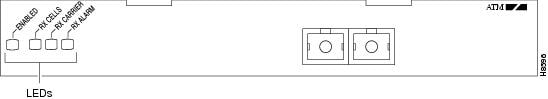
After system initialization, the enabled LED goes on to indicate that the port adapter has been enabled for operation.
The following conditions must be met before the PA-A1 ATM is enabled:
•![]() The PA-A1 ATM is correctly connected and is receiving power.
The PA-A1 ATM is correctly connected and is receiving power.
•![]() A valid system software image for the port adapter has been downloaded successfully.
A valid system software image for the port adapter has been downloaded successfully.
•![]() The system recognizes the PA-A1 ATM, a Catalyst RSM/VIP2 with a PA-A1-ATM, or a VIP2 or a VIP4 with a PA-A1 ATM.
The system recognizes the PA-A1 ATM, a Catalyst RSM/VIP2 with a PA-A1-ATM, or a VIP2 or a VIP4 with a PA-A1 ATM.
If any of the above conditions are not met, or if the initialization fails for other reasons, the enabled LED does not go on.
Table 1-1 lists LED colors and indications.
|
|
|
|
|
|---|---|---|---|
ENABLED |
Green |
On |
Port adapter is enabled for operation. |
RX CELLS |
Green |
On1 |
Port adapter has received an ATM cell. |
RX CARRIER |
Green |
On |
Port adapter has detected a carrier on the receiver cable.2 |
RX ALARM |
Green |
On |
Router has detected an alarm condition. |
1 This LED flickers in normal operation, indicating traffic. 2 For a fiber-optic interface, this means that light is detected. |
Cables and Connectors
ATM port adapter interfaces are full-duplex. You must use the appropriate ATM interface cable to connect the PA-A1 ATM with an external ATM network. The PA-A1 ATM, shown in Figure 1-1 and Figure 1-2, provides an interface to ATM switching fabrics for transmitting and receiving data at rates of up to 155 Mbps bidirectionally. The PA-A1 ATM connects to the SONET/SDH 155 Mbps multimode or single-mode optical fiber—STS-3 or STM-1 physical layer.
An OC-3 ATM interface cable, which is used to connect your router to an external DSU (an ATM network), is available for use with the PA-A1 ATM.
Note ![]() The ATM port on the PA-A1 ATM is considered to be a DTE device.
The ATM port on the PA-A1 ATM is considered to be a DTE device.
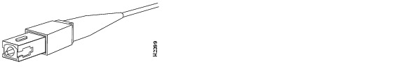
For SONET/SDH multimode and SONET/STC-3 single-mode connections, use one duplex SC connector (see Figure 1-4) or two single SC connectors (see Figure 1-5). The SONET simplex and duplex SC connectors are shipped with removable dust covers on each connector.
Figure 1-4 Duplex SC Connector
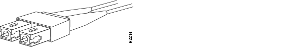
Figure 1-5 Simplex SC Connector
Single-mode and multimode cables should perform to the following specifications:
|
|
|
|
|---|---|---|
ISO/IEC 9314-3 |
2 km (all cables in a connection, end-to-end) |
62.5-micron core with an optical loss of 0 to 9 dB, or 50-micron core with an optical loss of 7 dB |
Note ![]() A single fiber link should not mix 62.5- and 50-micron core cable.
A single fiber link should not mix 62.5- and 50-micron core cable.
Management Information Base
The ATM UNI specification defines the required Management Information Base (MIB) functionality for ATM interfaces. MIB attributes are readable and writable across the Interim Local Management Interface (ILMI) using a Simple Network Management Protocol (SNMP). The ILMI uses SNMP, without User Datagram Protocol (UDP), and IP addressing along with the ATM MIB.
The PA-A1 ATM supports RFC 1213 interface MIBs as specified in the ATM MIB V2 specification. Refer to the ATM UNI specification for additional details on the MIB.
Port Adapter Slot Locations on the Supported Platforms
This section discusses port adapter slot locations on the supported platforms. The illustrations that follow summarize slot location conventions on each platform.
Catalyst RSM/VIP2 Slot Numbering
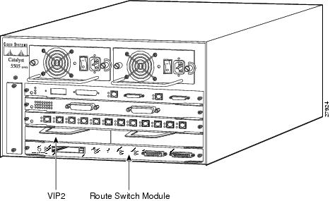
The Catalyst RSM/VIP2 can be installed in any slot except the top slots, which contain the supervisor engine modules. The Catalyst RSM/VIP2 in a Catalyst 5000 family switch does not use interface processor slot numbering; therefore, slots are not numbered in Figure 1-6.
Note ![]() You can have only one ATM port adapter per Catalyst RSM/VIP2 on a Catalyst 5000 family switch. No other port adapter can reside in the other port adapter slot on the Catalyst RSM/VIP2.
You can have only one ATM port adapter per Catalyst RSM/VIP2 on a Catalyst 5000 family switch. No other port adapter can reside in the other port adapter slot on the Catalyst RSM/VIP2.
Note ![]() The Catalyst 5500 switch has 13 slots. Slot 1 is reserved for the supervisor engine module. If a redundant supervisor engine module is used, it would go in slot 2; otherwise, slot 2 can be used for other modules. Slot 13 is a dedicated slot, reserved for the ATM Switch Processor (ASP) module. Refer to the Catalyst 5000 Series Route Switch Module Installation and Configuration Note for any additional slot restrictions for the Catalyst RSM/VIP2.
The Catalyst 5500 switch has 13 slots. Slot 1 is reserved for the supervisor engine module. If a redundant supervisor engine module is used, it would go in slot 2; otherwise, slot 2 can be used for other modules. Slot 13 is a dedicated slot, reserved for the ATM Switch Processor (ASP) module. Refer to the Catalyst 5000 Series Route Switch Module Installation and Configuration Note for any additional slot restrictions for the Catalyst RSM/VIP2.
Figure 1-6 Catalyst 5000 Family Switch with Blank Port Adapters Installed on Catalyst RSM/VIP2
Cisco 7100 Series Routers Slot Numbering
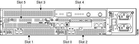
The PA-A1 ATM can be installed in port adapter slot 3 in Cisco 7120 series routers, and in port adapter slot 4 in Cisco 7140 series routers. Figure 1-7 shows a Cisco 7120 with a port adapter installed in slot 3. Figure 1-8 shows a Cisco 7140 with a port adapter installed in slot 4.
Figure 1-7 Port Adapter Slots in the Cisco 7100 Series Router—Cisco 7120 Series
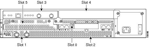
Figure 1-8 Port Adapter Slots in the Cisco 7100 Series Router—Cisco 7140 Series
Cisco 7200 Series and Cisco uBR7200 Series Routers Slot Numbering
Figure 1-9 shows a Cisco 7206 with port adapters installed. In the Cisco 7206 (including the Cisco 7206 and 7206VXR as router shelves in a Cisco AS5800 Universal Access Server), port adapter slot 1 is in the lower left position, and port adapter slot 6 is in the upper right position. (The Cisco 7202 and Cisco 7204 are not shown; however, the PA-A1 ATM can be installed in any available port adapter slot.)
Figure 1-9 Port Adapter Slots in the Cisco 7206
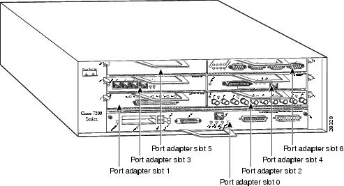
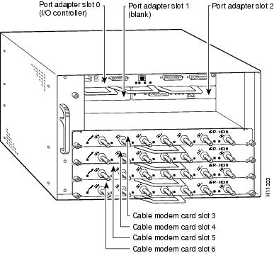
Figure 1-10 shows the slot numbering of port adapters in the Cisco uBR7246 and Cisco uBR7246VXR routers. The port adapter slots are numbered slot 1 and slot 2 for the Cisco uBR7246 and Cisco uBR7246VXR routers and slot 1 for the Cisco uBR7223. (Slot 0 is always reserved for the Fast Ethernet port on the I/O controller—if present.)
Figure 1-10 Port Adapter Slots in the Cisco uBR7246
VIP2 and VIP4 Slot Numbering
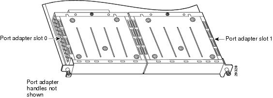
Figure 1-11 shows a VIP motherboard with installed port adapters. With the motherboard oriented as shown in Figure 1-11, the left port adapter is in port adapter slot 0, and the right port adapter is in port adapter slot 1. The slot numbering is the same for the Catalyst RSM/VIP2. The slots are always numbered 0 and 1.
Figure 1-11 VIP Motherboard with Two Port Adapters Installed—Horizontal Orientation Shown
Note ![]() In the Cisco 7000, Cisco 7507, and Cisco 7513 chassis, the VIP motherboard is installed vertically. In the Cisco 7010 and Cisco 7505 chassis, the VIP motherboard is installed horizontally.
In the Cisco 7000, Cisco 7507, and Cisco 7513 chassis, the VIP motherboard is installed vertically. In the Cisco 7010 and Cisco 7505 chassis, the VIP motherboard is installed horizontally.
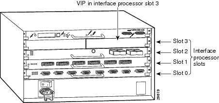
Interface processor slots are numbered as show in Figure 1-12.
Figure 1-12 Interface Slot Numbers—Cisco 7505 shown
Identifying Interface Addresses
This section describes how to identify interface addresses for the PA-A1 ATM in supported platforms. Interface addresses specify the actual physical location of each interface on a router or switch.
Interfaces on the PA-A1 ATM installed in a router maintain the same address regardless of whether other port adapters are installed or removed. However, when you move a port adapter to a different slot, the first number in the interface address changes to reflect the new port adapter slot number.
Interfaces on a PA-A1 ATM installed in a VIP2 or a VIP4 maintain the same address regardless of whether other interface processor slot number changes to reflect the new interface processor slot.
Note ![]() Interface ports are numbered from left to right starting with 0.
Interface ports are numbered from left to right starting with 0.
Table 1-2 explains how to identify interface addresses.
|
|
|
|
|
|---|---|---|---|
Catalyst RSM/VIP2 in Catalyst 5000 family switches |
Port-adapter-slot-number/interface-port-number |
Port adapter slot: 0 or 1 |
0/0 |
Cisco 7120 series routers |
Port-adapter-slot-number/interface-port-number |
Port adapter slot: Always 3 Interface port: Always 0 |
3/0 |
Cisco 7140 series routers |
Port-adapter-slot-number/interface-port-number |
Port adapter slot: Always 4 Interface port: Always 0 |
4/0 |
Cisco 7200 series routers |
Port-adapter-slot-number/interface-port-number |
Port adapter slot: 1 through 6 Interface port: Always 0 |
3/0 |
Cisco uBR7223 router |
Port-adapter-slot-number/interface-port-number |
Port adapter slot: Always 1 Interface port: Always 0 |
1/0 |
Cisco uBR7246 router |
Port-adapter-slot-number/interface-port-number |
Port adapter slot: 1 or 21 Interface port: Always 0 |
2/0 |
VIP2 or VIP4 in Cisco 7000 series or Cisco 7500 series routers |
Interface-processor-slot-number/port-adapter- slot-number/ interface-port-number |
Interface processor slot: 0 through 12 (depends on the number of slots on the router) Port adapter slot: Always 0 or 1 Interface port: Always 0 |
3/0/0 |
1 Port adapter slot 0 is reserved for the Fast Ethernet port on the I/O controller (if present). |
Catalyst RSM/VIP2 Interface Addresses
This section describes how to identify the interface addresses used for the PA-A1 ATM on the Catalyst RSM/VIP2 in Catalyst 5000 family switches. The interface address is composed of a two-part number in the format port-adapter-slot-number/interface-port-number.
See Table 1-2 for the interface address format.
Cisco 7100 Series Routers Interface Addresses
This section describes how to identify the interface addresses used for the PA-A1 ATM in Cisco 7100 series routers. The interface address is composed of a two-part number in the format port-adapter-slot-number/interface-port-number. See Table 1-2 for the interface address format.
Cisco 7200 Series and Cisco uBR7200 Series Routers Interface Addresses
This section describes how to identify the interface addresses used for the PA-A1 ATM in Cisco 7200 series routers or Cisco uBR7200 series routers. The interface address is composed of a two-part number in the format port-adapter-slot-number/interface-port-number. See Table 1-2 for the interface address format.
In Cisco 7200 series routers, port adapter slots are numbered from the lower left to the upper right, beginning with port adapter slot 1 and continuing through slot 2 for the Cisco 7202, slot 4 for the Cisco 7204 and Cisco 7204VXR, and slot 6 for the Cisco 7206 and Cisco 7206VXR. (Port adapter slot 0 is reserved for the optional Fast Ethernet port on the I/O controller—if present.)
The interface address of the interface on the PA-A1 ATM in port adapter slot 1 is 1/0 (port adapter slot 1 and interface 0). If the PA-A1 ATM was in port adapter slot 3, this same interface would be numbered 3/0 (port adapter slot 3 and interface 0.)
In Cisco uBR7200 series routers, the port adapter slots are numbered slot 1 and slot 2 for the Cisco uBR7246 and slot 1 for the Cisco uBR7223 (slot 0 is always reserved for the Fast Ethernet port on the I/O controller—if present). The individual interface port numbers always begin with 0. The number of additional ports depends on the number of ports on a port adapter.
The interface address of the interface on a PA-A1 ATM in port adapter slot 2 is 2/0 (port adapter slot 2 and interface 0). If the PA-A1 ATM was in port adapter slot 1, these same interface would be numbered 1/0 (port adapter slot 1 and interface 0).
VIP2 and VIP4 Interface Addresses
This section describes how to identify the interface addresses used by the PA-A1 ATM on a VIP2 or on a VIP4 in Cisco 7000 series and Cisco 7500 series routers.
Note ![]() Although the processor slots in the seven-slot Cisco 7000 and Cisco 7507 and thirteen-slot Cisco 7513 are vertically oriented and the slots in the five-slot Cisco 7010 and Cisco 7505 are horizontally oriented, all Cisco 7000 series and Cisco 7500 series routers use the same method for slot and port numbering.
Although the processor slots in the seven-slot Cisco 7000 and Cisco 7507 and thirteen-slot Cisco 7513 are vertically oriented and the slots in the five-slot Cisco 7010 and Cisco 7505 are horizontally oriented, all Cisco 7000 series and Cisco 7500 series routers use the same method for slot and port numbering.
See Table 1-2 for the interface address format. The interface address is composed of a three-part number in the format interface-processor-slot-number/port-adapter-slot-number/interface-port-number.
If the VIP2 or VIP4 is inserted in interface processor slot 3, then the interface address of the PA-A1 ATM is 3/1/0 (interface processor slot 3, port adapter slot 1, and interface 0). If the port adapter was in port adapter slot 0 on the VIP2 or VIP4, this same interface address would be 3/0/0.
Note ![]() If you remove the VIP2 or the VIP4 with the PA-A1 ATM from interface processor slot 3 and install it in interface processor slot 2, the interface address becomes 2/1/0.
If you remove the VIP2 or the VIP4 with the PA-A1 ATM from interface processor slot 3 and install it in interface processor slot 2, the interface address becomes 2/1/0.
 Feedback