- Title and copyright: Inverse Multiplexing over ATM Port Adapter Installation and Configuration
- Preface: Inverse Multiplexing over ATM Port Adapter Installation and Configuration
- Overview: Inverse Multiplexing over ATM Port Adapter Installation and Configuration
- Preparing to Install the PA-A3 IMA Port Adapter
- Removing and Installing the PA-A3 IMA Port Adapter
- Configuring the PA-A3 IMA Port Adapter
- Port Adapter Overview
- Inverse Multiplexing over ATM Overview
- Features
- LEDs
- Cables, Connectors, and Pinouts
- Port Adapter Slot Locations on the Supported Platforms
- Cisco 7100 Series Routers Slot Numbering
- Cisco 7200 Series Routers and Cisco 7200 VXR Routers Slot Numbering
- Cisco 7201 Router Slot Numbering
- Cisco 7301 Router Slot Numbering
- Cisco 7304 PCI Port Adapter Carrier Card Slot Numbering
- Cisco 7401ASR Router Slot Numbering
- Cisco 7500 Series Routers VIP Slot Numbering
- Catalyst 6000 Family Switches and Cisco 7600 Series Routers with FlexWAN Module Slot Numbering
- Identifying Interface Addresses
- Cisco 7100 Series Routers Interface Addresses
- Cisco 7200 Series Routers and Cisco 7200VXR Series Routers Interface Addresses
- Cisco 7201 Router Interface Addresses
- Cisco 7301 Router Interface Addresses
- Cisco 7304 PCI Port Adapter Carrier Card Interface Addresses
- Cisco 7401ASR Router Interface Addresses
- Cisco 7500 Series Routers VIP Interface Addresses
- Catalyst 6000 Family Switches and Cisco 7600 Series Routers with FlexWAN Module Interface Addresses
Overview
This chapter describes the PA-A3-IMA port adapter and contains the following sections:
•![]() Inverse Multiplexing over ATM Overview
Inverse Multiplexing over ATM Overview
•![]() LEDs
LEDs
•![]() Cables, Connectors, and Pinouts
Cables, Connectors, and Pinouts
•![]() Port Adapter Slot Locations on the Supported Platforms
Port Adapter Slot Locations on the Supported Platforms
•![]() Identifying Interface Addresses
Identifying Interface Addresses
Port Adapter Overview
The PA-A3-IMA (see Figure 1-1 and Figure 1-2) is a single-width port adapter that allows the Cisco 7100 series routers, Cisco 7200 series routers, Cisco 7200 VXR routers, Cisco 7201 router, Cisco 7301 router, Cisco 7304 PCI Port Adapter Carrier Card in the Cisco 7304 router, Cisco 7401ASR routes, Cisco 7500 series routers, and Catalyst 6000 family switches and Cisco 7600 series routers with a FlexWAN module to support inverse multiplexing over ATM. The PA-A3-IMA supports data rates between DS1 and DS3 levels, or E1 and E3 levels, by combining the bandwidth of multiple DS1 or E1 links into groups that collectively provide higher intermediate rates. This Peripheral Component Interconnect (PCI)-based port adapter is available in a T1 version (PA-A3-8T1 IMA) and an E1 version (PA-A3-8E1 IMA).

Note ![]() PA-A3-8E1 IMA is not supported on Cisco 7401ASR routers.
PA-A3-8E1 IMA is not supported on Cisco 7401ASR routers.
Note ![]() To allow a full view of the port adapter faceplate detail, port adapter handles are not shown in Figure 1-1 and Figure 1-2.
To allow a full view of the port adapter faceplate detail, port adapter handles are not shown in Figure 1-1 and Figure 1-2.
Figure 1-1 PA-A3-8T1 IMA—Faceplate View
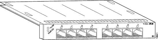
Figure 1-2 PA-A3-8E1 IMA—Faceplate View

The PA-A3-IMA can be installed in a Cisco 7100 series router, Cisco 7200 series router, Cisco 7200 VXR router, Cisco 7201 router, Cisco 7301 router, Cisco 7304 PCI Port Adapter Carrier Card in the Cisco 7304 router, Cisco 7401ASR router, VIP for Cisco 7500 series routers, or Catalyst 6000 family FlexWAN module for the Catalyst 6000 family switches and Cisco 7600 series routers. See the "Port Adapter Slot Locations on the Supported Platforms" section for the available slot locations.
Inverse Multiplexing over ATM Overview
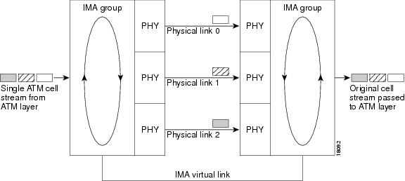
Inverse multiplexing (IMA) provides a means of access to ATM networks at rates between DS1/E1 and DS3/E3 levels (1.544 Mbps/2.048 Mbps to 44.736 Mbps/34.368 Mbps) by combining the bandwidth of multiple DS1/E1 links into groups that collectively provide higher intermediate rates. These multiple links are especially desirable in networks where DS3/E3 links are scarce.
IMA breaks up the ATM cell stream and distributes the cells over the multiple physical links of an IMA group (inverse multiplexing) and then recombines the cells into a single stream at the other end of the connection. The ATM cells are distributed in a round-robin fashion over the physical links of the IMA group, demultiplexed at the receiving IMA group, and passed in their original form to the ATM layer (see Figure 1-3). Using the multiple links of an IMA group increases the logical link bandwidth to approximately the sum of the individual link rates.
Figure 1-3 Inverse Multiplexing and Demultiplexing of ATM Cells Through IMA Groups
Features
The PA-A3-IMA has the following features:
•![]() Up to four IMA groups
Up to four IMA groups
•![]() Eight standard T1/E1 (1.544/2.048 Mbps) interfaces, with two integrated quad RJ-45 connectors
Eight standard T1/E1 (1.544/2.048 Mbps) interfaces, with two integrated quad RJ-45 connectors
•![]() Inverse multiplexing over ATM
Inverse multiplexing over ATM
•![]() Up to 4096 total virtual connections (open VCs)
Up to 4096 total virtual connections (open VCs)
•![]() Mixed mode operation, with some links in User Network Interface (UNI) mode and the others in IMA groups
Mixed mode operation, with some links in User Network Interface (UNI) mode and the others in IMA groups
•![]() Maximum differential delay of 250 milliseconds for T1 and 190 milliseconds for E1 between the individual circuits that constitute part of an IMA group
Maximum differential delay of 250 milliseconds for T1 and 190 milliseconds for E1 between the individual circuits that constitute part of an IMA group
•![]() Binary 8-zero substitution (B8ZS) line encoding for T1 and High-Density Bipolar (HDB3) line encoding for E1 in accordance with ATM UNI standards; also alternate mark inversion (AMI) line encoding for both T1 and E1
Binary 8-zero substitution (B8ZS) line encoding for T1 and High-Density Bipolar (HDB3) line encoding for E1 in accordance with ATM UNI standards; also alternate mark inversion (AMI) line encoding for both T1 and E1
•![]() Super Frame (SF) and Extended Super Frame (ESF) framing for T1; and Basic Frame, Clear E1, and CCS-CRC framing for E1
Super Frame (SF) and Extended Super Frame (ESF) framing for T1; and Basic Frame, Clear E1, and CCS-CRC framing for E1
•![]() Header Error Control (HEC)-based cell delineation for ATM framing
Header Error Control (HEC)-based cell delineation for ATM framing
•![]() Facility Data Link (FDL) processing for T1
Facility Data Link (FDL) processing for T1
•![]() Selectable Tx clock sources for T1/E1 lines
Selectable Tx clock sources for T1/E1 lines
•![]() Online insertion and removal (OIR)
Online insertion and removal (OIR)
•![]() VP shaping
VP shaping
•![]() IP-ATM class of service mapping
IP-ATM class of service mapping
•![]() These QoS classes:
These QoS classes:
–![]() UBR (unspecified bit rate)
UBR (unspecified bit rate)
–![]() VBR (variable bit rate)
VBR (variable bit rate)
–![]() ABR (available bit rate)
ABR (available bit rate)
LEDs
The PA-A3-IMA has ten LEDs: one bicolor alarm LED, one green ENABLED LED, and eight bicolor port status LEDs (see Figure 1-4).
Figure 1-4 PA-A3-IMA LEDs
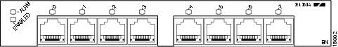
After system initialization, the ENABLED LED goes on to indicate that the port adapter has been enabled for operation.
The following conditions must be met before the PA-A3-IMA is enabled:
•![]() The PA-A3-IMA is correctly connected and is receiving power.
The PA-A3-IMA is correctly connected and is receiving power.
•![]() A valid system software image for the port adapter has been downloaded successfully.
A valid system software image for the port adapter has been downloaded successfully.
•![]() The system recognizes the PA-A3-IMA, a VIP with a PA-A3-IMA, or a Catalyst 6000 family switch or Cisco 7600 series Router with a FlexWAN module with a PA-A3-IMA.
The system recognizes the PA-A3-IMA, a VIP with a PA-A3-IMA, or a Catalyst 6000 family switch or Cisco 7600 series Router with a FlexWAN module with a PA-A3-IMA.
If any of the above conditions are not met, or if the initialization fails for other reasons, the ENABLED LED does not go on.
Table 1-1 lists LED colors and indications.
Cables, Connectors, and Pinouts
The eight DS1/E1 interface receptacles on the PA-A3-IMA are RJ-45 connectors for T1 (100 ohm) or E1 (120 ohm). All eight may be used simultaneously as ATM interfaces, or they may be used to create IMA groups.
Note ![]() After you properly connect a port to a line, it takes approximately 30 seconds for Cisco IOS software to report that the line is up.
After you properly connect a port to a line, it takes approximately 30 seconds for Cisco IOS software to report that the line is up.
Each connection supports T1 (100-ohm) or E1 (120-ohm) interfaces that meet T1.403 and ACCUNET TR62411 standards. The RJ-45 connection does not require an external transceiver. The DS1 ports are T1 interfaces that use foil twisted-pair (FTP) cables.
Note ![]() To meet VCCI Class II EMI requirements, you must use FTP cables.
To meet VCCI Class II EMI requirements, you must use FTP cables.
Figure 1-5 shows the PA-A3-IMA interface cable connector. See Chapter 4, "Configuring the PA-A3-IMA," for directions on connecting the cables of an IMA group.
Figure 1-5 PA-A3-IMA Interface Connector
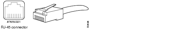
IMA Interface Cable RJ-45 Connector PinoutsTable 1-2 lists the signal pinouts and descriptions for the RJ-45 connector.
|
|
|
|
|
|---|---|---|---|
J1-1 |
RX1 ring |
TX2 ring |
J2-4 |
J1-2 |
RX tip |
TX tip |
J2-5 |
J1-3 |
RX shield |
TX shield |
NC |
J1-4 |
TX ring |
RX ring |
J2-1 |
J1-5 |
TX tip |
RX tip |
J2-2 |
J1-6 |
TX shield |
RX shield |
NC |
J1-7 |
NC3 |
NC |
|
J1-8 |
NC |
NC |
1 RX = receive 2 TX = transmit 3 NC = no connect |
Port Adapter Slot Locations on the Supported Platforms
The following sections provide port adapter slot locations and related information:
•![]() Cisco 7100 Series Routers Slot Numbering
Cisco 7100 Series Routers Slot Numbering
•![]() Cisco 7200 Series Routers and Cisco 7200 VXR Routers Slot Numbering
Cisco 7200 Series Routers and Cisco 7200 VXR Routers Slot Numbering
•![]() Cisco 7201 Router Slot Numbering
Cisco 7201 Router Slot Numbering
•![]() Cisco 7301 Router Slot Numbering
Cisco 7301 Router Slot Numbering
•![]() Cisco 7304 PCI Port Adapter Carrier Card Slot Numbering
Cisco 7304 PCI Port Adapter Carrier Card Slot Numbering
•![]() Cisco 7304 PCI Port Adapter Carrier Card Slot Numbering
Cisco 7304 PCI Port Adapter Carrier Card Slot Numbering
•![]() Cisco 7500 Series Routers VIP Slot Numbering
Cisco 7500 Series Routers VIP Slot Numbering
•![]() Catalyst 6000 Family Switches and Cisco 7600 Series Routers with FlexWAN Module Slot Numbering
Catalyst 6000 Family Switches and Cisco 7600 Series Routers with FlexWAN Module Slot Numbering
Cisco 7100 Series Routers Slot Numbering
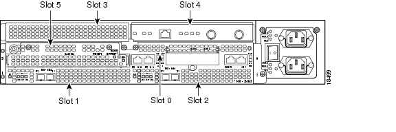
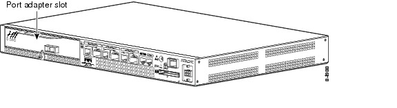
The PA-A3-IMA can be installed in port adapter slot 3 in the Cisco 7120 series routers, and in port adapter slot 4 in the Cisco 7140 series routers. Figure 1-6 shows the slot numbering on a Cisco 7120 series router. Figure 1-7 shows the slot numbering on a Cisco 7140 series router.
Figure 1-6 Port Adapter Slots in the Cisco 7120 Series Router
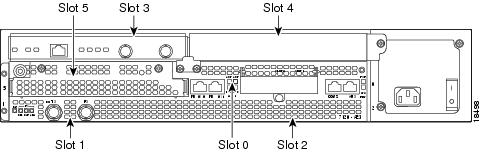
Figure 1-7 Port Adapter Slots in the Cisco 7140 Series Router
Cisco 7200 Series Routers and Cisco 7200 VXR Routers Slot Numbering
Cisco 7202 routers have two port adapter slots. The slots are numbered from left to right. You can place a port adapter in either of the slots (slot 1 or slot 2). The Cisco 7202 router is not shown.
Cisco 7204 routers and Cisco 7204VXR routers have four slots for port adapters, and one slot for an input/output (I/O) controller. The slots are numbered from the lower left to the upper right, beginning with slot 1 and continuing through slot 4. You can place a port adapter in any of the slots (slot 1 through slot 4). Slot 0 is always reserved for the I/O controller. The Cisco 7204 router and Cisco 7204VXR are not shown.
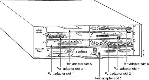
Cisco 7206 routers and Cisco 7206VXR routers (including the Cisco 7206 and Cisco 7206VXR routers as router shelves in a Cisco AS5800 Universal Access Server) have six slots for port adapters, and one slot for an input/output (I/O) controller. The slots are numbered from the lower left to the upper right, beginning with slot 1 and continuing through slot 6. You can place a port adapter in any of the six slots (slot 1 through slot 6). Slot 0 is always reserved for the I/O controller.
Figure 1-8 shows the slot numbering on a Cisco 7206 router. The Cisco 7206VXR router is not shown.
Figure 1-8 Port Adapter Slots in the Cisco 7206 Router
Cisco 7201 Router Slot Numbering
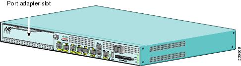
Figure 1-9 shows the front view of a Cisco 7201 router with a port adapter installed. There is only one port adapter slot (slot 1) in a Cisco 7201 router.
Figure 1-9 Port Adapter Slot in the Cisco 7201 Router
Cisco 7301 Router Slot Numbering
Figure 1-10 shows the front view of a Cisco 7301 router with a port adapter installed. There is only one port adapter slot (slot 1) in a Cisco 7301 router.
Figure 1-10 Port Adapter Slot in the Cisco 7301 Router
Cisco 7304 PCI Port Adapter Carrier Card Slot Numbering
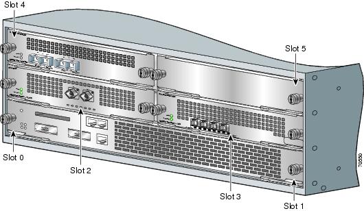
The Cisco 7304 PCI Port Adapter Carrier Card installs in Cisco 7304 router module slots 2 through 5. Figure 1-11 shows a Cisco 7304 PCI Port Adapter Carrier Card with a port adapter installed. The Cisco 7304 PCI Port Adapter Carrier Card accepts one single-width port adapter.
Figure 1-12 shows the module slot numbering on a Cisco 7304 router. The port adapter slot number is the same as the module slot number. Slot 0 and slot 1 are reserved for the NPE module or NSE module.
Figure 1-11 Cisco 7304 PCI Port Adapter Carrier Card—Port Adapter Installed
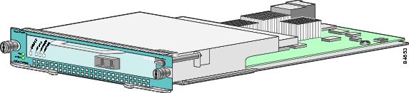
Figure 1-12 Module Slots on the Cisco 7304 Router
Cisco 7401ASR Router Slot Numbering
Figure 1-13 shows the front view of a Cisco 7401ASR router with a port adapter installed. There is only one port adapter slot (slot 1) in a Cisco 7401ASR router.
Note ![]() PA-A3-8E1 IMA is not supported on Cisco 7401ASR routers.
PA-A3-8E1 IMA is not supported on Cisco 7401ASR routers.
Figure 1-13 Port Adapter Slot in the Cisco 7401ASR Router
Cisco 7500 Series Routers VIP Slot Numbering
Port adapters are supported on the VIPs (versatile interface processors) used in Cisco 7500 series routers. In the Cisco 7505 router, the VIP motherboard is installed horizontally in the VIP slot. In the Cisco 7507 router and Cisco 7513 router, the VIP motherboard is installed vertically in the VIP slot. A port adapter can be installed in either bay (port adapter slot 0 or 1) on the VIP. The bays are numbered from left to right on the VIP. Figure 1-14 shows the slot numbering on a VIP.
Figure 1-14 VIP Slot Locations—Partial View, Horizontal Orientation
Cisco 7505 routers have four slots for port adapters, and one slot for an RSP. The slots are numbered from bottom to top. You can place a port adapter in any of the VIP interface slots (slot 0 through 3). One slot is always reserved for the RSP. Figure 1-15 shows the slot numbering on a Cisco 7505 router.
Figure 1-15 VIP Slots in the Cisco 7505 Router
Cisco 7507 routers have five slots for port adapters, and two slots for RSPs. The slots are numbered from left to right. You can place a port adapter in any of the VIP interface slots (slot 0, 1, 4, 5, or 6). Slots 2 and 3 are always reserved for RSPs. The Cisco 7507 router is not shown.
Cisco 7513 routers have eleven slots for port adapters, and two slots for RSPs. The slots are numbered from left to right. You can place a port adapter in any of the VIP interface slots (slots 0 through 5, or slots 9 through 12). Slots 6 and 7 are always reserved for RSPs. The Cisco 7513 router is not shown.
Catalyst 6000 Family Switches and Cisco 7600 Series Routers with FlexWAN Module Slot Numbering
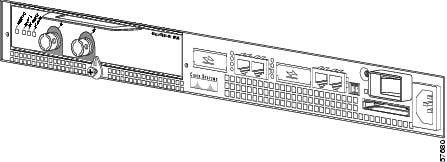
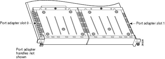
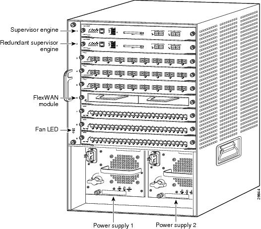
The FlexWAN module can be installed in any slot of a Catalyst 6000 family switch or a Cisco 7600 series router except slot 1, which is reserved for the supervisor engine. Port adapters can be installed into either module bay 0 or module bay 1 on the FlexWAN module. Figure 1-16 shows a FlexWAN module with two blank port adapters installed. The bays are numbered from left to right on the FlexWAN module. The slot numbering is the same for Catalyst 6000 family switches and Cisco 7600 series routers.
Note ![]() Slot 1 is reserved for the supervisor engine. If a redundant supervisor engine is used, it would go in slot 2; otherwise, slot 2 can be used for other modules.
Slot 1 is reserved for the supervisor engine. If a redundant supervisor engine is used, it would go in slot 2; otherwise, slot 2 can be used for other modules.
Figure 1-16 Catalyst 6000 Family Switch with Port Adapters Installed on FlexWAN Module
Cisco 7603 routers have two slots for port adapters. The slots are numbered from top to bottom. You can place the port adapters in either of the FlexWAN module slots (slot 2 or 3). Slot 1 is always reserved for the supervisor engine. The Cisco 7603 router is not shown.
Cisco 7606 routers have five slots for port adapters. The slots are numbered from top to bottom. You can place the port adapters in any of the FlexWAN module slots (slots 2 through 6). Slot 1 is always reserved for the supervisor engine. The Cisco 7606 router is not shown.
Cisco 7609 routers have eight slots for port adapters. The slots are numbered from right to left. You can place the port adapters in any of the FlexWAN module slots (slots 2 through 9). Slot 1 is always reserved for the supervisor engine. The Cisco 7609 router is not shown.
Cisco 7613 routers have twelve slots for port adapters. The slots are numbered from top to bottom. You can place the port adapters in any of the FlexWAN module slots (slots 2 through 13). Slot 1 is always reserved for the supervisor engine. The Cisco 7613 router is not shown.
Note ![]() Some of the slots used for the FlexWAN module on the Cisco 7606 router, Cisco 7609 router, and Cisco 7613 router can also be used for other supervisor engines, RSPs, or OSMs. For details, refer to the Cisco 7600 Series Router Installation Guide at the following URL:
Some of the slots used for the FlexWAN module on the Cisco 7606 router, Cisco 7609 router, and Cisco 7613 router can also be used for other supervisor engines, RSPs, or OSMs. For details, refer to the Cisco 7600 Series Router Installation Guide at the following URL:
http://www.cisco.com/en/US/products/hw/routers/ps368/products_installation_guide_book09186a008080269a.html
Identifying Interface Addresses
This section describes how to identify interface addresses for the PA-A3-IMA in supported platforms. Interface addresses specify the actual physical location of each interface on a router or switch.
Interfaces on a PA-A3-IMA installed in a router maintain the same address regardless of whether other port adapters are installed or removed. However, when you move a port adapter to a different slot, the first number in the interface address changes to reflect the new port adapter slot number.
Interfaces on a PA-A3-IMA installed in a VIP or FlexWAN module maintain the same address regardless of whether other interface processors or modules are installed or removed. However, when you move a VIP or FlexWAN module to a different slot, the interface processor or module slot number changes to reflect the new interface processor or module slot.
Note ![]() Interface ports are numbered from left to right starting with 0.
Interface ports are numbered from left to right starting with 0.
The following subsections describe the interface address formats the supported platforms:
•![]() Cisco 7100 Series Routers Interface Addresses
Cisco 7100 Series Routers Interface Addresses
•![]() Cisco 7200 Series Routers and Cisco 7200VXR Series Routers Interface Addresses
Cisco 7200 Series Routers and Cisco 7200VXR Series Routers Interface Addresses
•![]() Cisco 7201 Router Slot Numbering
Cisco 7201 Router Slot Numbering
•![]() Cisco 7301 Router Interface Addresses
Cisco 7301 Router Interface Addresses
•![]() Cisco 7304 PCI Port Adapter Carrier Card Interface Addresses
Cisco 7304 PCI Port Adapter Carrier Card Interface Addresses
•![]() Cisco 7401ASR Router Interface Addresses
Cisco 7401ASR Router Interface Addresses
•![]() Cisco 7500 Series Routers VIP Interface Addresses
Cisco 7500 Series Routers VIP Interface Addresses
•![]() Catalyst 6000 Family Switches and Cisco 7600 Series Routers with FlexWAN Module Interface Addresses
Catalyst 6000 Family Switches and Cisco 7600 Series Routers with FlexWAN Module Interface Addresses
Table 1-3 summarizes the interface address formats for the supported routers.
|
|
|
|
|
|---|---|---|---|
Cisco 7120 series router |
Port-adapter-slot-number/interface-port-number |
Port adapter slot—always 3 Interface port—0 through 7 |
3/1 |
Cisco 7140 series router |
Port-adapter-slot-number/interface-port-number |
Port adapter slot—always 4 Interface port—0 through 7 |
4/0 |
Cisco 7200 series routers and Cisco 7200 VXR routers (7202, 7204, 7204VXR, 7206, and 7206VXR) |
Port-adapter-slot-number/interface-port-number |
Port adapter slot—11 through 6 (depends on the number of slots in the router) Interface port—0 through 7 |
1/0 |
Cisco 7201 router |
Port-adapter-slot-number/interface-port number |
Port adapter slot—always 1 Interface port—0 through 7 |
1/0 |
Cisco 7301 router |
Port-adapter-slot-number/interface-port number |
Port adapter slot—always 1 Interface port—0 through 7 |
1/0 |
Cisco 7304 PCI port adapter carrier card in Cisco 7304 router |
Module-slot-number/interface-port-number |
Module slot—2 through 5 Interface port—0 through 7 |
3/0 |
Cisco 7401ASR router |
Port-adapter-slot-number/interface-port number |
Port adapter slot—always 1 Interface port—0 through 7 |
1/0 |
Cisco 7500 series routers (7505, 7507, 7513) with VIP |
Interface-processor-slot-number/port-adapter |
Interface processor slot—0 through 12 (depends on the number of slots in the router) Port adapter slot— 0 or 1 Interface port—0 through 7 |
3/1/0 |
FlexWAN or Enhanced FlexWAN module in Catalyst 6000 family switches or Cisco 7600 series routers (7603, 7606, 7609, 7613) |
Module-slot-number/port-adapter-bay-number/ |
Module slot number—22 through 13 (depends on the number of slots in the switch/router) Port adapter bay—0 or 1 Interface port—0 through 7 |
3/0/0 |
1 Port adapter slot 0 is reserved for the Fast Ethernet port on the I/O controller (if present). 2 Slot 1 is reserved for the supervisor engine. If a redundant supervisor engine is used, it must go in slot 2; otherwise, slot 2 can be used for other modules. |
Cisco 7100 Series Routers Interface Addresses
In Cisco 7120 series router, port adapters are installed in port adapter slot 3. See Figure 1-6. In the Cisco 7140 series router, port adapters are installed in port adapter slot 4. See Figure 1-7.
The interface address is composed of a two-part number in the format port-adapter-slot-number/interface-port-number. See Table 1-3. For example, if an eight-port PA-A3-IMA is installed on a Cisco 7120 router, the interface addresses would be 3/0 through 3/7 (port adapter slot 3, and interfaces 0,1, 2, 3, 4, 5, 6, and 7). If an eight-port PA-A3-IMA is installed on a Cisco 7140 router, the interface addresses would be 4/0 through 4/7 (port adapter slot 4, and interfaces 0,1, 2, 3, 4, 5, 6, and 7).
Cisco 7200 Series Routers and Cisco 7200VXR Series Routers Interface Addresses
In Cisco 7200 series routers and Cisco 7200 VXR routers, port adapter slots are numbered from the lower left to the upper right, beginning with slot 1 and continuing through slot 2 for the Cisco 7202, slot 4 for the Cisco 7204 and Cisco 7204VXR, and slot 6 for the Cisco 7206 and Cisco 7206VXR. Port adapters can be installed in any available port adapter slot from 1 through 6 (depending on the number of slots in the router). (Slot 0 is reserved for the I/O controller.) See Figure 1-8.
Figure 1-17 shows a PA-A3-IMA in port adapter slot 3 of the Cisco 7206 router.
Figure 1-17 PA-A3-IMA in Slot 3 of a Cisco 7206 Router
The interface address is composed of a two-part number in the format port-adapter-slot-number/interface-port-number. See Table 1-3. For example, if an eight-port PA-A3-IMA is installed in slot 3 of a Cisco 7200 series router (as shown in Figure 1-17 for a Cisco 7206 router), the interface addresses would be 3/0 through 3/7 (port adapter slot 3 and interfaces 0 through 7).
Cisco 7201 Router Interface Addresses
In the Cisco 7201 router, only one slot accepts port adapters and it is numbered as slot 1. See Figure 1-9.
The interface address is composed of a two-part number in the format port-adapter-slot-number/interface-port-number. See Table 1-3. For example, if an eight-port PA-A3-IMA is installed in a Cisco 7201 router, the interface addresses would be 1/0 through 1/7.
Cisco 7301 Router Interface Addresses
In the Cisco 7301 router, only one slot accepts port adapters and it is numbered as slot 1. See Figure 1-10.
The interface address is composed of a two-part number in the format port-adapter-slot-number/interface-port-number. See Table 1-3. For example, if an eight-port PA-A3-IMA is installed in a Cisco 7301 router, the interface addresses would be 1/0 through 1/7.
Cisco 7304 PCI Port Adapter Carrier Card Interface Addresses
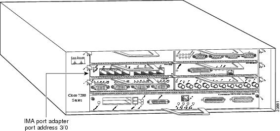
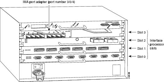
In the Cisco 7304 router, port adapters are installed in a Cisco 7304 PCI port adapter carrier card, which installs in Cisco 7304 router module slots 2 through 5. The port adapter slot number is the same as the module slot number. See Figure 1-11 and Figure 1-12.
The interface address is composed of a two-part number in the format module-slot-number/interface-port-number. See Table 1-3. For example, if an eight-port PA-A3-IMA is installed in the Cisco 7304 PCI port adapter carrier card in Cisco 7304 router module slot 3, the interface addresses would be 3/0 through 3/7.
Cisco 7401ASR Router Interface Addresses
In the Cisco 7401ASR router, only one slot accepts port adapters and it is numbered as slot 1. See Figure 1-13.
The interface address is composed of a two-part number in the format port-adapter-slot-number/interface-port-number. See Table 1-3. For example, if an eight-port PA-A3-IMA is installed in a Cisco 7401ASR router, the interface addresses would be 1/0 through 1/7.
Cisco 7500 Series Routers VIP Interface Addresses
In Cisco 7000 series routers and Cisco 7500 series routers, port adapters are installed on a versatile interface processor (VIP), which installs in interface processor slots 0 through 12 (depending on the number of slots in the router). The port adapter can be installed in either bay (port adapter slot 0 or 1) on the VIP. See Figure 1-14 and Figure 1-15.
The interface address for the VIP is composed of a three-part number in the format interface-processor-slot-number/port-adapter-slot-number/interface-port-number. See Table 1-3.
The first number identifies the slot in which the VIP is installed (slot 0 through 12, depending on the number of slots in the router).
The second number identifies the bay (port adapter slot) on the VIP in which the port adapter is installed (0 or 1). The bays are numbered from left to right on the VIP.
The third number identifies the physical port number (interface port number) on the port adapter. The port numbers always begin at 0 and are numbered from left to right. The number of additional ports depends on the number of ports on the port adapter. The PA-A3-IMA is an eight-port port adapter, therefore the port can be 0 through 7.
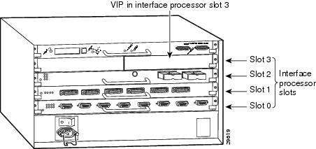
Figure 1-18 shows a PA-A3-IMA in port adapter slot 3 of the Cisco 7505 router.
Figure 1-18 PA-A3-IMA in Slot 3 of a Cisco 7505 Shown
For example, if an eight-port PA-A3-IMA is installed in a VIP in interface processor slot 3, port adapter slot 1 (as shown in Figure 1-18 for a Cisco 7505 router), the interface addresses would be 3/1/0 through 3/1/7 (interface processor slot 3, port adapter slot 1, and interfaces 0, 1, 2, 3, 4, 5, 6, and 7).
Note ![]() Although the processor slots in the seven-slot Cisco 7507 and thirteen-slot Cisco 7513 and Cisco 7576 are vertically oriented and those in the five-slot Cisco 7505 are horizontally oriented, all Cisco 7500 series routers use the same method for slot and port numbering.
Although the processor slots in the seven-slot Cisco 7507 and thirteen-slot Cisco 7513 and Cisco 7576 are vertically oriented and those in the five-slot Cisco 7505 are horizontally oriented, all Cisco 7500 series routers use the same method for slot and port numbering.
Catalyst 6000 Family Switches and Cisco 7600 Series Routers with FlexWAN Module Interface Addresses
In Catalyst 6000 family switches and Cisco 7600 series routers, port adapters are installed in a FlexWAN module, which installs in module slots 2 through 13 (depending on the number of slots in the router). The port adapter can be installed in either bay (port adapter bay 0 or 1) on the FlexWAN module. See Figure 1-16.
The interface address is composed of a three-part number in the format module-slot-number/port-adapter-bay-number/interface-port-number. See Table 1-3.
The first number identifies the module slot of the chassis in which the FlexWAN module is installed (slot 2 through slot 3, 6, 9, or 13 depending on the number of slots in the chassis). These module slots are generally numbered from top to bottom, starting with 1. The Cisco 7609 is the exception with slots numbered right to left, starting with 1.
The second number identifies the bay of the FlexWAN module in which the port adapter is installed (0 or 1). The bays are numbered from left to right on the FlexWAN module.
The third number identifies the physical port number on the port adapter. The PA-A3-IMA is an eight-port port adapter, therefore the port can be 0 through 7.
For example, if an eight-port PA-A3-IMA is installed in the FlexWAN module, which is inserted in module slot 3, port adapter bay 0, the interface addresses would be 3/0/0 through 3/0/7 (interface processor slot 3, port adapter slot 0, and interfaces 0, 1, 2, 3, 4, 5, 6, and 7). If the same port adapter is in port adapter bay 1 on the FlexWAN module, the interface addresses would be 3/1/0 through 3/1/7 (interface processor slot 3, port adapter slot 1, and interfaces 0, 1, 2, 3, 4, 5, 6, and 7).
Note ![]() The FlexWAN module physical port address begins with slot 0, which differs from the conventional Catalyst 6000 family port address, which begins with slot 1.
The FlexWAN module physical port address begins with slot 0, which differs from the conventional Catalyst 6000 family port address, which begins with slot 1.
 Feedback