Installation

Installation Overview

The following installation workflow summarizes the steps that are involved in creating a Stretched Cluster, using the HX Data Platform Installer.

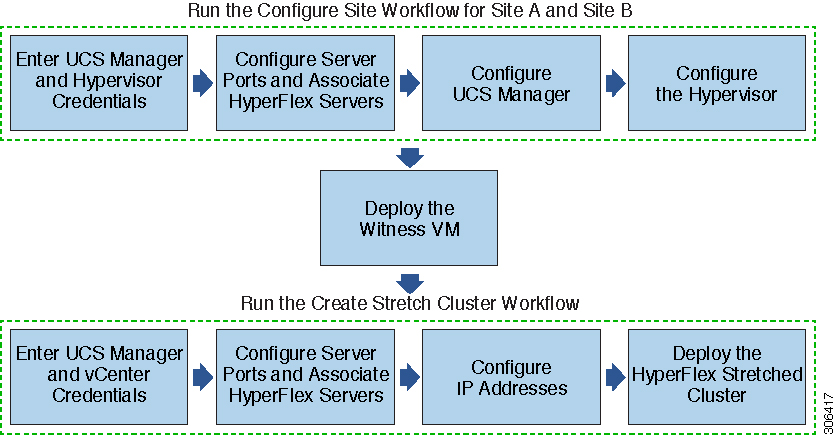
Follow this workflow during installation:

Step

Description

Reference

Create the Stretched Cluster sites—Run the Configure Site workflow for Site A and Site B.

Log in to the HX Data Platform Installer. Enter UCS Manager credentials and Hypervisor credentials for both the sites.

Enter Credentials

Configure the server ports and associate HyperFlex servers.

Associate HyperFlex Servers

Configure VLAN, MAC Pool, 'hx-ext-mgmt' IP Pool for Out-of-Band CIMC, inband CIMC, iSCSi Storage, and FC Storage.

Configure UCS Manager

Configure the Hypervisor.

Configure Hypervisor

Download and deploy the Witness VM.

Note 

A witness VM is mandatory in a HyperFlex Stretched Cluster environment.

Deploying the Witness Node

Create your HyperFlex Stretched Cluster—Run the Create Stretch Cluster workflow.

Enter UCS Manager Credentials for Site A and Site B, and vCenter credentials.

Enter Credentials

Configure the server ports and associate HyperFlex servers.

Associate HyperFlex Servers

Configure IP addresses.

Configure IP Addresses

Deploy the HyperFlex Stretched Cluster.

Deploy a HyperFlex Stretched Cluster

Create the Stretched Cluster Sites

Before you begin

  • Complete the prerequisites. Refer to the Preinstallation Checklist for more details.

  • Download and deploy the Witness VM for each cluster.

Use the following procedure to install and configure a Cisco HyperFlex Stretched Cluster using the HX Data Platform Installer.

Procedure


Step 1

Log in to the HX Data Platform Installer.

Step 2

On the Workflow page, from the Create Cluster drop-down list, select Stretch Cluster. Click Continue.

Step 3

On the Credentials page, enter UCS Manager and Hypervisor credentials. See Enter Credentials for more details.

Step 4

On the Server Selection page, configure the server ports and associate HyperFlex servers. See Associate HyperFlex Servers for more details.

Step 5

On the UCSM Configuration page, configure VLAN, MAC Pool, 'hx-ext-mgmt' IP Pool for Out-of-Band CIMC, iSCSi Storage, and FC Storage. See Configure UCS Manager for more details.

Step 6

On the Hypervisor Configuration page, configure the subnet mask, gateway, and complete the hypervisor settings. See Configure Hypervisor for more details.

Step 7

Click Configure Site to begin cluster creation. The Progress page displays the progress of various configuration tasks.

Caution 

Do not skip validation warnings.

See the Warnings section for more details.


What to do next

Using the HX Data Platform Installer, proceed to create your HyperFlex stretch cluster. See Create Your HyperFlex Stretched Cluster for more details.

Enter Credentials

Enter UCS Manager credentials and hypervisor credentials for both the sites across the Stretched Cluster.

Before you begin

  • Complete the installation prerequisites. Refer to the Preinstallation Checklist for more details.

  • Download and deploy the Witness VM.

Procedure


Step 1

Log in to the HX Data Platform Installer with root user credentials. For first time log in, you will be prompted to change the default password set in the factory.

  1. In a browser, enter the URL for the VM where HX Data Platform Installer was installed.

  2. Enter the following login credentials.

    • Username: root

    • Password: Cisco123

  3. Read the EULA, select the I accept the terms and conditions checkbox, and click Login.

Step 2

In the Change factory default password screen, complete the following fields, and click Change Password & Login.

Field

Description

New password

Enter a new hypervisor password.

Re-enter new password

Re-enter the new hypervisor password.

Step 3

On the Workflow page, from the Create Cluster drop-down list, select Stretch Cluster. Click Continue.

Step 4

On the Credentials page, select Configure Site.

To perform cluster creation, you can import a JSON configuration file with the required configuration data. The following two steps are optional if importing a JSON file, otherwise you can input data into the required fields manually.

Note 

For a first-time installation, contact your Cisco representative to procure the factory preinstallation JSON file.

  1. Click Select a file and choose your JSON file to load the configuration. Select Use Configuration.

  2. An Overwrite Imported Values dialog box displays if your imported values for Cisco UCS Manager are different. Select Use Discovered Values.

Step 5

Enter the following credentials for UCS Manager:

UCS Manager Credentials for this site

Field

Description

UCS Manager Host Name field

Enter the UCS Manager FQDN or IP address.

For example, 10.193.211.120.

UCS Manager User Name field

Enter the administrative level username.

For example, <admin>.

Password field

Enter the administrative level password.

For example, <root>.

Site Name field

Specify a unique site name.

Step 6

Enter the following credentials for the Hypervisor:

Hypervisor Credentials

Field

Description

Admin User Name field

Enter the administrative username.

For example, <admin> username.

The username is root for factory nodes.

The hypervisor on this node uses the factory default password check box

Select the check box, if you are changing the factory default password for the hypervisor.

To enter the current hypervisor password, uncheck this check box. You can now enter the hypervisor password in the Enter current hypervisor password field.

New Password

Create a new password for the hypervisor.

Important 

You are required to change the factory default password.

Confirm New Password

Reenter the new password for the hypervisor.

Step 7

Click Continue to begin associating HyperFlex Servers. See Associate HyperFlex Servers.


Associate HyperFlex Servers

On the Server Selection page, the Configuration pane on the right displays a detailed list of the Credentials used. The Server Selection page displays a list of unassociated HX servers under the Unassociated tab, and the list of discovered servers under the Associated tab.

Field

Description

Locator LED column

Turn on to locate a server.

Server Name column

Name that is assigned to the server.

Status column

  • Inaccessible

  • Ok

Model column

Displays the server model.

Serial column

Displays the serial number of the server.

Service Profile column [Only for Associated Servers]

Service profile that is assigned to the server.

Actions drop-down list

  • Launch KVM Console—Choose this option to launch the KVM Console directly from the HX Data Platform Installer.

  • Disassociate Server—Choose this option to remove a service profile from that server.

Before you begin

Ensure that you completed entering UCS Manager, vCenter, and Hypervisor credentials on the Credentials page. See Enter Credentials.

Procedure


Step 1

Click the Configure Server Ports button to discover any new HX nodes. In the Configure Server Ports dialog box, list all ports to be configured as server ports. Click Configure.

Note 

Typically, the server ports are configured in Cisco UCS Manager before you start the configuration.

Step 2

Select the servers under the Unassociated tab to include in the HyperFlex cluster.

If HX servers do not appear in this list, check Cisco UCS Manager and ensure that they have been discovered.

Note 

If there are no unassociated servers, the following error message is displayed:

No unassociated servers found. Login to UCS Manager and ensure server ports are enabled. 
Step 3

Click Continue to configure UCS Manager. See Configure UCS Manager .


Configure UCS Manager

On the UCSM Configuration page, you can configure VLAN, MAC Pool, 'hx-ext-mgmt' IP Pool for Out-of-Band CIMC, iSCSi Storage, and FC Storage.

Before you begin

Associate servers on the HyperFlex cluster. See Associate HyperFlex Servers.

Procedure


Step 1

In the VLAN Configuration section, complete the following fields:

Note 

Use separate subnet and VLANs for each of the following networks.

Field

Description

VLAN for Hypervisor and HyperFlex management

VLAN Name field

hx-inband-mgmt

VLAN ID field

Default—3091

VLAN for HyperFlex storage traffic

VLAN Name field

hx-storage-data

VLAN ID field

Default—3092

VLAN for VM vMotion

VLAN Name field

hx-vmotion

VLAN ID field

Default—3093

VLAN for VM Network

VLAN Name field

vm-network

VLAN ID(s) field

Default—3094

A comma-separated list of guest VLANs.

Step 2

In the MAC Pool section, configure the MAC Pool Prefix by adding in two more hex characters (0-F).

Note 

Select a prefix that is not used with any other MAC address pool across all UCS domains.

Example:
00:25:B5:A0.
Step 3

In the 'hx-ext-mgmt' IP Pool for Out-of-Band CIMC section, complete the following fields:

Field

Description

IP Blocks field

The range of IP addresses designated for the HyperFlex nodes. The IP addresses can be a comma-separated list of values for the guest VLANs.

For example, 10.193.211.124-127, 10.193.211.158-163.

Subnet Mask field

Set the subnet to the appropriate level to limit and control IP addresses.

For example, 255.255.0.0.

Gateway field

Enter the IP address.

For example, 10.193.0.1.

Step 4

If you want to add external storage, configure iSCSI Storage by completing the following fields:

Field

Description

Enable iSCSI Storage check box

Select to configure iSCSI storage.

VLAN A Name field

Name of the VLAN associated with the iSCSI vNIC, on the primary fabric interconnect (FI-A).

VLAN A ID field

ID of the VLAN associated with the iSCSI vNIC, on the primary fabric interconnect (FI-A).

VLAN B Name field

Name of the VLAN associated with the iSCSI vNIC, on the subordinate fabric interconnect (FI-B).

VLAN B ID field

ID of the VLAN associated with the iSCSI vNIC, on the subordinate fabric interconnect (FI-A).

Step 5

If you want to add external storage, configure FC Storage by completing the following fields:

Field

Description

Enable FC Storage check box

Select to enable FC Storage.

WWxN Pool field

A WWN pool that contains both WW node names and WW port names. For each fabric interconnect, a WWxN pool is created for WWPN and WWNN.

VSAN A Name field

The name of the VSAN for the primary fabric interconnect (FI-A).

Default—hx-ext-storage-fc-a.

VSAN A ID field

The unique identifier assigned to the network for the primary fabric interconnect (FI-A).

Caution 

Do not enter VSAN IDs that are currently used on the UCS or HyperFlex system. If you enter an existing VSAN ID in the installer which utilizes UCS zoning, zoning will be disabled in your existing environment for that VSAN ID.

VSAN B Name field

The name of the VSAN for the subordinate fabric interconnect (FI-B).

Default—hx-ext-storage-fc-b.

VSAN B ID field

The unique identifier assigned to the network for the subordinate fabric interconnect (FI-B).

Caution 

Do not enter VSAN IDs that are currently used on the UCS or HyperFlex system. If you enter an existing VSAN ID in the installer which utilizes UCS zoning, zoning will be disabled in your existing environment for that VSAN ID.

Step 6

In the Advanced section, do the following:

Field

Description

UCS Server Firmware Version drop-down list

Select the UCS server firmware version to associate with the HX servers from the drop-down list. The UCS firmware version must match the UCSM version. See the latest Cisco HX Data Platform Release Notes for more details.

For example, 3.2(1d).

HyperFlex Cluster Name field

Specify a user-defined name. The HyperFlex cluster name is applied to a group of HX Servers in a given cluster. The HyperFlex cluster name adds a label to service profiles for easier identification.

Org Name field

Specify a unique Org Name to ensure isolation of the HyperFlex environment from the rest of the UCS domain.

Step 7

Click Continue to configure the Hypervisor. See Configure Hypervisor.


Configure Hypervisor


Note

Review the VLAN, MAC pool, and IP address pool information on the Hypervisor Configuration page, in the Configuration pane. These VLAN IDs may be changed by your environment. By default, the HX Data Platform Installer sets the VLANs as non-native. Configure the upstream switches to accommodate the non-native VLANs by appropriately applying a trunk configuration.


Attention

You can skip configuring Hypervisor in case of a reinstall, if ESXi networking has been completed.

Before you begin

Configure VLAN, MAC Pool, and 'hx-ext-mgmt' IP Pool for Out-of-Band CIMC. If you are adding external storage, configure iSCSI Storage and FC Storage. Select the UCS Server Firmware Version and assign a name for the HyperFlex Stretched Cluster. See Configure UCS Manager.

Procedure


Step 1

In the Configure Common Hypervisor Settings section, complete the following fields:

Field

Description

Subnet Mask field

Set the subnet mask to the appropriate level to limit and control IP addresses.

For example, 255.255.0.0.

Gateway field

IP address of gateway.

For example, 10.193.0.1.

DNS Server(s) field

IP address for the DNS Server.

Note 
  • If you do not have a DNS server, do not enter a hostname in any of the fields on the Cluster Configuration page of the HX Data Platform Installer. Use only static IP addresses and hostnames for all ESXi hosts.

  • If you are providing more than one DNS server, check carefully to ensure that both DNS servers are correctly entered, separated by a comma.

Step 2

On the Hypervisor Settings section, select Make IP Addresses and Hostnames Sequential to make the IP addresses sequential. Complete the following fields:

Note 

You can rearrange the servers using drag and drop.

Field

Description

Name column

Name assigned to the server.

Locator LED column

Turn on to locate a server.

Serial column

Displays the serial number of the server.

Static IP Address column

Input static IP addresses and hostnames for all ESXi hosts.

Hostname column

Do not leave the hostname fields empty.

Step 3

Click Configure Site to begin cluster creation. The Progress page displays the progress of various configuration tasks.

Caution 

Do not skip validation warnings.

See the Warnings section for more details.


What to do next

Run the Create Stretch Cluster workflow from the HX Data Platform Installer to create your HyperFlex Stretched Cluster. See Create Your HyperFlex Stretched Cluster for more details.

Create Your HyperFlex Stretched Cluster

Use the following procedure to create a Cisco HyperFlex Stretched Cluster using the Cisco HX Data Platform Installer.

Before you begin

  • Complete the prerequisites. Refer to the Preinstallation Checklist for more details.

  • Ensure that you run the Configure Site workflow for both sites.

  • Download and deploy the Witness VM.

Procedure


Step 1

Log in to the Cisco HX Data Platform Installer.

Step 2

On the Workflow page, from the Create Cluster drop-down list, select Stretch Cluster. Click Continue.

Step 3

On the Credentials page, select Create Stretch Cluster. Enter UCS Manager credentials for site 1 and site 2. Enter vCenter credentials. Click Continue. See Enter Credentials for more details.

Step 4

On the Server Selection page, configure the server ports and associate HyperFlex servers. See Associate HyperFlex Servers for more details.

Step 5

On the IP Addresses page, configure the IP addresses to be applied to the storage cluster. See Configure IP Addresses for more details.

Step 6

On the Cluster Configuration page, configure and deploy the HyperFlex stretched cluster. See Deploy a HyperFlex Stretched Cluster for more details.

Step 7

Click Start to begin deploying the stretched cluster. The Progress page displays the progress of the various configuration tasks.


What to do next

Click Launch HyperFlex Connect to manage your HyperFlex Stretched Cluster.

Enter Credentials

Enter UCS manager credentials for site 1 and site 2, and enter credentials for the vCenter.

Before you begin

Procedure


Step 1

Log in to the Cisco HX Data Platform Installer.

  1. In your web browser, enter the IP address or the node name for the Cisco HX Data Platform Installer VM. Click Accept or Continue to bypass any SSL certificate errors. On the Cisco HX Data Platform Installer login page, verify the Cisco HX Data Platform Installer Build ID in the lower right corner of the login screen.

  2. In the login page, enter the following credentials:

    Username: root

    Password (Default): Cisco123

    Important 

    Systems ship with a default password of Cisco123 that must be changed during installation. You cannot continue installation unless you specify a new user supplied password.

  3. Read the EULA, check the I accept the terms and conditions check box, and click Login.

Step 2

On the Workflow page, from the Create Cluster drop-down list, select Stretch Cluster. Click Continue.

Step 3

On the Credentials page, select Create Stretch Cluster.

Step 4

Enter the following UCS Manager credentials for Site 1 and Site 2.

To perform cluster creation, you can import a JSON configuration file with the required configuration data. The following two steps are optional if importing a JSON file, otherwise you can input data into the required fields manually.

Note 

For a first-time installation, contact your Cisco representative to procure the factory preinstallation JSON file.

  1. Click Select a file and choose your JSON file to load the configuration. Select Use Configuration.

  2. An Overwrite Imported Values dialog box displays if your imported values for Cisco UCS Manager are different. Select Use Discovered Values.

UCS Manager Credentials for Site 1

Field

Description

UCS Manager Hostname field

UCS Manager FQDN or IP address for site 1.

For example, 10.193.211.120.

User Name field

Enter the administrative level username.

For example, <admin> username.

Password field

Enter the administrative level password.

Enter the <root> password.

Site Name field

Specify a unique site name.

Org Name field

Specify a unique org name, to ensure isolation of the HyperFlex environment from the rest of the UCS domain.

UCS Manager Credentials for Site 2

Field

Description

UCS Manager Host Name field

Enter the UCS Manager FQDN or IP address for site 2.

For example, 10.193.211.120.

User Name field

Enter the administrative level username.

For example, <admin> username.

Password field

Enter the administrative level password.

Enter the <root> password.

Site Name field

Specify a unique site name.

Org Name field

Specify a unique org name. This ensures isolation of the HyperFlex environment from the rest of the UCS domain.

Step 5

Enter the following credentials for the vCenter.

vCenter Credentials

Field

Description

vCenter Server field

Enter the vCenter server FQDN or IP address.

For example, 10.193.211.120.

Note 
  • vCenter Server input is optional if building a nested vCenter. See the Nested vCenter TechNote for more details. A vCenter server is required before the cluster can be made operational.

  • The vCenter address and credentials must have root level administrator permissions to the vCenter.

User Name field

Enter the administrative username.

For example, administrator@vsphere.local.

Admin Password field

Enter the administrative level password.

Enter the <root> password.

Step 6

Click Continue to begin associating HyperFlex servers. See Associate HyperFlex Servers.


Associate HyperFlex Servers

On the Server Selection page, the Configuration pane on the right displays a detailed list of the Credentials used. The Server Selection page displays a list of unassociated HX servers under the Unassociated tab, and the list of discovered servers under the Associated tab.

Field

Description

Locator LED column

Turn on to locate a server.

Server Name column

Name that is assigned to the server.

Status column

  • Inaccessible—

  • Ok—

Model column

Displays the server model.

Serial column

Displays the serial number of the server.

Service Profile column [Only for Associated Servers]

Service profile that is assigned to the server.

Actions column

  • Launch KVM Console—Choose this option to launch the KVM Console directly from the HX Data Platform Installer.

  • Disassociate Server—Choose this option to remove a service profile from that server.

Before you begin

Ensure that you completed entering UCS Manager, vCenter, and Hypervisor credentials on the Credentials page. See Enter Credentials.

Procedure


Step 1

Click the Configure Server Ports button to discover any new HX nodes. In the Configure Server Ports dialog box, list all ports to be configured as server ports. Click Configure.

Note 

Typically, the server ports are configured in Cisco UCS Manager before you start the configuration.

Step 2

Select the servers under the Unassociated tab to include in the HyperFlex cluster.

If HX servers do not appear in this list, check Cisco UCS Manager and ensure that they have been discovered.

Note 

If there are no unassociated servers, the following error message is displayed:

No unassociated servers found. Login to UCS Manager and ensure server ports are enabled. 
Step 3

Click Continue to configure IP addresses. See Configure IP Addresses.


Configure IP Addresses

Before you begin

Associate servers on the HyperFlex cluster. See Associate HyperFlex Servers.

Procedure


Step 1

On the IP Addresses page, select Make IP Addresses Sequential to make the IP Addresses sequential.

Step 2

When you enter IP addresses in the first row for Hypervisor, Storage Controller (Management) and Hypervisor, Storage Controller (Data) columns, the HX Data Platform Installer incrementally autofills the node information for the remaining nodes.

For each HX node, enter the Hypervisor and storage controller IP addresses. For the IP addresses, specify if the network belongs to the Data Network or the Management Network.

Field

Description

Management Hypervisor field

Enter the static IP address that handles the Hypervisor management network connection between the ESXi host and the storage cluster.

Management Storage Controller field

Enter the static IP address that handles the storage controller VM management network connection between the storage controller VM and the storage cluster.

Data Hypervisor field

Enter the static IP address that handles the Hypervisor data network connection between the ESXi host and the storage cluster.

Data Storage Controller field

Enter the static IP address that handles the storage controller VM data network connection between the storage controller VM and the storage cluster.

Step 3

The IP address provided here are applied to one node in the storage cluster. In the event the node becomes unavailable the affected IP address is moved to another node in the storage cluster. All nodes must have a port configured to accept these IP addresses.

Provide the following IP addresses:

Field

Description

Management Cluster Data IP Address field

Enter the management network IP address for the HX Data Platform storage cluster.

Data Cluster IP Address field

Enter the IP address of data network for the HX Data Platform storage cluster.

Management Subnet Mask field

Enter the subnet information for your VLAN and vSwitches.

Provide the management network value. For example, 255.255.255.0.

Data Subnet Mask field

Provide the network value for the data network. For example, 255.255.255.0.

Management Gateway field

Provide the network value for your management network. For example, 10.193.0.1.

Data Gateway field

Provide the network value for your data network. For example, 10.193.0.1.

Witness IP field

Provide the IP address of the witness VM.

Step 4

Click Continue to deploy the HyperFlex stretched cluster. See Deploy a HyperFlex Stretched Cluster for more details.


Deploy a HyperFlex Stretched Cluster

On the Cluster Configuration page, for the Cisco HX Storage Cluster complete the following fields to begin deploying the HyperFlex cluster.

Before you begin

Ensure that you completed configuring IP addresses on the IP Addresses page. See Configure IP Addresses.

Procedure


Step 1

In the Cisco HX Cluster section, complete the following fields:

Field

Description

Cluster Name field

Specify a name for the HX Data Platform storage cluster.

Replication Factor drop-down list

Specify the number of redundant replicas of your data across the storage cluster. Set the replication factor to 4, for 2 copies in each site.

Step 2

In the Controller VM section, create a new password for the Administrative User of the HyperFlex cluster.

A default administrator username and password is applied to the controller VMs. The VMs are installed on all converged and compute-only nodes.

Important 
  • You cannot change the name of the controller VM or the controller VM’s datastore.

  • Use the same password for all controller VMs. The use of different passwords is not supported.

  • Provide a complex password that includes 1 uppercase character, 1 lowercase character, 1 digit, 1 special character, and a minimum of 10 characters in total.

  • You can provide a user-defined password for the controller VMs and for the HX cluster to be created. For password character and format limitations, see the section on Guidelines for HX Data Platform Special Characters in the Cisco HX Data Platform Management Guide.

Step 3

In the vCenter Configuration section, complete the following fields:

Field

Description

vCenter Datacenter Name field

Enter the vCenter datacenter name for the Cisco HyperFlex cluster.

vCenter Cluster Name field

Enter the vCenter cluster name.

Step 4

In the System Services section, complete the following fields:

Field

Description

DNS Server(s) field

Enter a comma-separated list of IP addresses of each DNS server.

NTP Server(s) field

Enter a comma-separated list of IP addresses of each NTP server.

Note 

All hosts must use the same NTP server, for clock synchronization between services running on the storage controller VMs and ESXi hosts.

DNS Domain Name field

Enter the DNS FQDN or IP address.

Time Zone drop-down list

Select the local time zone for the controller VM, to determine when to take scheduled snapshots. Scheduled native snapshot actions are based on this setting.

Step 5

In the Auto Support section, select Enable Connected Services to enable Auto Support and Cisco Intersight management.

Field

Description

Enable Connected Services (Recommended) check box

Select to enable Auto Support and Cisco Intersight management. Log on to HX Connect to configure these services or selectively turn them On or Off.

Send service ticket notifications to field

Enter the email address where SR notifications should be sent when triggered by Auto Support.

Step 6

In the Advanced Networking section, complete the following fields:

Note 

When repurposing existing hyperflex hardware for stretched cluster, the VM Network port group may not have configured with the correct vSwitch. You must manually configure the VM network on the correct vSwitch.

Field

Description

Management VLAN Tag - Site 1 field

Enter the correct VLAN ID if using trunk ports.

Enter 0 if using access ports.

Note 

Use the same Management VLAN Tag for site 1 and site 2.

Management VLAN Tag - Site 2 field

Enter the correct VLAN ID if using trunk ports.

Enter 0 if using access ports.

Note 

Use the same Management VLAN Tag for site 1 and site 2.

Management vSwitch field

Default is vswitch-hx-inband-mgmt.

Note 

Do not modify the name of the vSwitch.

Data VLAN Tag - Site 1 field

Enter the correct VLAN ID if using trunk ports.

Enter 0 if using access ports.

Note 

Use the same Data VLAN Tag for site 1 and site 2.

Data VLAN Tag - Site 2 field

Enter the correct VLAN ID if using trunk ports.

Enter 0 if using access ports.

Note 

Use the same Data VLAN Tag for site 1 and site 2.

Data vSwitch field

Default is vswitch-hx-storage-data.

Step 7

In the Advanced Configuration section, do the following:

Field

Description

Jumbo frames

Enable Jumbo Frames check box

Check to set the MTU size for the storage data network on the host vSwitches and vNICs, and each storage controller VM.

The default value is 9000.

Note 

At the time of installation, you can select the MTU size as either 1500 or 9000 bytes.

Note 

If you want to change the MTU size from 9000 to 1500 after installation, you must change the MTU size in Cisco UCS, Data vSwitch, VMkernel, and Controller VM Ethernet1 interface.

Disk Partitions

Clean up Disk Partitions check box

Check to remove all existing data and partitions from all nodes added to the storage cluster for manually prepared servers. Select this option to delete existing data and partitions. You must backup any data that should be retained.

Attention 

Do not select this option for factory prepared systems. The disk partitions on factory prepared systems are properly configured.

Virtual Desktop (VDI)

check box

Check for VDI only environments.

Note 
To change the VDI settings after the storage cluster is created, shutdown or move the resources, make changes, and restart the cluster.
Step 8

Click Start to begin deploying the HyperFlex stretched cluster. The Progress page displays the progress of various configuration tasks.

Caution 

Do not skip validation warnings.

See the Warnings section for more details.


What to do next

  • Some validation errors require you to go back and re-enter a parameter (for example, an invalid ESXi password, incorrect NTP server, bad SSO server, or other incorrect input). Click Re-enter Values to return to the Cluster Configuration page and resolve the issue.

  • When complete, the HyperFlex servers are installed and configured. The deployed cluster status shows as Online and Healthy.

  • Click Launch HyperFlex Connect to manage your HyperFlex stretched cluster.

Configuring VMware vCenter High Availability Settings for Stretched Cluster

The HyperFlex Stretched Cluster works as designed using the default installation values. This section provides the recommended settings for configuring VMware vSphere high availability for Stretched Cluster during custom configuration.


Note

Use the default value for the fields for which the settimgs are not captured in this section.


Before you begin

Create the HyperFlex Stretched Cluster sites.

Procedure


Step 1

Log on to vCenter with the vSphere Web Client.

Step 2

Select the Stretched cluster and click Configure.

Step 3

Choose Configure > vSphere Availability and click Edit.

Step 4

Check the Turn on vSphere HA check box.

Step 5

Click Failures and Responses.

Step 6

In the Failure conditions and responses screen, complete the following fields:

  • Enable Host Monitoring—Check this check box to enable the host monitoring.

  • Host Failure Response—From the drop-down list, choose Restart VMs.

  • Response for Host Isolation—From the drop-down list, choose Power off and Restart VMs.

  • Datastore with PDL—From the drop-down list, choose Power off and Restart VMs.

  • Datastore with APD—From the drop-down list, choose Power off and Restart VMs (conservative).

  • VM Monitoring—From the drop-down list, choose the required option for VM monitoring. By default, Disabled is displayed.

Step 7

Click Admission Control and set to Disable.

Step 8

Click Heartbeat Datastores. In the Heartbeat Datastores screen, click the Use datastores only from the specified list radio button and choose the Hyperflex datastotres.

Step 9

Click Advanced Options, and add the following options:

Option

Value

das.usedefaultisolationaddress

Leave entries for the das.isolationaddresses blank, in which case VMware defaults to the management network gateway address. If you prefer to enter values, then use the Management Network gateway for das.isolationaddress0.

You can use any other existing IPs for additional isolation addresses, however it is a best practice that these are not cluster hosts, including the cluster CIP, or FI VIPs for additional isolation addresses. If you enter addresses, be sure to set das.usedefaultisolationaddress to False.

das.isolationaddress0

The IP address for Management Network Gateway.

das.isolationaddress1

The existing IP address that is outside the cluster. Do not use FI VIPs, Cluster IP (CIP), or cluster host IP.

Step 10

Click OK.