TOR Deployment Using NDFC in VxLAN Fabrics
Available Languages
Bias-Free Language
The documentation set for this product strives to use bias-free language. For the purposes of this documentation set, bias-free is defined as language that does not imply discrimination based on age, disability, gender, racial identity, ethnic identity, sexual orientation, socioeconomic status, and intersectionality. Exceptions may be present in the documentation due to language that is hardcoded in the user interfaces of the product software, language used based on RFP documentation, or language that is used by a referenced third-party product. Learn more about how Cisco is using Inclusive Language.
- US/Canada 800-553-2447
- Worldwide Support Phone Numbers
- All Tools
 Feedback
 Feedback
Note: The documentation set for this product strives to use bias-free language. For this documentation set, bias-free is defined as language that does not imply discrimination based on age, disability, gender, racial identity, ethnic identity, sexual orientation, socioeconomic status, and intersectionality. Exceptions may be present in the documentation due to language that is hardcoded in the user interfaces of the product software, language used based on RFP documentation, or language that is used by a referenced third-party product.
Summary
The addition of TOR support to NDFC has been a major milestone feature. It enables the end-to-end control and configuration of fabric including the TOR layer. The support for managing TOR switches in NDFC brings in an extra level of control at layer-2, which is necessary to have a stable loop free layer-2 network. This document explains how to peer TOR switches to leaf nodes in NDFC Fabric. Leaf nodes will have the VXLAN configuration whereas TOR switches act as a Layer 2 extension towards the hosts or servers.
Prerequisites
This document assumes that the reader is familiar with the configuration of the VXLAN BGP EVPN data center fabric. The VXLAN BGP EVPN fabric can be configured using Cisco Nexus Dashboard Fabric Controller (NDFC). This document focuses on the configuration and deployment of Networks on TOR switches using NDFC.
Introduction
Multisite VXLAN
Multi-Site VXLAN fabric is an interconnection of multiple VXLAN fabric sites over an inter-site network (ISN). Multi-site is used to extend Layer-2 or Layer-3 from one site to another site. VXLAN fabric consists of leaf and spine nodes connected in a CLOS architecture. Each Leaf node acts as a VTEP where it can receive IPv4 or IIPv6 traffic from end devices and encapsulate over a VXLAN tunnel and send it to a destination VTEP. The end host addresses are learned in the fabric using the BGP EVPN control plane. Sometimes a pair of leaf nodes acts as a single VTEP when a virtual port channel (vPC) or Multi Chassis Ether channel is used to connect to the end nodes.
NDFC
Cisco Nexus Dashboard Fabric Controller aka NDFC (formerly known as Data Center Network Manager aka DCNM) runs exclusively as an application service on top of the Cisco Nexus Dashboard Cluster. Nexus Dashboard cluster uses Kubernetes at its core with customized extensions, thereby realizing a secure and scaled-out platform for the deployment of microservices-based applications. Nexus Dashboard Cluster provides Active-Active HA (High Availability) for all applications running on top of that cluster.
Nexus Dashboard Orchestrator
Cisco Nexus Dashboard, Cisco Nexus Dashboard is a single launch point to monitor and scale across different sites, whether it is Cisco Application Centric Infrastructure (ACI) fabric controllers, the Cisco Application Policy Infrastructure Controller (APIC), Cisco Nexus Dashboard Fabric Controller (NDFC), or a Cisco Cloud Network Controller (CNC) running in a public cloud provider environment. Cisco NX-OS with Cisco Nexus Dashboard Fabric Controller (NDFC) is available as a service on the Cisco Nexus Dashboard. With third-party services integrated with Nexus Dashboard, NetOps can achieve command and control over global network fabrics, optimizing performance and attaining insights into the data center and cloud operations. Using Cisco Nexus Dashboard, DevOps can improve the application deployment experience for multi-cloud applications Infrastructure-as-Code (IaC) integrations. Developers describe in code the networking components and resources needed to run an application in a data center or cloud.
Requirements
Table 1 shows the hardware and software requirements for TOR switch support on NDFC.
Table 1. Hardware and Software Requirements for TOR Deployment Support using NDFC
| Devices |
Hardware and Software Requirements |
| Nexus Hardware |
|
| Nexus Software |
|
| NDFC Release |
12.1.1a |
| Nexus Dashboard Release |
2.1.2h |
TOR Role in Multi-Site VXLAN Fabric:
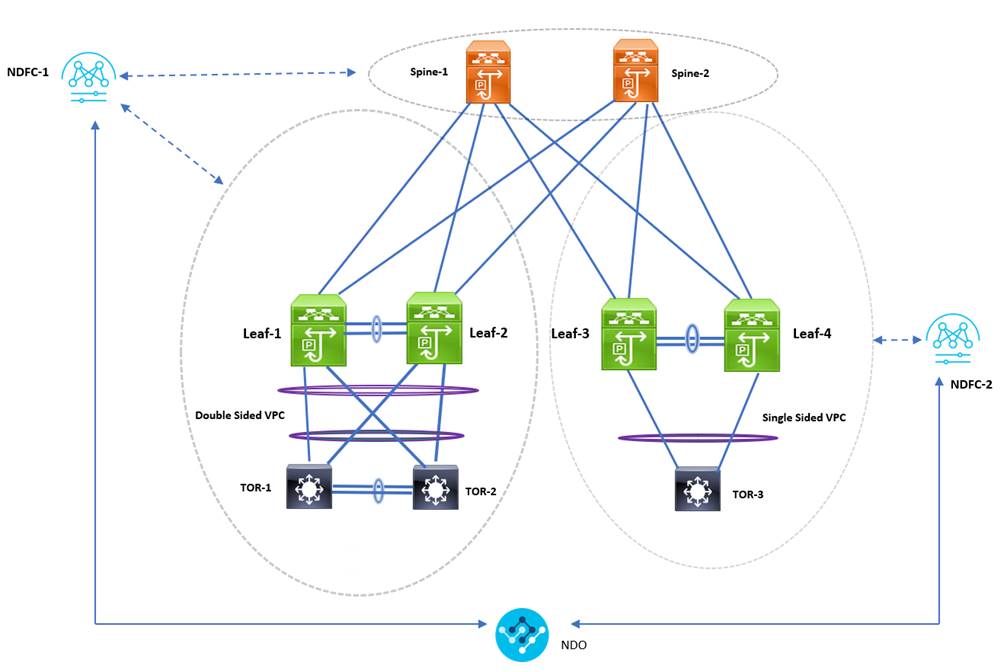
TOR switches provide L2 connectivity to the end hosts. For extending Layer2, TOR should be configured with VLANs, trunks, and Port-channels. This can be achieved using NDFC and NDO. We have taken an example design in the below network diagram.
Design Considerations
The leaf switches and the TOR nodes can be connected either using Single-sided vPC or Double-sided vPC. vPC Peering between the Leaf switches can be either physical peering or Virtual Peering, whereas vPC peering between the TOR nodes is always physical peering. The following sections describe two types of Leaf-TOR topologies – Single-sided and Double-sided vPC.
vPC with Spanning Tree Deployment in NDFC
With TOR switches being at layer 2, user must be cautious about spanning tree protocol configuration. Any misconfiguration could lead to layer 2 loop, which in turn may bring down the entire host connectivity network. Hence having stable and redundant loop free layer 2 network connectivity is necessary while connecting TORs to the leaf layer.
vPC supports RSTP, MSTP and PVST+ layer2 loop free protocols. Customer can choose Spanning-tree protocol according to their need. Please refer reference section at the bottom of the document for spanning-tree scalability support. Similar Spanning-tree protocol should be used on Leaves and TORs. Spanning-tree root should always be on the Leaf switches. For this document MST is used as the Spanning-tree protocol on Leaf and TOR switches.
While configuring MSTP, MSTP Bridge Priority must be the same for vPC nodes. It is recommended to make the Leaf Nodes as the Root Bridge. Out of 2 leaf nodes, One Leaf will act as the Root Bridge. For RSTP it is not mandatory to have them same bridge priority.
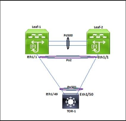
Single-sided vPC
In this topology, Leaf nodes form a vPC Pair and have a Port-Channel connecting to TOR as a member link.
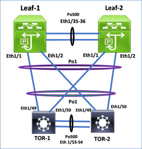
Double-sided vPC between Leaf and TOR nodes
In this topology, Leaf and TOR nodes are configured with Physical vPC peer link making it a double-sided vPC.
Fabric and vPC configuration using NDFC:
Configuring VXLAN Fabric
To create an EVPN VXLAN fabric, perform the following steps:
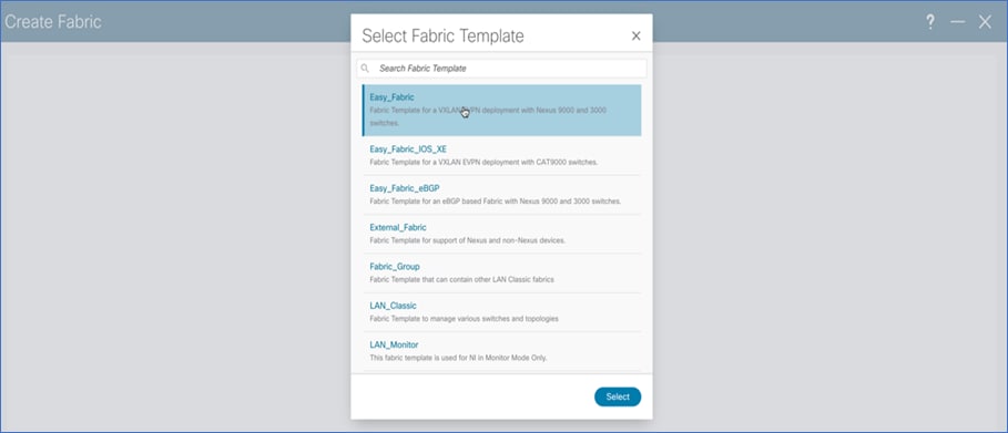
Step 1. Create Fabric.
To create fabric, choose Easy_Fabric template. This template is used for VXLAN EVPN fabric deployment. Fabric parameters like BGP ASN, underlay properties, replication mode, etc. must be provided while configuring the fabric.
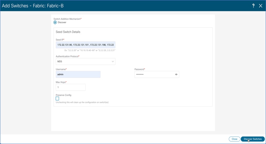
Step 2. Discover Switches.
Use seed IP address to discover the switches. Uncheck preserve config to clear switch configuration and reload the devices. Max hop count allows the discovery of connected switches by the number of hops.
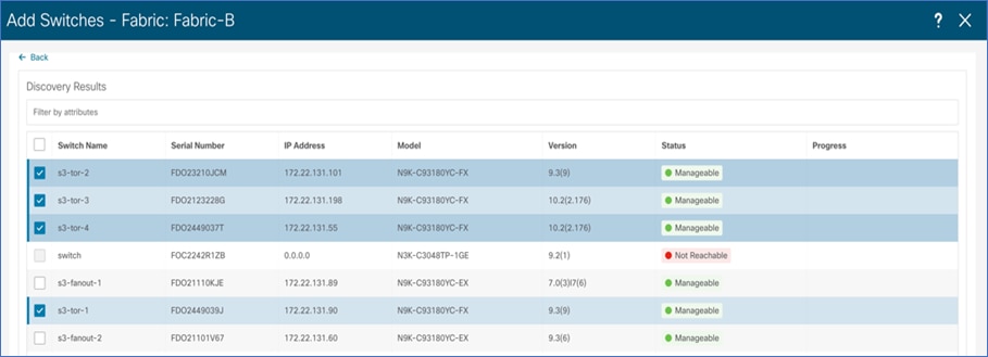
Step 3. After the switches are discovered, add these switches to the Fabric.
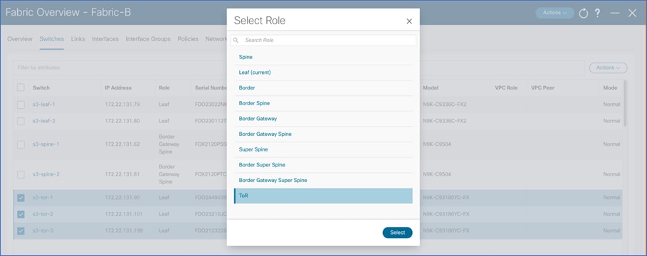
Step 4. Change device role and click Deploy All to generate and push configuration to the devices.
After the devices are added, by default they will be assigned a default role depending on the platform. After assigning Spine and Leaf roles, select the devices that are used as TOR. Change the role to TOR. This will push TOR-relevant configuration to the respective devices.
Configuring Double-sided vPC
To form a double-sided vPC, two vPC domains need to be configured, one between Leaf switches and another one between the TORs. To configure double-sided vPC using the NDFC Web UI, perform the following steps:
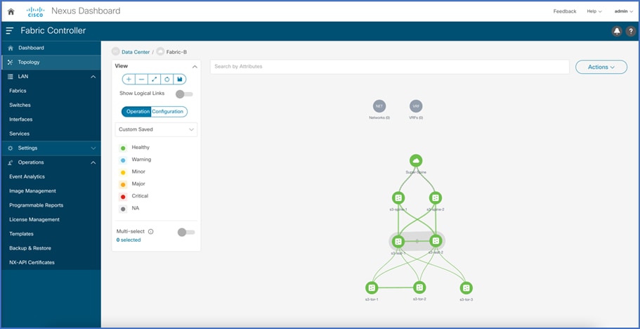
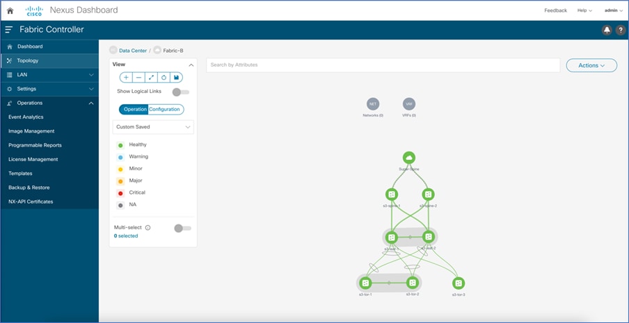
Step 1. Click Topology to configure vPC.
After the devices are added to the fabric according to role, navigate to the Topology tab to display the overall view.

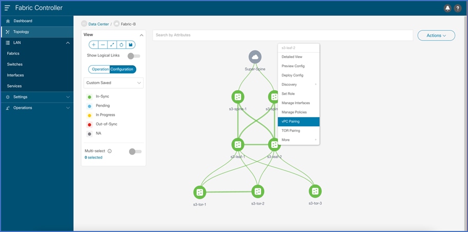
Step 2. Configure vPC between Leafs.
To configure Leaf-1 and Leaf-2 as vPC1 Peers, click on one of the leaf switches and select vPC Peering

Select the peer switch to form vPC. If there is no direct physical connectivity between the Leaf switches, Fabric peering can be configured by enabling a Virtual peer link.

vPC Pairing is formed between leaf-1 and leaf-2.
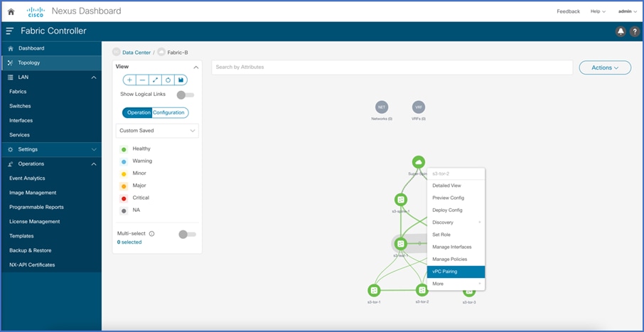
Step 3. Configure vPC between TORs.
To configure TOR-1 and TOR-2 as vPC2 Peers, click on one of the TOR switches and select vPC Peering
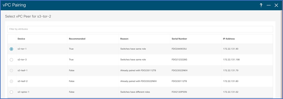
Select the peer switch to form vPC. This forms physical vPC peering between the TOR devices.
Note: Fabric peering between TOR devices is not allowed.
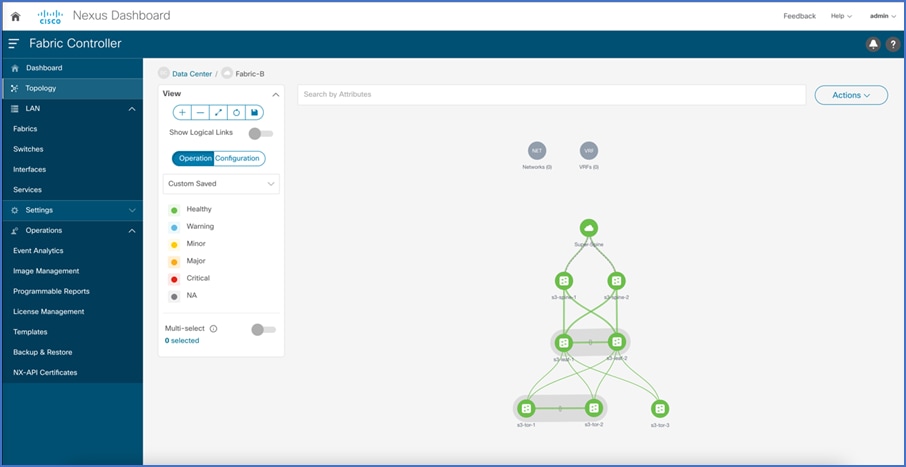
vPC Pair is formed between TOR-1 and TOR-2.
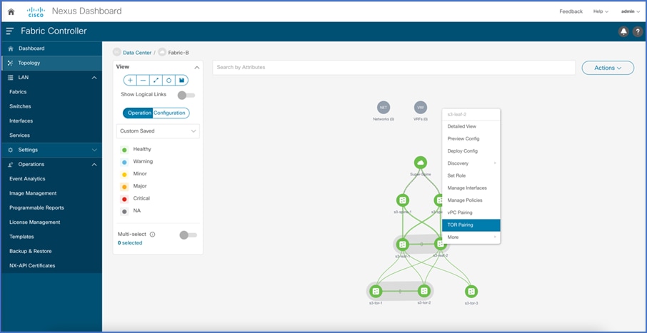
Step 4. Configure Peering between Leafs and TORs.
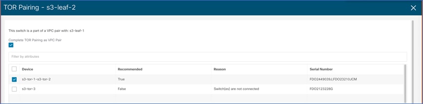
To configure Leaf-TOR peering, click on Leaf Pair and select TOR pairing. This configures port-channels on the leaf and TOR switches. It also configures these port-channels as member links of the double-sided vPC.
Select TOR pair from the list of devices to form a double-sided vPC. If there are multiple TOR pairs available, select all.
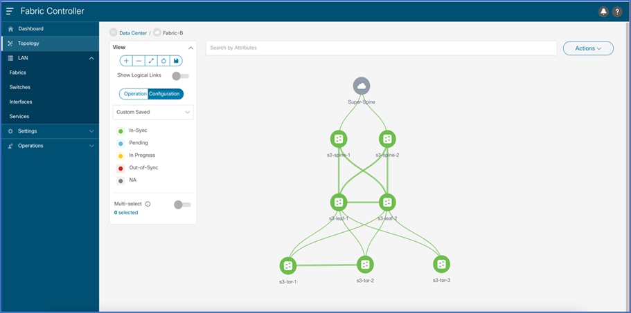
The topology view after double-sided vPC is configured.
Configuring Single-sided vPC
To configure single-sided vPC using the NDFC Web UI, perform the following steps:
Step 1. Click Topology to configure vPC.
After the devices are added to the fabric according to the role, navigate to Topology tab to display the overall view.
Step 2. Configure vPC between leaf switches.
To configure Leaf-1 and Leaf-2 as vPC1 Peers, click one of the leaf switches and select vPC Pairing.
Select the peer switch to form vPC. If there is no direct physical connectivity between the leaf switches, then Fabric peering can be configured by enabling virtual peer link.
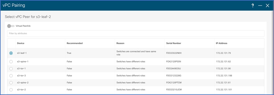
vPC Pairing is formed between leaf-1 and leaf-2.

Step 3. Configure peering between leafs and TOR.
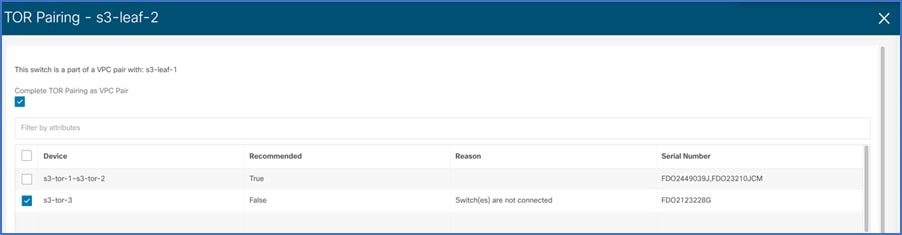
To configure TOR pairing between vPC1 and TOR-3 to form a single-sided vPC, navigate to the leaf pair and select TOR pairing. This configures the port channel on leaf switches and TOR-3. Port-channel interfaces on leaf switches are added as vPC member links.

Select the TOR device with which single-sided vPC must be configured. Multiple TOR devices can be selected to enhance further scaling.
Configuring MSTP
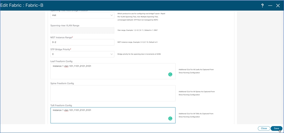
On NDFC Web UI, choose Fabrics > Edit Fabric > Advanced tab. Enter the Spanning-tree Root Bridge Protocol details. Choose MST from the drop-down list. By default, only MST instance 0 will be configured.
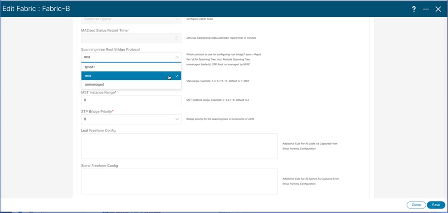
If multiple instances of MSTP must be configured, then fill in the instance range. In the freeform template field, add the instance to VLAN mappings.
Overlay Configuration using Orchestrator Service
For multi-site fabric configuration, Nexus Dashboard Orchestrator is used as a central controller to maintain consistency across sites with respect to VLAN, VRF, and network configuration. To configure overlay using Nexus Dashboard Orchestrator Web UI, perform the following steps:
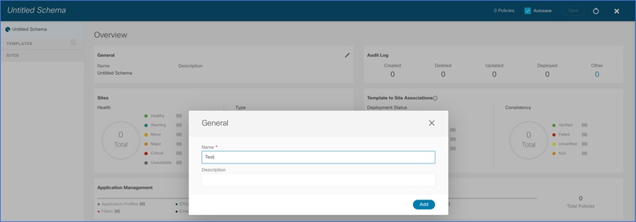
Step 1. On the Nexus Dashboard Orchestrator Web UI, create Schema.
Before creating VRF and Networks, a schema must be created. Schema acts as a collection of templates used to define policies. While designing schemas, supported scalability limits for the number of schemas, templates, and objects per schema must be considered. On Nexus Dashboard Orchestrator Web UI, choose Application Management > Schemas > Add Schema.
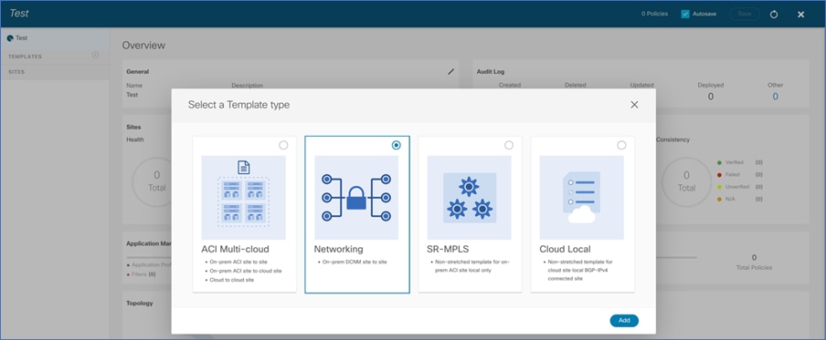
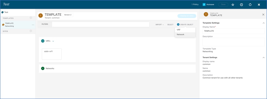
Step 2. Create Template.
A template is a collection of objects like VRFs, Networks, and so on. A template represents the atomic unit of change for objects. Any changes applied to a template are always pushed immediately to all the site(s) mapped to the template. From Nexus Dashboard Orchestrator Web UI, navigate to the schema created in the previous step and add a template. Use Networking template for creating VRF and Networks.
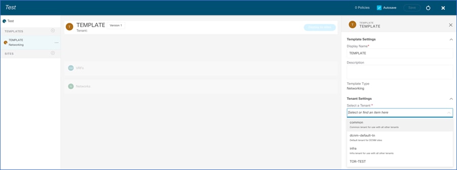
While creating a template, choose the appropriate tenant. For NDFC, dcnm-default is the only supported template.
Step 3. Create VRF.
In the template page, create vrf object, by providing vrf name.
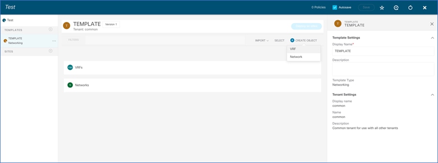
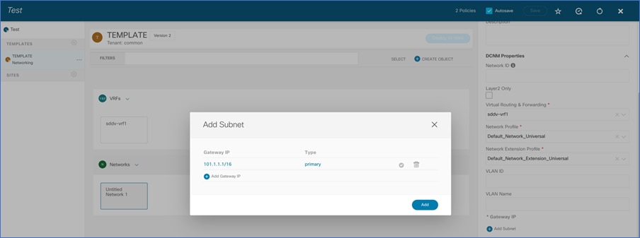
Step 4. Create Network.
In the template page, create network object, by adding Network Name, gateway address and associated vrf.
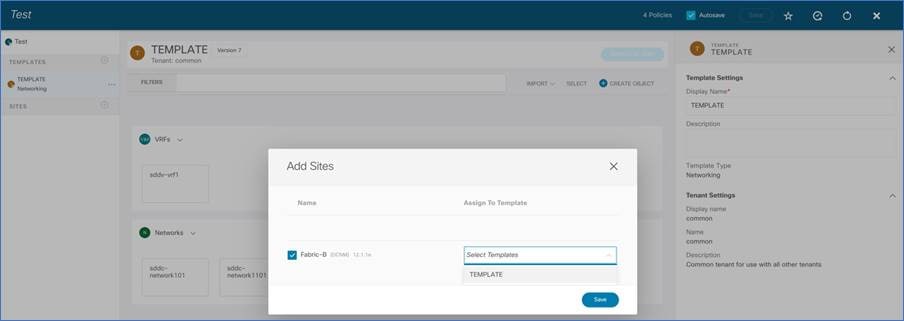
Step 5. Associate sites.
Before VRF and Network configurations is pushed to the TORs, sites must be associated with the template. Navigate to the template and add sites. Select the fabrics to which VRF/Network configuration must be pushed.
Step 6. Push VRF, VLAN, and Network configurations from Nexus Dashboard Orchestrator to the sites.
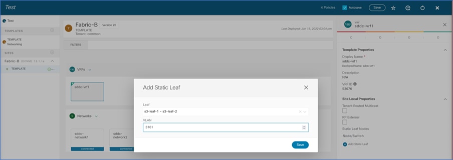
In the previous steps, the template is created and associated with the sites. Also, VRF and Network objects are created as part of the template. In this step, VRF, VLAN, and Network configurations is associated with the switch ports and this configuration is deployed to devices. Navigate to Schema> Sites > Template, select the VRF to be deployed
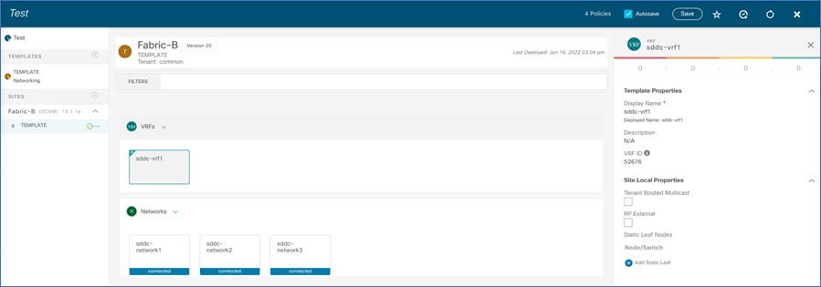
Select the leaf pair and spine, and add the forwarding vlan for the selected VRF. This creates an SVI on leaf and spine for forwarding Layer-3 traffic.
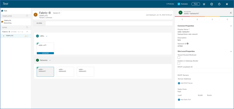
Select the network to be deployed.
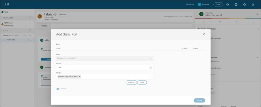
Select leaf pairs, and associate vlan and vPC/interface from TOR to the end host. Here vlan 101 is part of VRF sddc-vrf1 and used for host connectivity. This step creates VLAN 101 on TORs and Leaves switches and also allows it on Host ports (Ports on TOR connected to host) and the Trunk ports connecting Leafs and TOR switches. For scaled network, multiple TOR interfaces can also be configured.
Appendix
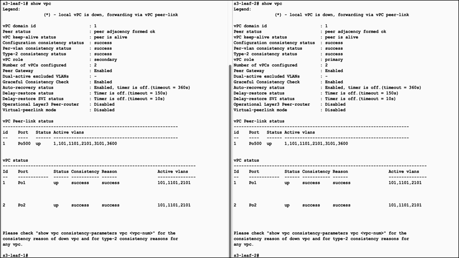
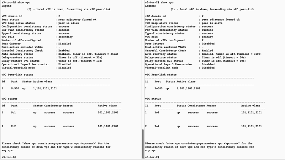
Verifying vPC from Leaf toward TOR Switch
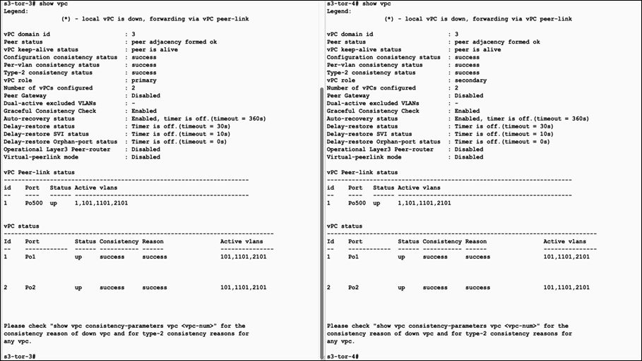
Verifying vPC from TOR toward Leaf Switch
Verifying Spanning Tree Configuration
In this sample configuration, MSTP is enabled on all four switches. Both the vPC leaf nodes are configured with same Bridge priority. Both leaf1 and leaf 2 act as root bridge for TOR1 and TOR2.
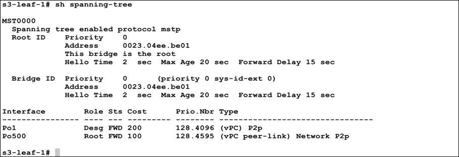
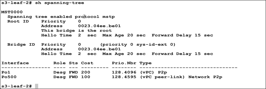
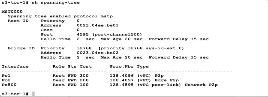
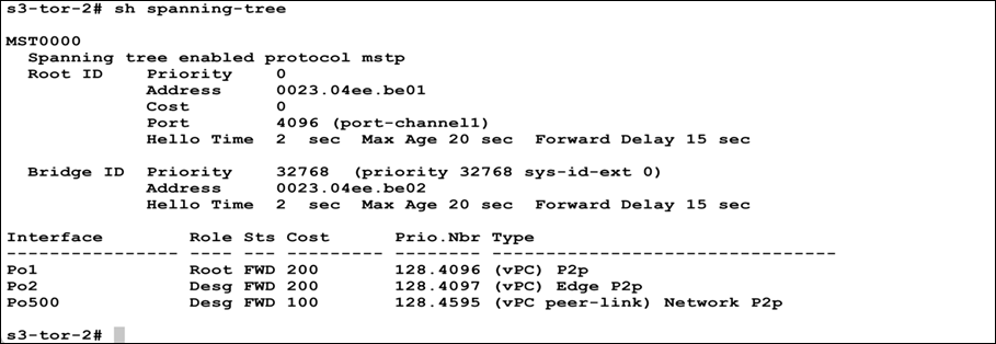
Note: Po2 is the port channel connecting to the end hosts/servers.
Additional References
Spanning Tree Scalability Guide
VXLAN Multisite Design Guide:
NDFC Deployment Guide
Legal Information
Cisco and the Cisco logo are trademarks or registered trademarks of Cisco and/or its affiliates in the U.S. and other countries. To view a list of Cisco trademarks, go to this URL: www.cisco.com/go/trademarks. Third-party trademarks mentioned are the property of their respective owners. The use of the word partner does not imply a partnership relationship between Cisco and any other company. (1110R)
Any Internet Protocol (IP) addresses and phone numbers used in this document are not intended to be actual addresses and phone numbers. Any examples, command display output, network topology diagrams, and other figures included in the document are shown for illustrative purposes only. Any use of actual IP addresses or phone numbers in illustrative content is unintentional and coincidental.
© 2023 Cisco Systems, Inc. All rights reserved.