Overview

Overview

Cisco Nexus Dashboard provides a common platform for deploying Cisco Data Center applications. These applications provide real time analytics, visibility and assurance for policy and infrastructure.

The Cisco Nexus Dashboard server is required for installing and hosting the Cisco Nexus Dashboard application.

The appliance is orderable in the following versions:

  • ND-NODE-G5S: Single-node appliance

  • ND-CLUSTERG5S: Three-node version that leverages the same configuration as ND-NODE-G5S but with three appliances included

Components

The ND-NODE-G5S appliance is configured with the following components:

  • CIMC-LATEST-D: IMC SW (Recommended) latest release for C-Series Servers

  • ND-CPU-A9454P: ND AMD 9454P 2.75GHz 290W 48C/256MB Cache DDR5 4800MT/s

  • ND-M2-240G-D: ND 240GB M.2 SATA Micron G2 SSD

  • ND-M2-HWRAID-D: ND Cisco Boot optimized M.2 Raid controller

  • ND-TPM2-002D-D: ND TPM 2.0 FIPS 140-2 MSW2022 compliant AMD M8 servers

  • ND-RIS1A-225M8: ND C225 M8 1U Riser 1A PCIe Gen4 x16 HH

  • ND-HD24TB10KJ4-D: ND 2.4TB 12G SAS 10K RPM SFF HDD (4Kn)

  • ND-SD960GBM3XEPD: ND 960GB 2.5in Enter Perf 6G SATA Micron G2 SSD (3X)

  • Power supplies:

    • 1200W AC Titanium Power Supply for C-series Rack Servers

    • 1050W -48V DC Power Supply for UCS Rack Server

    • 1050W -48V DC Power Supply for APIC servers (India)

  • ND-MRX32G1RE3: ND 32GB DDR5-5600 RDIMM 1Rx4 (16Gb)

  • ND-RAID-M1L16: ND 24G Tri-Mode M1 RAID Controller w/4GB FBWC 16Drv

  • ND-O-ID10GC-D: Intel X710T2LOCPV3G1L 2x10GbE RJ45 OCP3.0 NIC

  • ND-OCP3-KIT-D: C2XX OCP 3.0 Interposer W/Mech Assy

  • ND-P-V5Q50G-D: Cisco VIC 15425 4x 10/25/50G PCIe C-Series w/Secure Boot

External Features

ND-NODE-G5S Front Panel Features

The following figure shows the front panel features of the small form-factor drive versions of the server.

For definitions of LED states, see Front-Panel LEDs.

Figure 1. ND-NODE-G5S Front Panel

1

Drive bays 1 – 10 support SAS/SATA hard disk drives (HDDs) and solid state drives (SSDs).

2

Unit identification button/LED

3

Power button/power status LED

4

KVM connector (used with KVM cable that provides one DB-15 VGA, one DB-9 serial, and two USB 2.0 connectors)

5

System LED cluster:

  • Fan status LED

  • System Status LED

  • Power supply status LED

  • Network link activity LED

  • Temperature status LED

-

ND-NODE-G5S Rear Panel Features

The rear panel features can be different depending on the number and type of PCIe cards in the server.

The following figure shows the rear panel features of the server with three riser configuration.

For definitions of LED states, see Rear-Panel LEDs.

Figure 2. ND-NODE-G5S Rear Panel Three-Riser Configuration

1

PCIe slots

Following PCIe Riser combinations are available for 3 HH Riser cage configuration:

  • Riser 1:

    • Riser 1A (PCIe Gen4): Half-height, 3/4 length, x16, NCSI, Single Wide GPU.

2

Power supply units (PSUs), two, which can be redundant when configured in 1+1 power mode.

3

Modular LAN-on-motherboard (mLOM) card bay (x16 PCIe lane)

4

System identification button/LED

5

USB 3.0 ports (two)

6

Dedicated 1 GB Ethernet management port

7

COM port (RJ-45 connector)

8

VGA video port (DB-15 connector)

Component Location

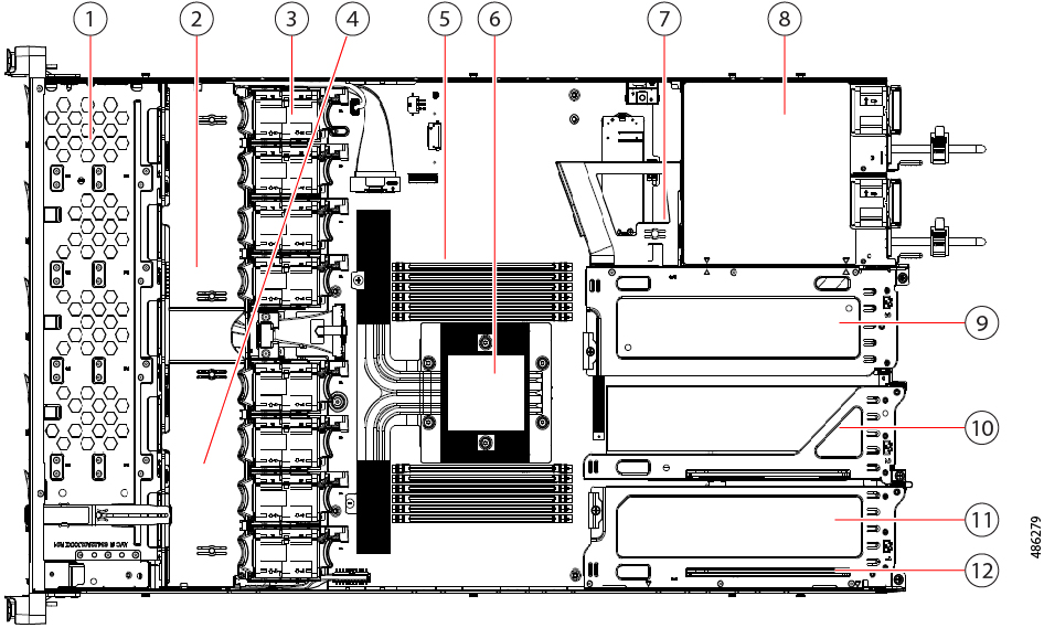
This topic shows the locations of the field-replaceable components and service-related items. The view in the following figure shows the server with the top cover removed.

Figure 3. ND-NODE-G5S Three Riser Configuration Serviceable Component Locations

1

Front-loading drive bays 1–10

2

Cisco M8 24G SAS RAID card or Cisco M8 24G SAS HBA Controller

3

Cooling fan modules, eight.

Each fan is hot-swappable.

4

SuperCap module mounting bracket

The SuperCap module (not shown) that mounts into this location provides RAID write-cache backup.

5

DIMM sockets on motherboard, 12 total.

6

Motherboard CPU socket

7

M.2 module connector

Supports a boot-optimized RAID controller with connectors for up to two SATA M.2 SSDs

8

Power Supply Units (PSUs), two

9

PCIe riser slot 3

10

PCIe riser slot 2

11

PCIe riser slot 1

12

Modular LOM (mLOM) card bay on chassis floor (x16 PCIe lane)

Summary of Server Features

The following table lists a summary of server features for the ND-NODE-G5S.

Feature

Description

Chassis

One rack-unit (1RU) chassis.

Central Processor

One socket, 4th Gen AMD EPYC™ processors, with up to 128 cores.

Memory

Up to 12 DIMM slots per CPU, supports DDR5 memory with speeds up to 4800 MT/s, maximum memory capacity of 3 TB using 256 GB DIMMs.

Multi-bit error protection

Multi-bit error protection is supported.

Video

The Cisco Integrated Management Controller (CIMC) provides video using the Matrox G200e video/graphics controller:

  • Integrated 2D graphics core with hardware acceleration.

  • Embedded DDR memory interface supports up to 512 MB of addressable memory (8 MB is allocated by default to video memory).

  • Supports display resolutions up to 1920 x 1200 16bpp @ 60Hz.

  • High-speed integrated 24-bit RAMDAC.

  • Single lane PCI-Express host interface running at Gen 1 speed.

Baseboard management

BMC, running Cisco Integrated Management Controller (Cisco IMC) firmware. Depending on your Cisco IMC settings, Cisco IMC can be accessed through the 1-Gb dedicated management port or a Cisco virtual interface card.

Network and management I/O

Rear panel:

  • One 1-Gb Ethernet dedicated management port (RJ-45 connector).

  • One RS-232 serial port (RJ-45 connector).

  • One VGA video connector port (DB-15 connector).

  • Two USB 3.0 ports.

  • One flexible modular LAN on motherboard (mLOM)/OCP 3.0 slot that can accommodate various interface cards.

Front panel:

  • One KVM console connector (supplies two USB 2.0 connectors, one VGA DB15 video connector, and one serial port (RS232) RJ45 connector).

Modular LAN on Motherboard (mLOM)/ OCP3 3.0 slot

The Cisco VIC 15425 4x 10/25/50G PCIe C-Series card is installed in the dedicated mLOM/OCP 3.0 slot on the motherboard.

Power

Up to two of the following hot-swappable power supplies:

  • 1050 W DC.

  • 1200 W (AC).

  • 1600 W (AC).

  • 2300 W (AC).

One power supply is mandatory; one more can be added for 1 + 1 redundancy.

ACPI

The advanced configuration and power interface (ACPI) 4.0 standard is supported.

Front Panel

The front panel controller provides status indications and control buttons.

Cooling

Eight hot-swappable fan modules for front-to-rear cooling.

InfiniBand

The PCIe bus slots in this server support the InfiniBand architecture.

Expansion Slots

The server is onboarded with the following configuration of the expansion slot:

  • Riser 1: One x16 PCIe Gen4/Gen5 Slot, half-height.

Status LEDs and Buttons

This section contains information for interpreting front, rear, and internal LED states.

Front-Panel LEDs

Figure 4. Front Panel LEDs
Table 1. Front Panel LEDs, Definition of States

LED Name

States

1

Power button/LED ()

  • Off—There is no AC power to the server.

  • Amber—The server is in standby power mode. Power is supplied only to the Cisco IMC and some motherboard functions.

  • Green—The server is in main power mode. Power is supplied to all server components.

2

Unit identification (

  • Off—The unit identification function is not in use.

  • Blue, blinking—The unit identification function is activated.

3

System health ()

  • Green—The server is running in normal operating condition.

  • Green, blinking—The server is performing system initialization and memory check.

  • Amber, steady—The server is in a degraded operational state (minor fault). For example:

    • Power supply redundancy is lost.

    • CPUs are mismatched.

    • At least one CPU is faulty.

    • At least one DIMM is faulty.

    • At least one drive in a RAID configuration failed.

  • Amber, 2 blinks—There is a major fault with the system board.

  • Amber, 3 blinks—There is a major fault with the memory DIMMs.

  • Amber, 4 blinks—There is a major fault with the CPUs.

4

Power supply status ()

  • Green—All power supplies are operating normally.

  • Amber, steady—One or more power supplies are in a degraded operational state.

  • Amber, blinking—One or more power supplies are in a critical fault state.

5

Fan status ()

  • Green—All fan modules are operating properly.

  • Amber, blinking—One or more fan modules breached the non-recoverable threshold.

6

Network link activity ()

  • Off—The Ethernet LOM port link is idle.

  • Green—One or more Ethernet LOM ports are link-active, but there is no activity.

  • Green, blinking—One or more Ethernet LOM ports are link-active, with activity.

7

Temperature status ()

  • Green—The server is operating at normal temperature.

  • Amber, steady—One or more temperature sensors breached the critical threshold.

  • Amber, blinking—One or more temperature sensors breached the non-recoverable threshold.

Rear-Panel LEDs

Figure 5. Rear Panel LEDs
Table 2. Rear Panel LEDs, Definition of States

LED Name

States

1

Rear unit identification

  • Off—The unit identification function is not in use.

  • Blue, blinking—The unit identification function is activated.

2

1-Gb Ethernet dedicated management link speed

  • Off—Link speed is 10 Mbps.

  • Amber—Link speed is 100 Mbps.

  • Green—Link speed is 1 Gbps.

3

1-Gb Ethernet dedicated management link status

  • Off—No link is present.

  • Green—Link is active.

  • Green, blinking—Traffic is present on the active link.

4

Power supply status (one LED each power supply unit)

AC power supplies:

  • Off—No AC input (12 V main power off, 12 V standby power off).

  • Green, blinking—12 V main power off; 12 V standby power on.

  • Green, solid—12 V main power on; 12 V standby power on.

  • Amber, blinking—Warning threshold detected but 12 V main power on.

  • Amber, solid—Critical error detected; 12 V main power off (for example, over-current, over-voltage, or over-temperature failure).

DC power supplies:

  • Off—No DC input (12 V main power off, 12 V standby power off).

  • Green, blinking—12 V main power off; 12 V standby power on.

  • Green, solid—12 V main power on; 12 V standby power on.

  • Amber, blinking—Warning threshold detected but 12 V main power on.

  • Amber, solid—Critical error detected; 12 V main power off (for example, over-current, over-voltage, or over-temperature failure).

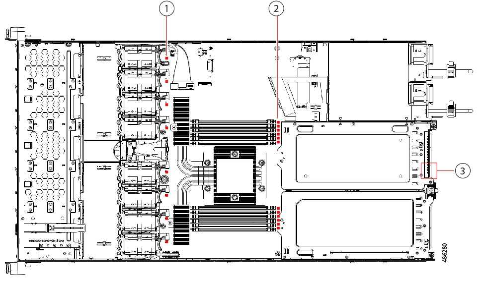
Internal Diagnostic LEDs

The server has internal fault LEDs for CPUs, DIMMs, and fan modules.

Figure 6. Internal Diagnostic LED Locations

1

Fan module fault LEDs (one behind each fan connector on the motherboard)

  • Amber—Fan has a fault or is not fully seated.

  • Green—Fan is OK.

2

DIMM fault LEDs (one behind each DIMM socket on the motherboard)

These LEDs operate only when the server is in standby power mode.

  • Amber—DIMM has a fault.

  • Off—DIMM is OK.

3

CPU fault LEDs (beside rear USB2 connector).

These LEDs operate only when the server is in standby power mode.

  • Amber—CPU has a fault.

  • Off—CPU is OK.

-