
New and changed information
The following table provides an overview of the significant changes up to this current release. The table does not provide an exhaustive list of all changes or of the new features up to this release.
| Release Version | Feature | Description |
|---|---|---|
|
Nexus Dashboard 4.1.1 |
Improved security and segmentation navigation and workflow. |
Beginning with Nexus Dashboard 4.1.1, the navigation and workflow for security and segmentation features in Nexus Dashboard Enhanced Classic LAN fabrics have been enhanced. |
Manage segmentation and security
Beginning with Nexus Dashboard release 4.1.1, the navigation and workflow for segmentation and security features in Nexus Dashboard Enhanced Classic LAN fabrics have been enhanced.
To view, edit, or create segmentation and security configurations for a Enhanced Classic LAN fabric:
-
Navigate to the main Fabrics window.
Manage > Fabrics
-
Locate the Enhanced Classic LAN fabric where you want to work with segmentation and security.
-
Single-click the appropriate Enhanced Classic LAN fabric.
The Summary window for that Enhanced Classic LAN fabric appears, with the Overview tab selected by default.
-
Click the Segmentation and security tab.
-
Determine the area in segmentation and security where you want to work.
View and manage certificates used by Nexus Dashboard
You can view and manage certificates used by Nexus Dashboard through the Security page.
To access the Security window, navigate to Admin > Users and Security > Security. Use these tabs to configure security in this window:
Security configuration
The Security configuration page allows you to configure authentication session timeouts and security certificates used by your Nexus Dashboard cluster.
-
You must have the keys and certificates you plan to use with Nexus Dashboard already generated.
Typically, this includes the following files:
-
Private key (
nd.key) -
Certificate Authority’s (CA) public certificate (
ca.crt) -
CA-signed certificate (
nd.crt)
Generating these files for self-signed certificates is described in the section "Generating a private key and self-signed certificate" in the Managing Certificates in your Nexus Dashboard.
-
-
We recommend creating a configuration backup of your Nexus Dashboard cluster before making changes to the security configurations.
For more information about backups, see "Backup and Restore" in Backing Up and Restoring Your Nexus Dashboard.
To edit security configuration:
-
Edit security configuration.
-
From the main navigation menu, choose Admin > Users and Security.
-
Click the Security tab.
-
In the main pane, click the Security configuration tab.
-
In the main pane, click the Edit icon.
-
-
In the Edit security configuration screen that opens, update one or more fields as required:
Note that uploading the keys and certificate files is not supported and you will need to paste the information in the following fields.
-
Update the Session timeout.
This field defines the duration of the API tokens with the default duration set to 20 minutes.
-
In the Domain name field, provide your domain.
-
Check the box in the Minimum TSL version: TLSV1.3 field if you want to set the minimum SSL version to TLSV1.3.
The minimum SSL version is set to TLSV1.2 by default. Checking this box to set the minimum version to TLSV1.3 will reject all clients using a TLSV1.2 connection request.
-
To disable Qualtrics integration from the browser at a system wide level, check the box in the Enforce strict content security policy field.
-
Click the SSL Ciphers field and choose any additional cipher suites you want to enable from the drop-down list or click the x icon on an existing cipher suite to remove it.
Cipher suites define algorithms (such as key exchange, bulk encryption, and message authentication code) used to secure a network connection. This field allows you to customize which cipher suites your Nexus Dashboard cluster will use for network communication and disable any undesired suites, such as the less secure TLS1.2 and TLS1.3.
-
In the Key field, provide your private key.
-
In the RSA Certificate field, provide the CA-signed or self-signed certificate.
-
In the Root Certificate field, provide the CA’s public certificate.
-
(Optional) If your CA provided an Intermediate Certificate, provide it in the Intermediate Certificate field.
-
Click Save to save the changes.
After you save your changes, the GUI will reload using the new settings.
-
Violation action
The Violation action window shows the number of unsuccessful attempted login actions.
To edit the information that is provided in the Violation action window:
-
From the main navigation menu, choose Admin > Users and Security.
-
Click the Security tab.
-
In the main pane, click the Violation action tab.
Information on unsuccessful attempted login actions is displayed.
-
Click Edit.
The Login attempt action window appears.
-
Edit the Login attempt action settings, if necessary.
-
In the Maximum login attempts field, set the maximum number of login attempts until the maximum action is triggered.
The default entry is 0.
-
In the Maximum password length field, set the maximum password length.
The default entry is 8.
-
In the Maximum login attempted action field, choose the action that will take place when the number of maximum login attempts has been surpassed.
-
In the Block for field, set the amount of time, in seconds, minutes, or hours, that a login block will take place when the number of maximum login attempts has been surpassed.
-
In the Block admin for field, set the amount of time, in seconds, minutes, or hours, that an admin login block will take place when the number of maximum login attempts has been surpassed.
-
-
-
Click Save.
Security domains
A restricted security domain allows an administrator to prevent a group of users from viewing or modifying any objects created by a group of users in a different security domain, even when users in both groups have the same assigned privileges.
For example, an administrator in restricted security domain (domain1) will not be able to see fabrics, services, cluster or user configurations in another security domain (domain2).
Note that a user will always have read-only visibility to system-created configurations for which the user has proper privileges. A user in a restricted security domain can be given a broad level of privileges within that domain without the concern that the user could inadvertently affect another group’s physical environment.
To create a security domain:
-
Create a new security domain.
-
From the main navigation menu, choose Admin > Users and Security.
-
Click the Security tab.
-
In the main pane, click the Security domains tab.
-
In the main pane, click Create security domain.
-
-
In the Create security domain screen that opens, provide the domain details.
-
Provide the Name for the domain.
-
(Optional) Provide a description for the domain.
-
Click Save to save the domain.
-
JWT keys
To create a JWT key:
-
From the main navigation menu, choose Admin > Users and Security.
-
Click the Security tab.
-
In the main pane, click the JWT keys tab.
-
Click Create JWT key.
The Create JWT key window appears.
-
Enter a service name for the JWT key in the Service name field.
-
Enter a JWT API key in the JWT API key field.
-
Enter a JWT public key in the JWT public key field.
-
Enter the remote ID claim information in the Remote ID claim field.
-
Click Create.
Credentials store
You can add an external Credentials store that allows you to store and retrieve network credentials from an external vault, such as the CyberArk vault, instead of a local storage system.
To add a credentials store:
-
From the main navigation menu, choose Admin > Users and Security.
-
Click the Security tab.
-
In the main pane, click the Credentials store tab.
-
Click Add credential store.
The Edit credential store page appears.
-
In the Store type field, choose a store type, such as CyberArk.
-
Enter the necessary information in the remaining fields, depending on the choice that you made in the Store type field.
For example, if you chose CyberArk in the Store type field, make the necessary choices in the following fields:
-
In the CyberArk CCP URL field, enter the CyberArk Central Credential Provider (CCP) URL.
For more information, see Central Credential Provider (CCP).
-
In the Certificate name field, choose the appropriate certificate from the dropdown list.
The Certificate name field lists the certificates that you configured in Admin > Certificate Management.

Ensure that the system certificate you configured is mapped to the CyberArk feature to use the certificate name here.
For more information on system certificates, see Managing Certificates in your Nexus Dashboard.
-
-
Click Resync/Save.
Validating peer certificates
You can import a fabric controller’s Certificate Authority (CA) root certificate chain into Nexus Dashboard. This allows you to verify that the certificates of hosts to which your Nexus Dashboard connects (such as fabric controllers) are valid and are signed by a trusted Certificate Authority (CA) when you add the fabrics.
Exporting a certificate chain from Cisco APIC
-
Log in to your Cisco APIC.
-
Check which key ring is being used for management access:
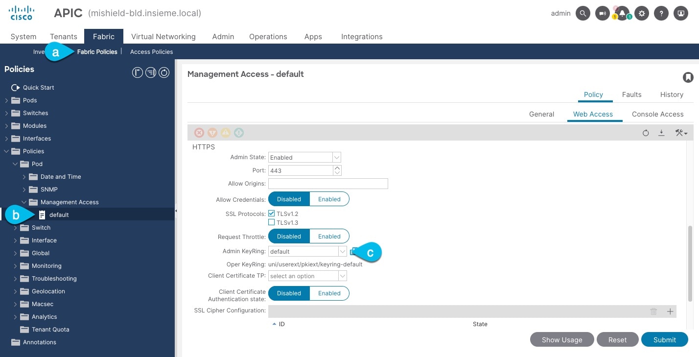
-
In the top navigation bar, choose Fabric > Fabric Policies.
-
In the left navigation menu, choose Policies > Pod> Management Access.
-
In the main pane, note the name in the Admin KeyRing field.
In the above example, the
defaultkey ring is being used. However, if you created a custom key ring with a custom certificate chain, the name of that key ring would be listed in the Admin KeyRing field.Custom security configuration for Cisco APIC is described in detail in Cisco APIC Security Configuration Guide for your release.
-
-
Export the certificate used by the key ring:
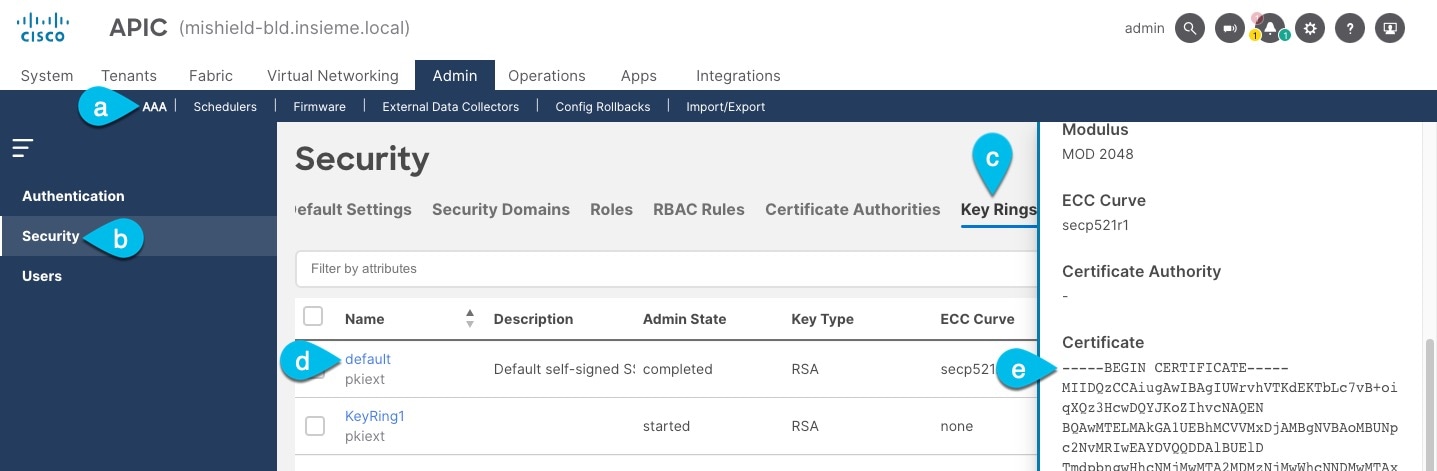
-
In the top navigation bar, choose Admin > AAA.
-
In the left navigation menu, choose Security.
-
In the main pane, choose the Key Rings tab.
-
Click the name of the key ring you found in the previous step and copy the Certificate.
The above example shows the
defaultkey ring from the previous step. However, if you had a custom key ring configured, choose the CA certificate chain used to create the key ring.You must include the
-----BEGIN CERTIFICATE-----and-----END CERTIFICATE-----in the text you copy, for example:-----BEGIN CERTIFICATE----- MIIDQzCCAiugAwIBAgIUWrvhVTKdEKTbLc7vB+oiqXQz3HcwDQYJKoZIhvcNAQEN [...] -----END CERTIFICATE-----
-
Importing certificates into Nexus Dashboard
-
Log in to your Nexus Dashboard where you plan to onboard the fabrics.
-
Import the certificate into Nexus Dashboard.
-
Log in to your Nexus Dashboard where you will onboard the fabrics.
-
From the main navigation menu, choose Admin > Certificate Management.
-
Click the CA Certificates tab.
-
Click Add CA certificate, provide a unique name for the certificate, and paste the certificate chain you copied from your fabric’s controller.
-
-
Proceed with adding the fabric as you typically would, but enable the Verify Peer Certificate option.
Note that if you enable the Verify Peer Certificate option but don’t import the valid certificate, fabric onboarding will fail.
Adding fabrics is described in Creating LAN and ACI Fabrics and Fabric Groups.
Working with VRFs
Use the VRFs tab to create, edit, delete, attach, detach, import, export, and deploy configurations for VRFs. You can create networks only after creating a VRF except except when creating Layer 2 only networks.
-
In the Segmentation and security area, click the VRFs subtab.
-
Review the information in the VRFs window.
The VRFs window shows information on already-configured VRFs.
View VRF information
-
Review the information provided in the VRFs window.
-
The Config-Sync Status area above the table provides information on the status of all of the VRF deployments in the fabric.
-
The table provides information on individual VRFs in the fabric.
VRFs Table Fields and Description Field Description VRF Name
Specifies the name of the VRF.
VRF Status
Specifies whether the status of the VRF deployment as NA, Out of Sync, Pending, Deployed, and so on.
-
-
Click the gear icon to the right of the table to change the columns in the table.
Click the toggle switch to enable or disable the column options, including these additional options:
-
Description
-
Default security tag
-
-
Click the table header to sort the entries in alphabetical order for the selected parameter.
-
Perform any of the following actions in the VRFs window.
The following table describes the action items that are available in the Actions drop-down list.
VRFs Actions and Description Action Item Description Create
Allows you to create a VRF. See Create a VRF for more information.
Edit
Allows you to edit the selected VRF.
-
To edit a VRF, choose the check box next to the VRF that you want to edit and choose Edit.
On the Edit VRF page, you can edit the parameters.
-
Click Save to retain the changes or click Close to discard the changes.
Multi-attach
Allows you to provision the VRF on multiple switches.
-
To attach a VRF, choose the check box next to the VRF that you want to attach the switches to and choose Multi-attach.
On the Multi-attach of VRFs page, you can specify the switches where you want to deploy the VRF.
-
Click Next to proceed to the next step in the wizard or click Cancel to discard the changes.
The Summary page displays with the Proceed to Full Switch Deploy (Recommended) button selected.
-
Click Save.
The Deploy Configuration page appears.
-
Click Deploy All.
The Deploy Configuration page appears with an updated status of SUCCESS, Status Description, and Progress indicator.
-
Click Close.
The attached VRF displays as DEPLOYED in the VRF Status column.
Multi-detach
Allows you to remove the VRF configuration from the selected switches.
-
To detach a VRF, choose the check box next to the VRF that you want to detach and choose Multi-detach.
On the Multi-detach of VRFs page, you can specify the switches where you want to remove the VRF configuration.
-
Choose the check box for the switch that you want to detach from the VRF.
-
Click Next.
The Summary page displays with the Proceed to Full Switch Deploy (Recommended) button selected.
-
Click Save.
The Deploy Configuration page appears with the selected switch.
-
Click Deploy All. Click Close.
Deploy
Allows you to deploy the configuration for the selected VRF.
-
To deploy a VRF configuration, choose the check box next to the VRF for which you want to deploy the configuration and choose Deploy.
On the Deploy Configuration page, you can deploy the specified VRF configuration.
-
Click Deploy or click Close to discard the changes.
Import
Allows you to import VRF information from a .csv file for the fabric.
-
To import VRF information from a .csv file, choose Import.
The Import VRFs dialog box appears.
-
Browse to the directory and select the .csv file that contains the VRF information.
-
Click OK.
The VRF information is imported and displayed on the VRFs page.
Export
Allows you to export VRF information to a .csv file. The exported .csv file will then contain information pertaining to each VRF, including the configuration details that you saved during the creation of the VRF.
To export VRF information, choose Export.
The VRF .csv file is exported to your local directory. The file name is appended with the date and time at which the file was exported.
You can use the exported .csv file for reference or use it as a template for creating new VRFs.
Delete
Allows you to delete a selected VRF. You can select multiple VRF entries and delete them at the same time.
-
To delete a VRF, choose the check box next to the VRF that you want to delete and choose Delete.
A warning message appears asking whether you want to delete the VRF(s).
-
Click Confirm to delete or click Cancel to retain the VRF.
A message appears that the selected VRFs are deleted successfully.
-
Create a VRF
-
In the VRFs window, click Create.
The Create VRF page appears.
-
On the Create VRF page, enter the required details in the mandatory fields. The available fields vary based on the fabric type.
Field Description VRF Name
Specifies a VRF name automatically or allows you to enter a name. The VRF name should not contain any white spaces or special characters except underscore (_), hyphen (-), and colon (:).
VRF Template
A default universal template is auto-populated. This is applicable for leaf switches only.
-
Enter the necessary field values or edit pre-filled fields, as required.
The tabs and their fields on the page are explained in the following sections.
-
Click Create to create the VRF or click Close to discard the VRF.
A message appears indicating that the VRF is created.
The new VRF appears on the VRFs horizontal tab. The status is shown as NA because the VRF is created but is not yet deployed. Double-click on the configured VRF to bring up the VRF Attachments information.
If you did not associate a VLAN with a VRF when you created the VRF using these instructions, you will see
NAdisplayed in the VRF Attachments for the VRF, even if a VLAN was associated with the VRF through another process (for example, if you disabled the Enable L3VNI w/o VLAN setting).
Now that the VRF is created, you can create and deploy networks on the devices in the fabric.
General Parameters
The General Parameters tab is displayed by default. The fields in this tab are described in the following table.
| Field | Description |
|---|---|
|
Routing Protocol |
Specifies the VRF-Lite Agg-Core/Edge or Collapsed Core-WAN peering protocol options. Options are:
|
|
IP Version |
Select the IP version for VRF Lite. Options are:
|
|
OSPF Process Tag |
This field becomes editable if you selected ospf in the Routing Protocol field under the General Parameters tab. The OSPF Routing Process Tag. Maximum size is 20. |
|
OSPF Area ID |
This field becomes editable in these conditions:
The OSPF Area ID in an IP address format. |
|
OSPFv3 Process Tag |
This field becomes editable if you selected ospf in the Routing Protocol field under the General Parameters tab. The OSPFv3 Routing Process Tag. Maximum size is 20. |
|
OSPFv3 Area ID |
This field becomes editable in these conditions:
The OSPFv3 Area ID in an IP address format. |
|
VRF Description |
Provide a description of the VRF, if necessary. |
|
Enable Auto Peering over SVI Between vPC Aggregations |
Choose the check box to control per VRF iBGP/OSPF peering between Aggregations. The protocol to use is based on the VRF Lite routing protocol setting that you provided in Fabric Settings. |
|
VRF Interface MTU |
Specifies the VRF interface MTU. |
Advanced
| Field | Description |
|---|---|
|
Redistribute Direct Route Map |
Specifies the redistribute direct route map name. |
|
Max BGP Paths |
Specifies the maximum number of BGP paths. The valid value is between 1 and 64. |
|
Static Route Information |
Provides the static route information for the VRF. Click Actions > Add to add static route information for the VRF. |
|
Config Static 0/0 Route |
Choose this check box to control configuration of static default route. |
|
Enable BGP Authentication |
Choose this check box to enable BGP authentication. |
|
BGP Password Key Encryption Type |
From the drop-down list, select the encryption type. |
|
BGP Neighbor Password |
Specifies the VRF-Lite BGP neighbor password. |
|
Enable OSPF Authentication |
Select the check box to enable OSPF authentication. Deselect the check box to disable it. If you enable this field, the OSPF Authentication Key ID and OSPF Authentication Key fields get enabled. |
|
OSPF Authentication Key ID |
The Key ID is populated. |
|
OSPF Authentication Key |
The OSPF authentication key must be the 3DES key from the switch.
Plain text passwords are not supported. Log in to the switch, retrieve the encrypted key and enter it in this field. Refer, Retrieving the Authentication Key section for details. |
|
Enable Netflow |
Allows you to enable netflow monitoring on the VRF-Lite sub-interface. Note that this is supported only if netflow is enabled on the fabric. |
|
Netflow Monitor |
Specifies the monitor for the VRF-Lite netflow configuration. To enable netflow on a VRF-Lite sub-interface, you must enable netflow at the VRF level and VRF extension level. Check the Enable_IFC_Netflow check box in the VRF attachment while you edit an extension to enable netflow monitoring. For more information, see the "Configuring Netflow support" section in Creating LAN and ACI Fabrics and Fabric Groups. |
|
NetFlow Sampler |
Specify the name of the Netflow sampler.
The Netflow Sampler is applicable to Cisco Nexus 7000 Series switches only. |
VRF attachments
Use this window to attach or detach attachments to or from a VRF, respectively. You can also import or export the attachments for a VRF.
|
Field |
Description |
|
VRF Name |
Specifies the name of the VRF. |
|
VRF ID |
Specifies the ID of the VRF. |
|
VLAN ID |
Specifies the VLAN ID. |
|
Switch |
Specifies the name of the switch. |
|
Status |
Specifies the status of VRF attachments, for example, pending, NA, deployed, out-of-sync, and so on. |
|
Attachment |
Specifies whether the VRF attachment is attached or detached. |
|
Switch Role |
Specifies the switch role. For example, for the fabric created using the Campus VXLAN EVPN fabric template, the switch role is specified as either leaf, spine, or border. |
|
Fabric Name |
Specifies the name of the fabric to which the VRF is attached or detached. |
|
Loopback ID |
Specifies the loopback ID. |
|
Loopback IPV4 Address |
Specifies the loopback IPv4 address. |
|
Loopback IPV6 Address |
Specifies the loopback IPv6 address.
The IPv6 address is not supported for underlay. |
Click the table header to sort the entries in alphabetical order of that parameter.
The following table describes the action items, in the Actions drop-down list, that appears on the VRF Attachments horizontal tab of the VRFs tab in the Fabric Overview window.
| Action Item | Description |
|---|---|
|
History |
Allows you to view the deployment and policy change history of the selected VRF. You can view the deployment history details of a VRF attachment such as hostname, VRF name, commands, status, status description, user, and completed time on the Deployment History tab. You can view the policy change history details such as policy ID, template, description, PTI operation, generated configuration, entity name and type, created date, serial number, user, and source of the policy on the Policy Change History tab. To view the history of a VRF attachment, check the check box next to the VRF name and select History. The History window appears. Click the Deployment History*or *Policy Change History tabs as required. You can also click the Detailed History link in the Commands column of the Deployment History tab to view the command execution details (comprising configuration, status, and CLI response) for the host. |
|
Edit |
Allows you to view or edit the VRF attachment parameters such as interfaces that you want to attach to the selected VRF. To edit the VRF attachment information, check the check box next to the VRF name that you want to edit. Select Edit. In the Extension*window, edit the required values, attach or detach the VRF attachment. Click the *Edit link to edit the CLI freeform config for the switch, and click Save to apply the changes or click Cancel to discard the changes. The edited VRF attachment is shown in the table on the VRF Attachments horizontal tab of the VRFs tab in the Fabric Overview window. |
|
Preview |
Allows you to preview the configuration of the VRF attachments for the selected VRF.
This action is not allowed for attachments that are in deployed or NA status. To preview the VRF, check the check box next to the VRF name and choose Preview from Actions drop-down list. The Preview Configuration window for the fabric appears. You can preview the VRF attachment details such as the VRF name, fabric name, switch name, serial number, IP address, and role, VRF status, pending configuration, and progress of the configuration. Click the lines link in the Pending Config column to view the lines for which the configuration is pending. Click Close. |
|
Deploy |
Allows you to deploy the pending configuration of the VRF attachments, for example, interfaces, for the selected VRF.
This action is not allowed for attachments that are in deployed or NA status. To deploy a VRF, check the check box next to the VRF name and choose Deploy from Actions drop-down list. The Deploy Configuration window for the fabric appears.You can view the details such as the VRF name, fabric name, switch name, serial number, IP address, and role, VRF status, pending configuration, and progress of the configuration. Click the lines link in the Pending Config column to view the lines for which the configuration is pending. Click the Deploy button. The status and progress of the deployment is displayed in the VRF Status and Progress columns. After the deployment is completed successfully, close the window. |
|
Import |
Allows you to import information about VRF attachments for the selected fabric. To import the VRF attachments information, choose Import. Browse the directory and select the .csv file that contains the VRF attachments information. Click Open and then click OK. The VRF information is imported and displayed in the VRF Attachments horizontal tab on the VRFs tab in the Fabric Overview window. |
|
Export |
Allows you to export the information about VRF attachments to a .csv file. The exported file contains information pertaining to each VRF, including the fabric it belongs to, whether the LAN is attached, the associated VLAN, serial number, interfaces, and freeform configuration details that you saved for VRF attachments. To export VRF attachments information, choose the Export action. Select a location on your local system directory to store the VRF information and click Save. The VRF information file is exported to your local directory. The file name is appended with the date and time at which the file was exported. |
|
Quick attach |
Allows you to immediately attach an attachment to the selected VRF. You can select multiple entries and attach them to a VRF at the same instance. To quickly attach any attachment to a VRF, choose Quick attach from Actions drop-down list. A message appears to inform that the attach action was successful. |
|
Quick detach |
Allows you to detach the selected VRF immediately from an attachment, for example, a fabric. You can select multiple entries and detach them from an attachment at the same instance. To attach any attachment to a VRF quickly, choose Quick detach from Actions drop-down list. A message appears to inform that the detach action was successful. |
Working with networks
-
In the Segmentation and security area, click the Networks subtab.
-
Review the information in the Networks window.
The Networks window shows information on already-configured networks.
Before creating networks, ensure that you have created a VRF for the fabric. However, if you have chosen Layer 2, you do not require a VRF. For more information about VRFs, see Working with VRFs.
To create overlay networks, create networks for the fabric and deploy them on the fabric switches. Before deploying the networks, set the overlay mode. For more information on how to choose the overlay mode, see the section "Overlay Mode" in Understanding LAN Fabrics.
For more information on creating interface groups and attaching networks, see the section "Interface Groups" in Add Interfaces: LAN.
You can view the network details in the Networks tab and network attachment details in the Network attachments tab.
View network information
-
Review the information provided on the Networks page.
The table provides information on individual networks in the fabric.
Networks Table Fields and Description Field Description Network Name
Specifies the name of the network.
VRF Name
Specifies the name of the VRF that’s associated with the network.
IPv4 Gateway Address/Prefix
Specifies the IPv4 address with a prefix.
IPv6 Gateway Address/Prefix
Specifies the IPv6 address with a prefix.
Network Status
Specifies the status of the network deployment as NA, Out of Sync, Pending, Deployed, and so on.
VLAN ID
Specifies the VLAN ID for the network.
VLAN Name
Specifies the name of the VLAN.
Interface Group
Specifies the interface group.
-
Click the gear icon to the right of the table to change the columns in the table.
-
Click the toggle switch to enable or disable the column options.
-
Click Filter by attributes to filter information based on the chosen parameter.
-
Click the column header to sort the entries in alphabetical order for the chosen parameter.
-
Perform any of these actions on the Networks page.
This table describes the action items that are available in the Actions drop-down list.
Networks Actions and Description Action Item Description Create
Allows you to create a network.
Edit
Allows you to view or edit the selected network parameters.
-
To edit the network information, check the check box next to the network name that you want to edit and choose Edit.
-
On the Edit Network page, edit the required values and click Save to apply the changes or click Close to discard the changes.
Multi-attach
Allows you to attach networks to multiple switches and interfaces at the same time.
-
To attach the selected switches and interfaces to the network, check the check box next to the network name that you want to attach and choose Multi-attach.
-
On the Multi-attach of Networks page, check the check boxes for the switches that you want to attach to the network and click Next.
-
In the Select Interfaces area, check the check boxes for the interfaces that you want to attach to the network and click Next.
The Summary page displays with the Proceed to Full Switch Deploy (Recommended) option selected.
-
Click Save.
The Deploy Configuration page appears with the selected switch.
-
Click Deploy All.
The Deploy Configuration page appears with an updated status of SUCCESS, Status Description, and Progress indicator.
-
Click Close.
The attached network displays as DEPLOYED in the Network Status column in the Networks tab.
Multi-detach
Allows you to detach multiple switches from the network at the same time.
-
To detach the selected switches from the network, select the check box next to the network name that you want to detach and choose Multi-detach.
-
On the Multi-detach of Networks page, check the check boxes for the switches that you want to detach from the network and click Next.
The Summary page displays with the Proceed to Full Switch Deploy (Recommended) option selected.
-
Click Save.
The Deploy Configuration page appears with the selected switch.
-
Click Deploy All.
The Deploy Configuration page appears with an updated status of SUCCESS, Status Description, and Progress indicator.
-
Click Close.
The detached network displays as NA (not attached) in the Network Status column in the Networks tab.
Deploy
Allows you to deploy the pending configuration for associating the switches or interfaces to the network.
-
To deploy a network, check the check box next to the network name that you want to deploy and choose Deploy.
The Deploy Configuration page for the fabric appears. You can view the details such as the network name, fabric name, switch name, serial number, IP address, and role, network status, pending configuration, and progress of the configuration.
-
Click the Lines link in the Pending Config column to view the lines of the pending configuration.
The Pending Config dialog box appears.
-
Click Cancel after you have viewed the pending configuration.
-
On the Deploy Configuration page, click the Deploy button.
The status and progress of the deployment displays in the Network Status and the Progress columns.
-
After the deployment completes successfully, close the page.
Import
Allows you to import network information for the fabric.
-
To import network information, choose Import.
The Import Networks dialog box appears.
-
Browse to the directory with the .csv file that contains the host IP address and corresponding unique network information.
-
Click OK.
The host aliases are imported and displayed in the Networks tab.
Export
Allows you to export network information to a .csv file. The exported file contains information pertaining to each network, including the fabric it belongs to, the associated VRF, the network templates used to create the network, and all other configuration details that you saved during network creation. You can use the exported .csv file for reference or use it as a template for creating new networks.
-
To export network information, choose Export.
The network information file is exported to your local directory. The file name is appended with the date and time at which the file was exported.
The Networks tab displays network names based on the number of rows per page. You can view network names based on the options in the Rows per page drop-down list. When you use the Export option, Nexus Dashboard exports the network names as displayed per page. If you have a large number of network names and you want to export all of your network names, you need to navigate to each page and export each page individually.
-
Before importing the file, update new records in the .csv file.
-
Ensure that the networkTemplateConfig field contains the JSON Object.
Delete
Allows you to delete the network. You can select multiple network entries and delete them at the same time.
-
To delete a network for the fabric, select the check box next to the network name that you want to delete and choose Delete.
A Warning dialog box appears.
-
Click Confirm to delete the network.
Add to interface group
Allows you to add the network to an interface group. You can choose multiple network entries and add them to an interface group at the same time.
-
To associate the selected networks to the interface group that you want, check the check box for the network name you want and click Add to interface group.
-
On the Add to interface group page, click the network that you want to add and verify whether the selected network is present on the Selected Networks page and then click Cancel.
-
Either choose an Interface Group from the drop-down list or click Create interface group.
-
On the Create interface group page, provide the interface group name, choose the interface type, and then click Create to save the changes or click Close to close the page and discard the changes.
-
On the Add to interface group page, click Save to save the changes or click Close to close the page and discard the changes.
The interface group displays in the Interface Group column on the Networks tab.
-
Create a network
Before creating networks, ensure that you have created a VRF for the fabric. However, if you have chosen Layer 2 on the Create Network page, then you do not require a VRF. For more information, see Working with VRFs.
-
In the Networks window, click Create network.
The Create network page appears.
-
On the Create Network page, enter the required details in the mandatory fields. The available fields vary based on the fabric type.
Field
Description
Network Name
Specifies the name of the network. The network name should not contain any white spaces or special characters, except underscore (_) and hyphen (-).
Layer 2 Only
Specifies whether the network is Layer 2 only.
VRF Name
Allows you to select the Virtual Routing and Forwarding (VRF) from the drop-down list.
If you want to create a new VRF, click Create VRF. The VRF name should not contain any white spaces or special characters except underscore (_), hyphen (-), and colon (:).
VLAN ID
Specifies the corresponding tenant VLAN ID for the network. If you want to propose a new VLAN for the network, click Propose VLAN.
Network Template
A default universal template is auto-populated. This is only applicable for leaf switches.
-
Enter the necessary field values or edit pre-filled fields, as required.
The tabs and their fields in the screen are explained in the following sections.
-
Click Create.
A message appears indicating that the network is created.
The new network appears on the Networks page that comes up.
The Status is NA since the network is created but not yet deployed on the switches. Now that the network is created, you can create more networks if necessary and deploy the networks on the devices in the fabric.
General Parameters
The fields on the General Parameters tab are:
| Field | Description |
|---|---|
|
IPv4 Gateway/NetMask |
Specifies the IPv4 address with subnet. Specify the anycast gateway IP address for transporting the L3 traffic from a server belonging to MyNetwork_30000 and a server from another virtual network. The anycast gateway IP address is the same for MyNetwork_30000 on all switches of the fabric that have the presence of the network.
If the network is a non-Layer 2 network, then it is mandatory to provide the gateway IP address.
If the same IP address is configured in the IPv4 Gateway and IPv4 Secondary GW1 or GW2 fields of the network template, Nexus Dashboard does not show an error, and you will be able to save this configuration. |
|
Interface IPv4 addr on active |
Specify the interface IP address on the active/master device. For example, 192.0.2.2. |
|
Interface IPv4 addr on standby |
Specify the interface IP address on the standby/backup device. For example, 192.0.2.3. |
|
IPv6 Gateway/Netmask |
Specifies the IPv6 address with subnet. |
|
Interface IPv6 addr on active |
Specify the interface IPv6 address on the active/master device. For example, 192.0.2.2. |
|
Interface IPv6 addr on standby |
Specify the interface IPv6 address on the standby/backup device. For example, 192.0.2.3. |
|
IPv6 Link local address |
Specify the primary virtual link-local IPv6 address used in VRRPv3 (mandatory for IPv6 VRRPv3). |
|
VLAN Name |
Enter the VLAN name. |
|
Interface Description |
Specifies the description for the interface. This interface is a switch virtual interface (SVI). |
|
Standby Interface Description |
Specifies the description for the interface on the standby/backup switch. |
|
MTU for L3 interface |
Enter the MTU for Layer 3 interfaces range 68 - 9216. |
|
Routing Tag |
Enter the routing tag. The value should match the 'Route-Map Tag' in Fabric Settings for routes to be advertised within the fabric. Valide entries: 0-4294967295 or blank. |
Advanced
The fields on the Advanced tab are:
| Field | Description |
|---|---|
|
First Hop Redundancy Protocol |
Specifies the FHRP protocol. Options are:
|
|
ARP Suppression |
Select the check box to enable the ARP Suppression function. |
|
Ingress Replication |
The check box is selected if the replication mode is ingress replication.
Ingress replication is a read-only option on the Advanced tab. Changing the fabric setting updates the field. |
|
Multicast Group Address |
The multicast IP address for the network is autopopulated. Multicast group address is a per fabric instance variable. The number of underlay multicast groups supported is 128. If all networks are deployed on all switches, you need not use a different multicast group per L2 VNI or a network. Therefore, multicast group for all networks in a fabric remains same. A maximum of 16 DHCP relay servers for overlay networks are supported. Perform the following steps to include the DHCP relay server information:
|
|
DHCPv4 Server 3 |
Enter the DHCP relay IP address of the next DHCP server. |
|
DHCPv4 Server3 VRF |
Enter the DHCP server VRF ID. |
|
Loopback ID for DHCP Relay interface (Min:0, Max:1023) |
Specifies the loopback ID for DHCP relay interface. |
|
Routing Tag |
The routing tag is autopopulated. This tag is associated with each gateway IP address prefix. |
|
IPv4 TRM enable |
Check the check box to enable TRM with IPv4. For more information, see the "Overview of Tenant Routed Multicast" section in Editing Data Center VXLAN EVPN Fabric Settings. |
|
IPv6 TRM enable |
Check the check box to enable TRM with IPv6. For more information, see the "Overview of Tenant Routed Multicast" section in Editing Data Center VXLAN EVPN Fabric Settings. |
|
L2 VNI Route-Target Both Enable |
Check the check box to enable automatic importing and exporting of route targets for all L2 virtual networks. |
|
Enable Netflow |
Enables netflow monitoring on the network. This is supported only if netflow is already enabled on fabric. |
|
Interface Vlan Netflow Monitor |
Specifies the netflow monitor specified for Layer 3 record for the VLAN interface. This is applicable only if Is Layer 2 Record is not enabled in the Netflow Record for the fabric. |
|
Vlan Netflow Monitor |
Specifies the monitor name defined in the fabric setting for Layer 3 Netflow Record. |
|
Enable L3 Gateway on Border |
Check the check box to enable a Layer 3 gateway on the border switches. |
Network attachments
The following options are applicable only for switch fabrics, Easy fabrics, and MSD fabrics:
-
Choose Manage > Fabrics. Click on the fabric to open the Fabric slide-in pane. Click the Launch icon. Choose Fabric Overview > Networks > Network attachments.
-
Choose Manage > Fabrics. Double-click on the fabric to open Fabric Overview > Networks > Network attachments.
Use this window to attach fabrics and interfaces to a network.
|
Field |
Description |
|
Network Name |
Specifies the name of the network. |
|
Network ID |
Specifies the Layer 2 VNI of the network. |
|
VLAN ID |
Specifies the VLAN ID. |
|
Switch |
Specifies the name of the switch. |
|
Ports |
Specifies the ports for the interfaces. |
|
Status |
Specifies the status of the network attachments, for example, pending, NA, and so on. |
|
Attachment |
Specifies whether the network attachment is attached or detached. |
|
Switch Role |
Specifies the switch role. For example, for the fabric created using the Campus VXLAN EVPN fabric template, the switch role is specified as either leaf, spine, or border. |
|
Fabric Name |
Specifies the name of the fabric to which the network is attached or detached. |
The following table describes the action items, in the Actions drop-down list, that appears in the Network attachments horizontal tab on the Networks tab in the Fabric Overview window.
|
Action Item |
Description |
|
History |
Allows you to view the deployment and policy change history of the selected network. You can view the deployment history details of a network attachment such as hostname, network name, VRF name, commands, status, status description, user and completed time on the Deployment History tab. You can view the policy change history details such as policy ID, template, description, PTI operation, generated configuration, entity name and type, created date, serial number, user, and source of the policy on the Policy Change History tab. To view the history of a network attachment, select the check box next to the network name and choose the History action. The History window appears. Click the Deployment History or Policy Change History tabs as required. Click the Detailed History link in the Commands column of the Deployment History tab to view the command execution details (comprising configuration, status, and CLI response) for the host. |
|
Edit |
Allows you to view or edit the network attachment parameters such as interfaces that you want to attach to the selected network. To edit the network attachment information, check the check box next to the network name that you want to edit and choose the Edit action. In the Edit Network Attachment window, edit the required values, attach or detach the network attachment, click the Edit link to edit the CLI freeform config for the switch, and click Save to apply the changes or click Cancel to discard the changes. The edited network attachment is shown in the table on the Network attachments horizontal tab of the Networks tab in the Fabric Overview window. |
|
Preview |
Allows you to preview the configuration of the network attachments for the selected network.
This action is not allowed for attachments that are in deployed or NA status. To preview the network, check the check box next to the network name and choose Preview from Actions drop-down list. The Preview Configuration window for the fabric appears. You can preview the network attachment details such as the network name, fabric name, switch name, serial number, IP address, and role, network status, pending configuration, and progress of the configuration. Click the lines link in the Pending Config column to view the lines for which the configuration is pending. Click Close. |
|
Deploy |
Allows you to deploy the pending configuration of the network attachments, for example, interfaces, for the selected network.
This action is not allowed for attachments that are in deployed or NA status. To deploy a network, check the check box next to the network name and choose Deploy from Actions drop-down list. The Deploy Configuration window for the fabric appears. You can view the details such as the network name, fabric name, switch name, serial number, IP address, and role, network status, pending configuration, and progress of the configuration. Click the lines link in the Pending Config column to view the lines for which the configuration is pending. Click the Deploy button. The status and progress of the deployment is displayed in the Network Status and Progress columns. After the deployment is completed successfully, close the window. |
|
Import |
Allows you to import information about network attachments for the selected fabric. To import the network attachments information, choose Import. Browse the directory and select the .csv file that contains the network attachments information. Click Open and then click OK. The network information is imported and displayed in the Network attachments horizontal tab on the Networks tab in the Fabric Overview window. |
|
Export |
Allows you to export the information about network attachments to a .csv file. The exported file contains information pertaining to each network, including the fabric it belongs to, whether the LAN is attached, the associated VLAN, serial number, interfaces, and freeform configuration details that you saved for network attachments. To export network attachments information, choose the Export action. Select a location on your local system directory to store the network information and click Save. The network information file is exported to your local directory. The file name is appended with the date and time at which the file was exported. |
|
Quick attach |
Allows you to immediately attach an attachment to the selected network. You can select multiple entries and attach them to a network at the same instance.
Interfaces cannot be attached to a network using this action. To quickly attach any attachment to a network, choose Quick attach from Actions drop-down list. A message appears to inform that the attach action was successful. |
|
Quick detach |
Allows you to immediately detach the selected network from an attachment, for example, a fabric. You can select multiple entries and detach them from an attachment at the same instance. To quickly detach any attachment to a network, choose Quick detach from Actions drop-down list. A message appears to inform that the detach action was successful. After quick detach, the switch status is not computed when there is no deploy. Post deploy, the configuration compliance calls at entity level (interface or overlay). |
Private VLANs
A Private Virtual Local Area Network (PVLAN) is a VLAN that isolates a Layer 2 port from the other ports in the same broadcast domain or subnet. PVLAN restricts Layer 2 traffic within a broadcast domain by segmenting the broadcast domain into multiple subdomains. A subdomain contains a PVLAN pair which includes a primary VLAN and one or more secondary VLANs. A PVLAN domain can have multiple PVLAN pairs, one for each subdomain. All VLAN pairs in a PVLAN domain share the same primary VLAN. A PVLAN domain can have only one primary VLAN.
Secondary VLANs provide Layer 2 isolation between ports within the same PVLAN. Although PVLANs provide host isolation at Layer 2, hosts can communicate with each other at Layer 3.
Guidelines and Limitations for Private VLANs over VXLAN
-
This feature is supported with Data Center VXLAN EVPN, BGP, and External fabrics.
-
This feature is supported over physical interface, port-channel interface and virtual port channel (vPC) interfaces on the switches in a fabric.
-
This feature is supported on Layer 2 ToR interfaces.
-
This feature provides support for cli and config-profile overlay modes for VRF and network configuration.
-
This feature is supported only on VTEPs, and not supported on spine and super spine switches.
-
This feature is not supported with the VXLAN EVPN Multi-site fabrics.
-
This feature is not supported on Brownfield deployments.
-
This feature is not supported on Interface groups on PVLAN interface.
Enable PVLAN for a Fabric
-
In Cisco Nexus Dashboard, choose Manage > Fabrics.
-
Choose Actions > Create Fabric and select the required template and click Select.
To enable PVLAN on an existing fabric, select the fabric name and choose Actions > Edit Fabric.
-
Go to the Advanced tab and check the Enable Private VLAN (PVLAN) checkbox.
Ensure that you have checked the Enable EVPN VXLAN Overlay check box in the EVPN tab of the BGP fabric. You can enable the Enable Private VLAN (PVLAN) checkbox only if you have enabled VXLAN EVPN mode in your fabric.
-
From the PVLAN Secondary Network Template list, select PVLAN template for the secondary network. The default is Pvlan_Secondary_Network.
-
Click Save.
A warning message appears prompting you to perform a Recalculate and deploy.
-
Click OK.
-
Double-click the fabric to open the Fabric Overview window.
-
Choose Actions > Recalculate and deploy.
-
Review the configurations after the Config Preview and click Deploy All.
Performing a relcalculate and deploy enables feature private-vlan command on all the VTEPs and TORs.
You cannot disable PVLAN feature in a fabric, if there are any PVLAN networks or PVLAN interface policies configured.
Configure an interface as a PVLAN port
Ensure that you have enabled PVLAN feature for the fabric.
Perform the following steps to configure a PVLAN port:
-
In Cisco Nexus Dashboard, choose Manage > Fabrics.
-
Double-click the fabric name to open the Fabric Overview page.
-
On the Interfaces tab, do one of the following:
-
For an Ethernet interface, select the required interface and choose Actions > Edit.
-
For a Port Channel or virtual Port Channel (vPC) interface, choose Actions > Create interface.
-
-
Under the Policy field, click the policy link to select the required PVLAN interface policy.
-
In the Select Attached Policy Template dialog box, choose the required interface policy template and click Select.
The following are the supported PVLAN interface policies:
-
int_pvlan_host: Specifies the interface template for creating a PVLAN port on an Ethernet interface.
-
int_port_channel_pvlan_host: Specifies the interface template for creating a PVLAN port-channel interface.
-
int_vpc_pvlan_host: Specifies the interface template for creating a vPC port for the PVLAN on a vPC pair.
After attaching the PVLAN policy to an interface, the PVLAN tab appears.
-
-
Configure all the necessary fields in the PVLAN tab.
The fields in the PVLAN tab are described in the following table.
Field Description PVLAN Mode
Specifies the PVLAN port type. The following are the supported types:
-
promiscuous
-
trunk promiscuous
-
host
-
trunk secondary
PVLAN Allowed Vlans
Configures a list of allowed VLANs on a PVLAN trunk port.
Native Vlan
Configures a VLAN to transport the untagged packets on PVLAN trunk ports.
If there is no native VLAN configured, all untagged packets are dropped.
PVLAN Mapping
Displays the mapping between the primary VLAN and the secondary VLANs. The fields in this area are enabled only if you select promiscuous or trunk promiscuous as the PVLAN mode.
You can configure multiple VLAN pairs for the PVLAN. To add new primary-secondary VLAN pair, choose Actions > Add.
PVLAN Association
Configures the association between the primary VLAN and the associated secondary VLANs. The fields in this area are enabled only if you select host or trunk secondary as the PVLAN mode.
You can configure multiple VLAN pairs for the PVLAN. To add a new primary-secondary VLAN pair, choose Actions > Add.
-
-
When you have entered all the necessary information in the configuration fields, click Save.
An error message appears if you have not enabled PVLAN for the fabric. See Enable PVLAN for a Fabric for the steps to enable PVLAN for the fabric.
For external fabrics, Cisco Nexus Dashboard provides support for PVLAN only at the interface level. Before configuring PVLAN interfaces, if feature private-vlan is not already enabled on the switch, ensure that you add a PVLAN policy for the switch using the feature-pvlan policy template. Perform a Recalculate and deploy and then follow the steps mentioned in this section to create PVLAN interfaces.
Create a network for primary and secondary VLANs
-
In Cisco Nexus Dashboard, choose Manage > Fabrics.
-
From the list of available fabrics, double-click the PVLAN-enabled fabric.
The Fabric Overview page appears.
-
Navigate to the Networks tab and choose Actions > Create.
The Create Network window appears.
-
Enter the required details in the following fields. Some of the fields are auto-populated with default values. You can make changes, as required.
The fields in the Create Network window are:
Field Description Network Type
Click the Private (PVLAN) radio button.
This radio button is available only if you have enabled private VLAN feature for the selected fabric.
Private Network Type
Specifies the VLAN type. Select one of the following options:
-
Primary - Select the option to configure your network as the primary VLAN. You can configure only one primary VLAN in a PVLAN.
-
Community - Select the option to configure a secondary VLAN to enable the hosts to communicate with each other as well as forward traffic to ports in the Primary VLAN.
-
Isolated - Select the option to configure an isolated secondary VLAN that enables the hosts to only forward traffic to the ports in the primary VLAN.
Network Name
Specifies the name of the network. The network name should not contain any white spaces or special characters except underscore (_) and hyphen (-).
Layer 2 Only
Enables you to create a Layer 2 only network.
This field is applicable only for primary VLANs.
Primary Network Name
Choose the name of the primary network from the list of configured primary networks. This field is applicable only when you are configuring a secondary VLAN.
VRF Name
Allows you to select the VRF that you have created for the fabric.
When no VRF is created, this field appears as blank. If you want to create a new VRF, click Create VRF. The VRF name should not contain any white spaces or special characters except underscore (_), hyphen (-), and colon (:).
This field is applicable only for primary VLANs.
Network ID
Specifies the layer 2 Virtual Network Identifier (VNI) of the network.
VLAN ID
Specifies the corresponding tenant VLAN ID for the network. If you want to propose a new VLAN for the network, click Propose VLAN.
Network Template
Auto-populates the universal template for primary networks. For secondary networks, select the Pvlan_Secondary_Network template. This is only applicable for leaf switches.
Network Extension Template
Auto-populates the universal extension template for primary networks. For secondary networks, select the Pvlan_Secondary_Network template. This allows you to extend the network to another fabric. The VRF Lite extension is supported. The template is applicable for border leaf switches.
-
-
When you have entered all the necessary information in the configuration fields, click Create.
The table in the Networks tab displays all the newly created PVLAN networks.
What’s next: Once you have primary and secondary networks configured, you can attach the networks to the switches.
Attach a primary network
After creating the primary and secondary networks, you can attach the networks to the switches and their PVLAN interfaces. You can attach a primary network either explicitly or implicitly.
-
Explicit Attach/Detach - Defines the method of manually attaching/detaching a network.
-
Implicit Attach/Detach - Defines the method in which a network is attached/detached automatically because one of the members in a PVLAN primary-secondary pair undergoes an explicit attachment/detachment.
This section is optional for VTEPs that only have PVLAN host or trunk secondary ports. If you want to perform an implicit attach for your primary network, you can skip the section and proceed to [Attaching a Secondary Network].
Perform the following steps to attach a primary network explicitly.
-
In Cisco Nexus Dashboard, choose Manage > Fabrics.
-
From the list of available fabrics, double-click the PVLAN-enabled fabric.
The Fabric Overview page appears.
-
Navigate to the Networks tab and double-click the primary network to open the Network Attachments page.
-
On the Network attachments tab, select the required networks and choose Actions > Edit.
The Edit Network Attachment page opens.
The table under Available Interfaces for this device displays all the promiscuous ports and the promiscuous trunk ports available in the device. Note that for a primary PVLAN network, only the promiscuous ports and the promiscuous trunk ports are displayed.
If you have ToR switches connected to the device, the pvlan interfaces on TOR switch will be displayed. If you select any TOR interface, the system adds PVLAN configuration to the TOR switch.
-
Use the toggle button to enable Attach and then click Save.
-
On the Networks tab, select the network and choose Actions > Deploy.
Attach a aecondary network
Perform the following steps to explicitly attach a secondary network.
-
In Cisco Nexus Dashboard, choose Manage > Fabrics.
-
From the list of available fabrics, double-click the PVLAN-enabled fabric.
The Fabric Overview page appears.
-
Navigate to the Networks tab and double-click the secondary network to open the Network Attachments page.
-
On the Network attachments tab, select the required networks and choose Actions > Edit.
The Edit Network Attachment page opens.
The table under Available Interfaces for this device displays all the ports of type host and trunk secondary. For a secondary PVLAN network, only the host ports and the trunk secondary ports are displayed. Both community and isolated PVLAN ports are labeled as PVLAN host ports. A PVLAN host port is either a community PVLAN port or an isolated PVLAN port depending on the type of secondary VLAN with which it is associated.
If you have ToR switches connected to the device, the pvlan interfaces on TOR switch will be displayed. If you select any TOR interface, the system adds PVLAN configuration to the TOR switch.
Note that you cannot attach an interface group to a secondary network.
-
Use the toggle button to enable Attach, and then click Save.
If you have not already performed an Attach for your primary network, the system automatically attaches the primary network along with the secondary network. You can view the network status for both the primary and the secondary networks in the Networks tab of the Fabric Overview window.
When a secondary network is attached to a switch, it implicitly attaches to the other switches where its primary network is in explicit attach state, if the secondary network is not already attached.
-
On the Networks tab, select the network and choose Actions > Deploy.
Explicit and Implicit detach
The steps to detach a network are similar to the steps for attaching a network. The following points describe how implicit and explicit detach feature works.
-
When you detach a primary network in explicit state, the following occurs:
-
If there is no secondary network in explicit state on the switch, the primary network is detached along with all the associated secondary networks
-
If there is any secondary network in explicit state, the primary network does not detach but changes to implicit state
-
-
When you detach a secondary network explicitly, the primary network detaches automatically (implicitly) if the following conditions are met:
-
If the primary network is in implicit attached state
-
If the detached secondary is the only secondary network for this primary network on this switch
-
If no other switch in the fabric has this secondary in explicit attach state, this secondary network also gets detached from the other switches
-