
New and changed information
The following table provides an overview of the significant changes up to this current release. The table does not provide an exhaustive list of all changes or of the new features up to this release.
| Release Version | Feature | Description |
|---|---|---|
|
Nexus Dashboard 4.1.1 |
Improved navigation and workflow when configuring tenants and tenant policies templates |
Beginning with Nexus Dashboard 4.1.1, the navigation and workflow when configuring tenants and tenant policies templates in Nexus Dashboard have been enhanced. |
|
Nexus Dashboard 4.1.1 |
Changed behavior for set rules and match rules |
Beginning with Nexus Dashboard 4.1.1, you configure set rules and match rules independently from specific route map policies. See Understanding match rules and set rules for more information. |
Tenants overview
A tenant is a logical container for application policies that enable an administrator to exercise domain-based access control. A tenant represents a unit of isolation from a policy perspective, but it does not represent a private network. Tenants can represent a customer in a service provider setting, an organization or domain in an enterprise setting, or just a convenient grouping of policies.
Three default tenants are pre-configured for you:
-
common— A special tenant with the purpose of providing "common" services to other tenants in ACI fabrics. Global reuse is a core principle in the common tenant. Some examples of common services include shared L3Outs, DNS, DHCP, Active Directory, and shared private networks or bridge domains. -
dcnm-default-tn— A special tenant with the purpose of providing configuration for Cisco NX-OS fabrics. -
infra— The Infrastructure tenant that is used for all internal fabric communications, such as tunnels and policy deployment. This includes switch to switch and switch to APIC communications. Theinfratenant does not get exposed to the user space (tenants) and it has its own private network space and bridge domains. Fabric discovery, image management, and DHCP for fabric functions are all handled within this tenant.When using Nexus Dashboard to manage Cisco NX-OS fabrics, you will always use the default
dcnm-default-tntenant.

-
Nexus Dashboard cannot manage the APIC’s mgmt tenant, so importing the tenant from APIC or creating a new tenant called mgmt in Nexus Dashboard is not allowed.
-
To manage tenants, you must have either a
Super AdministratororDesignerread-write role.
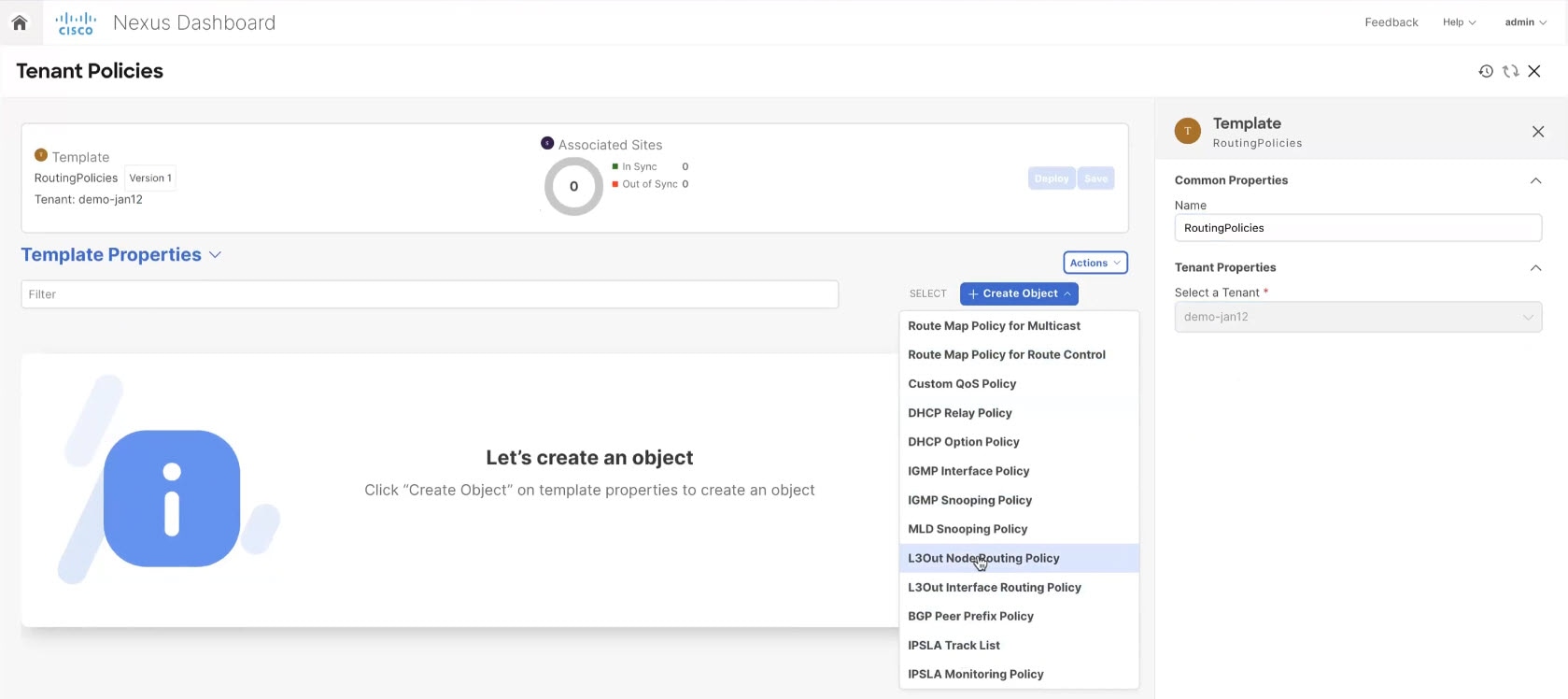
Tenant policies templates
Tenant policies templates allow you to configure the following tenant-wide policies:
-
Route Map Policy for Multicast
-
Route Map Policy for Route Control
-
Custom QoS Policy
-
DHCP Relay Policy
-
DHCP Option Policy
-
IGMP Interface Policy
-
IGMP Snooping Policy
-
MLD Snooping Policy
-
L3Out Node Routing Policy
-
L3Out Interface Routing Policy
-
BGP Peer Prefix Policy
-
IPSLA Track List
-
IPSLA Monitoring Policy
-
Endpoint MAC Tag Policy
-
Endpoint IP Tag Policy
-
NetFlow Record
-
NetFlow Monitor
-
NetFlow Exporter
-
Set Rule Policy
-
Match Rule Policy
For additional information, see Create tenant policy templates.
Understanding match rules and set rules
Prior to Nexus Dashboard release 4.1.1, the match rule and set rule configurations existed within a route map policy for route control in the tenant policy template. This meant that specific match rule and set rule configurations were not available separately, outside of those route map policies.
Beginning with Nexus Dashboard release 4.1.1, you can now configure match rules and set rules at the tenant policy template level, independently from each specific route map policy, which means that you can now reuse individual match rules and set rules across multiple route map policies.
Guidelines and limitations for match rules and set rules
-
These are the unsupported options at the route map, match rule, and set rule levels:
-
Route-map
-
continue action
-
-
Match rule
-
Regex community match
-
AS Path match
-
-
Set rule
-
PcTag
-
-
-
When upgrading to Nexus Dashboard release 4.1.1, a non-disruptive upgrade process is performed (no configurations are pushed to the fabric), and any route maps that were previously configured with inline match rules or set rules are converted to the new route map format, where the match rules and set rules are no longer in line with the route maps themselves and now exist as independent entities outside of the route maps. These independent match rules and set rules that are converted automatically after an upgrade retain the same configurations that they had previously, when they existed in line with the route maps.
-
A route map can only refer to match and set rules within the same tenant policy template. You cannot import a route map into a tenant policy template if its match and set rules have already been imported into a different tenant policy template.
-
Prior to Nexus Dashboard release 4.1.1, importing the match and set rule policies was only allowed through L3Out Related Tenant Policies. Beginning with Nexus Dashboard release 4.1.1, you can now import match and set rule policies outside of L3Out Related Tenant Policies, which allows them to also be consumed by route maps in the tenant policy template.
Configure match rules
A match rule is a condition-based filter or selector that defines the criteria for identifying traffic or routes in a policy.
To configure match rules:
-
Navigate to the Orchestration page.
Manage > Orchestration
-
Click the Tenant Templates tab.
-
Create or edit a tenant policy template.
-
In the Tenant Templates area, click Tenant Policies.
Already-configured tenant policies are shown in the Tenant Policies page.
-
If you want to edit an existing tenant policy, click the circle next to that policy and click Actions > Edit. Go to step 4.
-
If you want to create a new tenant policy:
-
-
In the Tenant Policies area, click Actions > Create Tenant Policy Template.
-
Under Common Properties, in the Name field, provide a name for the template.
-
Under Tenant Properties, from the Select a Tenant dropdown, choose the tenant that you want to associate with this template.
-
Click Ok.
-
-
In the Template Properties page, click Create Object > Match Rule Policy.
-
In the Name field, provide a name for the match rule.
-
In the Match community terms area, click + Add Community Terms to add the necessary community terms to the match rule.
-
In the Match community terms area, click + Add Community Terms.
-
In the Name field, provide a name for the community term.
-
(Optional) In the Description field, provide a description for the community term.
-
Click + Add Community Factor.
-
In the Community field, enter the necessary community information.
For example:
-
Regular communities: 32-bit values used to tag routes for filtering, redistribution, or prioritization. Example entries for a regular community is
regular:as2-nn2:4:15. -
Extended communities: 64-bit values providing additional granularity beyond regular 32-bit BGP communities. Example entries for extended communities are
extended:as4-nn2:5:16orextended:color:35. -
no-export: Prevents a route from being advertised to external BGP peers. -
no-advertise: Prevents a route from being advertised to any peer (internal or external).
-
-
In the Scope field, determine if you want the community to be Transitive or Non-Transitive.
-
(Optional) In the Description field, provide a description for the community.
-
Click the checkmark to accept the community entry.
-
Repeat these steps to add additional community factors, or click Save to save the community term.
-
-
In the Match prefix list area, click + Add Prefix List to add the necessary prefix list to the match rule.
-
In the Prefix field, enter the IP prefix network/length (for example, 192.168.1.0/24).
-
In the Aggregate field, choose True or False.
Aggregate flags are used to allow prefix matches with multiple masks starting with the mask mentioned in the configuration through the maximum mask allowed for the address family of the prefix. This is the equivalent of the
leoption in the prefix-list in NX-OS software (for example,10.0.0.0/8 le 32).The From and To fields below become editable if you choose True in the Aggregate field.
-
In the From field, enter a value below the To value and above the subnet of the IP prefix network/length.
-
In the To field, enter a value above the From value and above the subnet of the IP prefix network/length.
-
Click the checkmark to accept the prefix list entry.
-
Repeat these steps to add additional prefix list entries, or click Ok to save the match rule.
-
Configure set rules
A set rule defines the actions to take when a route or traffic matches specific criteria (defined by a match rule). These actions typically involve modifying attributes such as metrics, next-hop addresses, route tags, or BGP communities.
To configure set rules:
-
Navigate to the Orchestration page.
Manage > Orchestration
-
Click the Tenant Templates tab.
-
Create or edit a tenant policy template.
-
In the Tenant Templates area, click Tenant Policies.
Already-configured tenant policies are shown in the Tenant Policies page.
-
If you want to edit an existing tenant policy, click the circle next to that policy and click Actions > Edit. Go to step 4.
-
If you want to create a new tenant policy:
-
-
In the Tenant Policies area, click Actions > Create Tenant Policy Template.
-
Under Common Properties, in the Name field, provide a name for the template.
-
Under Tenant Properties, from the Select a Tenant dropdown, choose the tenant that you want to associate with this template.
-
Click Ok.
-
-
In the Template Properties page, click Create Object > Set Rule Policy.
-
In the Name field, provide a name for the set rule.
-
(Optional) Click Add Description and provide a description for the set rule.
-
Create an attribute for the set rule.
-
Click Create Attribute.
-
Choose an attribute for the set rule in the Attribute Name field to specify the action that will be taken if the context matches.
You can choose one of the following actions:
-
Set Community
-
Set Route Tag
-
Set Dampening
-
Set Weight
-
Set Next Hop
-
Set Preference
-
Set Metric
-
Set NextHop Propagate
-
Set MultiPath
-
Set Metric Type
-
Set AS Path
-
Set Additional Community
-
-
After you have configured the attribute, click Save.
-
Repeat these steps to add additional set attributes, or click Ok to save the set rule.
-
Create new tenants
You must have a user with either a Super Administrator or Designer read/write role to create and manage tenants.
This section describes how to add a new tenant using the Cisco Nexus Dashboard GUI. If you want to import one or more existing tenants from your fabrics, follow the steps that are described in Import existing tenants instead.
-
Navigate to the Orchestration page.
Manage > Orchestration
-
Click the Tenants tab.
-
In the top right in the Tenants area, click Create Tenant to create a new tenant.
The Create Tenant screen opens.
-
Provide tenant details.
-
Provide the Display Name and optional Description.
The tenant’s Display Name is used throughout the Nexus Dashboard’s GUI whenever the tenant is shown. However, due to object naming requirements on the APIC, any invalid characters are removed and the resulting Internal Name is used when pushing the tenant to fabrics. The Internal Name that will be used when creating the tenant is displayed below the Display Name text box.
You can change the Display Name of the tenant at any time, but the Internal Name cannot be changed after the tenant is created.
-
In the Associated Fabrics section, check all the fabrics that you want to associate with this tenant.
Only the selected fabrics are available for any templates using this tenant.
-
(Optional) For each selected fabric, click the Edit button next to its name and choose one or more security domains.
A restricted security domain allows a fabric administrator to prevent a group of users, such as Tenant A, from viewing or modifying any objects that are created by a group of users in a different security domain, such as Tenant B, when users in both groups have the same assigned privileges. For example, a tenant administrator in Tenant A’s restricted security domain will not be able to see policies, profiles, or users configured in Tenant B’s security domain. Unless Tenant B’s security domain is also restricted, Tenant B can see policies, profiles, or users configured in Tenant A.
A user will always have read-only visibility to system-created configurations for which the user has proper privileges. A user in a restricted security domain can be given a broad level of privileges within that domain without the concern that the user could inadvertently affect another tenant’s physical environment.
Security domains are created using the APIC GUI and can be assigned to various APIC policies and user accounts to control their access. For more information, see the Cisco APIC Basic Configuration Guide.
-
In the Associated Users section, select the Cisco Nexus Dashboard users that are allowed to access the tenant.
Only the selected users are able to use this tenant when creating templates.
-
-
Click Save to finish adding the tenant.
Import existing tenants
You must have a user with either a Super Administrator or Designer read/write role to create and manage tenants.
This section describes how to import one or more existing tenants. If you want to create a new tenant using Cisco Nexus Dashboard, follow the steps that are described in Create new tenants instead.
-
Navigate to the Orchestration page.
Manage > Orchestration
-
Click Tenants.
-
Click Import Tenants to import an existing tenant.
The Import Tenants screen opens.
-
From Select a Fabric drop-down list, choose the fabric.
-
In the Select Tenants to Import, check the name check box.
-
Choose one or more tenants to import and click Import.
The selected tenants will be imported into the Cisco Nexus Dashboard and show in the Manage > Orchestration > Tenants page.
-
Repeat these steps to import tenants from any other fabrics.
Create tenant policy templates
This section describes how to create one or more tenant policy templates. Tenant policy templates allow you to create and configure the following policies:
-
Route Map Policy for Multicast
-
Route Map Policy for Route Control
-
Custom QoS Policy
-
DHCP Relay Policy
-
DHCP Option Policy
-
IGMP Interface Policy
-
IGMP Snooping Policy
-
MLD Snooping Policy
-
L3Out Node Routing Policy
-
L3Out Interface Routing Policy
-
BGP Peer Prefix Policy
-
IPSLA Track List
-
IPSLA Monitoring Policy
-
Endpoint MAC Tag Policy
-
Endpoint IP Tag Policy
-
NetFlow Record
-
NetFlow Monitor
-
NetFlow Exporter
-
Set Rule Policy
-
Match Rule Policy
Follow these steps to create a new tenant policy template.
-
Navigate to the Orchestration page.
Manage > Orchestration
-
Click the Tenant Templates tab.
-
Create a new tenant policy template.
-
In the Tenant Templates area, click Tenant Policies.
-
In the Tenant Policies area, click Actions > Create Tenant Policy Template.
-
Under Common Properties, in the Name field, provide a name for the template.
-
Under Tenant Properties, from the Select a Tenant drop-down list, choose the tenant that you want to associate with this template.
-
Click Ok.
All the policies that you create in this template as described in the following steps will be associated with the chosen tenant and deployed to it when you push the template to a specific fabric.
By default, the new template is empty, so you must add one or more tenant policies as described in the following steps. You don’t have to create every policy available in the template - you can define one or more policies of each type to deploy along with this template. If you don’t want to create a specific policy, simply skip the step that describes it.
-
-
Assign the template to one or more fabrics.
The process for assigning tenant policy templates to fabrics is identical to how you assign application templates to fabrics.
-
In the Template Properties view, click Actions and choose Add/Remove Fabrics.
The Associate Fabrics to template-name page opens.
-
In the Associate Fabrics page, check the check box next to the fabrics where you want to deploy the template.
Note that only the on-premises ACI fabrics support tenant policy templates and will be available for assignment.
-
Click Ok to save.
-
-
Create a Route Map Policy for Multicast.
This policy is part of the overarching Layer 3 Multicast use case. You can use the information in this section as a reference, but we recommend following the full set of steps that are described in Layer 3 Multicast for ACI Fabrics.
-
From the Create Object drop-down list, choose Route Map Policy for Multicast.
-
In the Name field, provide a name for the policy.
-
(Optional) Click Add Description and provide a description for the policy.
-
Click + Create Route Map for Multicast Entries and provide the route map information.
For each route map, you must create one or more route map entries. Each entry is a rule that defines an action based on one or more matching criteria based on the following information:
-
Order - Order is used to determine the order in which the rules are evaluated.
-
Group IP, Src IP, and RP IP - You can use the same multicast route map policy UI for two different use cases-To configure a set of filters for multicast traffic or to restrict a rendezvous point configuration to a specific set of multicast groups. Depending on which use case you’re configuring, you must fill some of the fields in this screen:
-
For multicast filtering, you can use the Source IP and the Group IP fields to define the filter. You must provide at least one of these fields, but can choose to include both. If one of the fields is left blank, it matches all values.
The Group IP range must be between
224.0.0.0and239.255.255.255with a netmask between/4and/32. You must provide the subnet mask.The RP IP (Rendezvous Point IP) is not used for multicast filtering route maps, so leave this field blank.
-
For Rendezvous Point configuration, you can use the Group IP field to define the multicast groups for the RP.
The Group IP range must be between
224.0.0.0and239.255.255.255with a netmask between/4and/32. You must provide the subnet mask.For a Rendezvous Point configuration, the RP IP is configured as part of the RP configuration. If a route-map is used for group filtering it is not necessary to configure an RP IP address in the route-map. In this case, leave the RP IP and Source IP fields empty.
-
-
Action - Action defines the action to perform, either
PermitorDenythe traffic, if a match is found.
-
-
Click the check mark icon to save the entry.
-
Repeat the previous substeps to create any additional route map entries for the same policy.
-
Click Save to save the policy and return to the template page.
-
Repeat this step to create any additional Route Map for Multicast policies.
-
-
Create a Route Map Policy for Route Control.
This policy is part of the overarching L3Out and SR-MPLS L3Out use cases. You can use the information in this section as a reference, but we recommend following the full set of steps that are described in the External Connectivity (L3Out) for ACI Fabrics and Multi-Fabric and SR-MPLS L3Out Handoff for ACI Fabrics articles.
-
From the Create Object drop-down list, choose Route Map Policy for Route Control.
-
In the Name field, provide a name for the policy.
-
(Optional) Click Add Description and provide a description for the policy.
-
Click + Create Entry and provide the route map information.
Beginning with Nexus Dashboard release 4.1.1, you configure set rules and match rules independently from specific route map policies, which means that you can now reuse individual match rules and set rules across multiple route map policies.
-
In the Name field, provide a name for the entry.
-
(Optional) In the Description field, provide a description for the entry.
-
In the Order field, enter a context order for the entry.
Context order is used to determine the order in which contexts are evaluated. The value must be in the
0-9range. -
In the Action field, choose the context action to apply to the entry.
Context action defines the action to perform (
DenyorPermit) if a match is found. If the same value is used for multiple contexts, they are evaluated in the order in which they are defined.
Context entries still have order and context actions associated with them in Nexus Dashboard 4.1.1; however, beginning with Nexus Dashboard 4.1.1, contexts have references to match and set rules, rather than having those configurations existing within the context itself. This means that you must have set rules and match rules already configured for the following steps. See Understanding match rules and set rules for more information.
-
In the Set Rule area, click Select set rule and choose the set rule that you want to associate with this entry, then click Select.
-
In the Match Rules area, click Select match rule and choose one or more match rules that you want to associate with this entry, then click Select.
You can associate multiple match rules with an entry, if necessary.
-
Click Save to save the policy and return to the template page.
-
Repeat this step to create any additional Route Map for Route Control policies.
-
-
Create a Custom QoS Policy.
You can create a custom QoS policy in Cisco APIC to classify ingressing traffic based on its DSCP or CoS values and associate it to a QoS priority level (QoS user class) to properly handle it inside the ACI fabric. Classification is supported only if the DSCP values are present in the IP header or the CoS values are present in the Ethernet header of ingressing traffic. Also, the custom QoS policy can be used to modify the DSCP or CoS values in the header of ingressing traffic.
As an example, custom QoS policies allow you to classify traffic coming into the ACI fabric traffic from devices that mark the traffic based only on the CoS value, such as Layer-2 packets which do not have an IP header.
For detailed information about QoS functionality in ACI fabrics, see Cisco APIC and QoS.
-
From the +Create Object drop-down, choose Custom QoS Policy.
-
In the right properties sidebar, provide the Name for the policy.
-
(Optional) Click Add Description and provide a description for the policy.
-
Click +Add DSCP Mappings and provide the required information.
The DSCP-mapping configuration allows you to associate ingressing traffic, whose DSCP value is within the range that is specified in the mapping, to the specified QoS priority level (class). It also allows you to set the DSCP or CoS values of the ingressing traffic, so that those values can be retained when the traffic egresses the fabric.
-
Retaining the target CoS value for egress traffic requires the configuration of the "Preserve CoS" policy, which is part of the Nexus Dashboard fabric policies.
-
If the "DSCP Target" or "Target CoS" values are set as part of both the DSCP Mapping and CoS Mapping, the values that are specified in the DSCP Mapping have precedence.
For each mapping, you can specify the following fields:
-
DSCP From - The start of the DSCP range.
-
DSCP To - The end of the DSCP range.
-
DSCP Target - The DSCP value to set on ingressing traffic that will be retained for egressing traffic.
-
Target CoS - The CoS value to set on ingressing traffic that will be retained for egressing traffic when "Preserve CoS" is enabled.
-
Priority - The QoS priority class to which the traffic will be assigned.
After you provide the mappings, click the check mark icon to save. Then you can click +Add DSCP Mappings to provide extra mappings within the same policy.
-
-
Click Add to save the policy and return to the template page.
-
Click +Add CoS Mappings and provide the required information.
The DSCP-mapping configuration allows you to associate ingressing traffic (whose DSCP value is within the range that is specified in the mapping) to the specified QoS priority level (class). It also allows you to set the DSCP or CoS values of the ingressing traffic, so that those values can be retained when the traffic egresses the fabric.
-
Retaining the target CoS value for egress traffic requires the configuration of the "Preserve CoS" policy in the Nexus Dashboard fabric policies.
-
In addition, if the "DSCP Target" or "Target CoS" values are set as part of both the DSCP Mapping and CoS Mapping, the values that are specified in the DSCP Mapping have precedence.
For each mapping, you can specify the following fields:
-
Dot1P From - The start of the CoS range.
-
Dot1P To - The end of the CoS range.
-
DSCP Target - The DSCP value to set on ingressing traffic that will be retained for egressing traffic.
-
Target CoS - The CoS value to set on ingressing traffic that will be retained for egressing traffic when "Preserve CoS" is enabled.
-
Priority - The QoS priority class to which the traffic will be assigned.
After you provide the mappings, click the check mark icon to save. Then you can click +Add Cos Mappings to provide extra mappings within the same policy.
-
-
Click Add to save the policy and return to the template page.
-
Repeat this step to create any additional Route Map for Route Control policies.
-
-
Create a DHCP Relay Policy.
This policy is part of the overarching DHCP Relay use case. You can use the information in this section as a reference, but we recommend following the full set of steps that are described in DHCP Relay.
-
From the +Create Object drop-down, choose DHCP Relay Policy.
-
In the right properties sidebar, provide the Name for the policy.
-
(Optional) Click Add Description and provide a description for the policy.
-
Click Add Provider to configure the DHCP server to which you want to relay the DHCP requests originated by the endpoints.
-
Choose the provider type.
When adding a relay policy, you can choose one of the following two types:
-
Application EPG-Specifies the application EPG that includes the DHCP server to which you want to relay the DHCP requests. -
L3 External Network-Specifies the External EPG associated to the L3Out that is used to access the network external to the fabric where the DHCP server is connected.
You can choose any EPG or external EPG that has been created in the Nexus Dashboard and assigned to the tenant you specified, even if you have not yet deployed it to fabrics. If you choose an EPG that hasn’t been deployed, you can still complete the DHCP relay configuration, but you need to deploy the EPG before the relay is available for use.
-
-
Click Select an Application EPG or Select an External EPG (based on the provider type you chose) and choose the provider EPG.
-
In the DHCP Server Address field, provide the IP address of the DHCP server.
-
Enable the DHCP Server VRF Preference option if necessary.
This feature was introduced in Cisco APIC release 5.2(4). For more information on the use cases where it is required see the Cisco APIC Basic Configuration Guide.
-
Click OK to save the provider information.
-
Repeat the previous substeps for any additional providers in the same DHCP Relay policy.
-
Repeat this step to create any additional DHCP Relay policies.
-
-
Create a DHCP Option Policy.
This policy is part of the overarching DHCP Relay use case. You can use the information in this section as a reference, but we recommend following the full set of steps that are described in DHCP Relay.
-
From the +Create Object drop-down, choose DHCP Option Policy.
-
In the right properties sidebar, provide the Name for the policy.
-
(Optional) Click Add Description and provide a description for the policy.
-
Click Add Option.
-
Provide option details.
For each DHCP option, provide the following:
-
Name - While not technically required, we recommend using the same name for the option as listed in RFC 2132.
For example,
Name Server. -
Id - Provide the value if the option requires one.
For example, a list of name servers available to the client for the Name Server option.
-
Data - Provide the value if the option requires one.
For example, a list of name servers available to the client for the Name Server option.
-
-
Click OK to save.
-
Repeat the previous substeps for any additional options in the same DHCP Option policy.
-
Repeat this step to create any additional DHCP Option policies.
-
-
Create an IGMP Interface Policy.
IGMP snooping examines IP multicast traffic within a bridge domain to discover the ports where interested receivers reside. Using the port information, IGMP snooping can reduce bandwidth consumption in a multiaccess bridge domain environment to avoid flooding the entire bridge domain.
For detailed information on IGMP snooping in ACI fabrics, see the "IGMP Snooping" chapter of the Cisco APIC Layer 3 Networking Configuration Guide for your release.
-
From the +Create Object drop-down, choose IGMP Interface Policy.
-
In the right properties sidebar, provide the Name for the policy.
-
(Optional) Click Add Description and provide a description for the policy.
-
Provide policy details.
-
Allow Version 3 ASM - Allow accepting IGMP version 3 source-specific reports for multicast groups outside of the SSM range. When this feature is enabled, the switch creates an (S,G) mroute entry if it receives an IGMP version 3 report that includes both the group and source even if the group is outside of the configured SSM range. This feature is not required if hosts send (*, G) reports outside of the SSM range, or send (S,G) reports for the SSM range.
-
Fast Leave - Option that minimizes the leave latency of IGMPv2 group memberships on a given IGMP interface because the device does not send group-specific queries. When Fast Leave is enabled, the device removes the group entry from the multicast routing table immediately upon receiving a leave message for the group. The default is disabled.
Use this only when there is only one receiver behind the BD/interface for a given group.
-
Report Link Local Groups - Enables sending reports for groups in 224.0.0.0/24. Reports are always sent for nonlink local groups. By default, reports are not sent for link local groups.
-
IGMP Version - IGMP version that is enabled on the bridge domain or interface. The IGMP version can be 2 or 3. The default is 2.
-
Advanced Settings - Click the arrow next to this section to expand.
-
Group Timeout - Group membership interval that must pass before the router decides that no members of a group or source exist on the network. Values range 3-65,535 seconds. The default is 260 seconds.
-
Query Interval - Sets the frequency at which the software sends IGMP host query messages. Values can range 1-18,000 seconds. The default is 125 seconds.
-
Query Response Interval - Sets the response time that is advertised in IGMP queries. Values can range 1-25 seconds. The default is 10 seconds.
-
Last Member Count - Sets the number of times that the software sends an IGMP query in response to a host leave message. Values can range 1-5. The default is 2.
-
Last Member Response Time - Sets the query interval waited after sending membership reports before the software deletes the group state. Values can range 1-25 seconds. The default is 1 second.
-
Startup Query Count - Configures snooping for several queries that are sent at startup when you do not enable Protocol Independent Multicast because multicast traffic does not need to be routed. Values can range 1-10. The default is 2 messages.
-
Startup Query Interval - This configures the IGMP snooping query interval at startup. The range is from 1 second to 18,000 seconds. The default is 125 seconds.
-
Querier Timeout - Sets the query timeout that the software uses when deciding to take over as the querier. Values can range 1-65,535 seconds. The default is 255 seconds.
-
Robustness Variable - Sets the robustness variable. You can use a larger value for a lossy network. Values can range 1-7. The default is 2.
-
State Limit Route Map - Used with Reserved Multicast Entries feature.
The route map policy must be already created as described in Step 2.
-
Report Policy Route Map - Access policy for IGMP reports that is based on a route-map policy. IGMP group reports will only be chosen for groups that are allowed by the route-map.
The route map policy must be already created as described in Step 2.
-
Static Report Route Map - Statically binds a multicast group to the outgoing interface, which is handled by the switch hardware. If you specify only the group address, the (*, G) state is created. If you specify the source address, the (S, G) state is created. You can specify a route-map policy name that lists the group prefixes, group ranges, and source prefixes. A source tree is built for the (S, G) state only if you enable IGMPv3.
The route map policy must be already created as described in Step 2.
-
Maximum Multicast Entries - Limit the mroute states for the BD or interface that are created by IGMP reports. Default is disabled and no limit is enforced. Valid range is 1-4294967295.
-
-
-
Repeat this step to create any additional IGMP Interface policies.
-
-
Create an MLD Snooping Policy.
Multicast Listener Discovery (MLD) snooping enables the efficient distribution of IPv6 multicast traffic between hosts and routers. It is a Layer 2 feature that restricts IPv6 multicast traffic within a bridge domain to a subset of ports that have sent or received MLD queries or reports. In this way, MLD snooping provides the benefit of conserving the bandwidth on those segments of the network where no node has expressed interest in receiving the multicast traffic. This reduces the bandwidth usage instead of flooding the bridge domain, and also helps hosts and routers save unwanted packet processing.
For detailed information on MLD snooping in ACI fabrics, see the "MLD Snooping" chapter of the Cisco APIC Layer 3 Networking Configuration Guide for your release.
-
From the +Create Object drop-down, choose MLD Snooping Policy.
-
In the right properties sidebar, provide the Name for the policy.
-
(Optional) Click Add Description and provide a description for the policy.
-
Provide policy details.
-
Admin State - Enables or disables the MLD snooping feature.
-
Fast Leave Control - Allows you to turn on or off the fast-leave feature on a per bridge domain basis. This applies to MLDv2 hosts and is used on ports that are known to have only one host doing MLD behind that port.
Default is
disabled. -
Querier Control - Enables or disables MLD snooping querier processing. MLD snooping querier supports the MLD snooping in a bridge domain where PIM and MLD are not configured because the multicast traffic does not need to be routed.
Default is
disabled. -
Querier Version - Allows you to choose the querier version.
Default is
Version2. -
Advanced Settings - Click the arrow next to this section to expand.
-
Query Interval - Sets the frequency at which the software sends MLD host query messages. Values can range 1-18,000 seconds.
The default is 125 seconds.
-
Query Response Interval - Sets the response time that is advertised in MLD queries. Values can range 1-25 seconds .
The default is 10 seconds.
-
Last Member Query Interval - Sets the query response time after sending membership reports before the software deletes the group state. Values can range 1-25 seconds.
The default is 1 second.
-
Start Query Count - Configures snooping for several queries that are sent at startup when you do not enable PIM because multicast traffic does not need to be routed. Values can range 1-10 .
The default is 2.
-
Start Query Interval - Configures a snooping query interval at startup when you do not enable PIM because multicast traffic does not need to be routed. Values can range 1-18,000 seconds.
The default is 31 seconds.
-
-
-
Repeat this step to create any additional MLD Snooping policies.
-
-
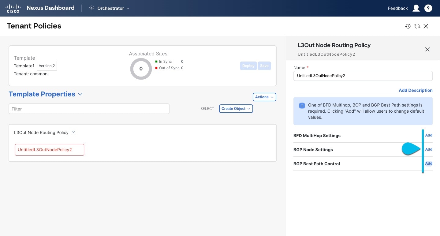
Create an L3Out Node Routing Policy.
This policy is part of the overarching L3Out and SR-MPLS L3Out configuration use case. You can use the information in this section as a reference, but we recommend following the full set of steps that are described in External Connectivity (L3Out) for ACI Fabrics.
-
In the main pane, choose Create Object > L3Out Node Routing Policy.
 Create Object
 -
Provide the Name for the policy, and Add at least one of the BFD MultiHop Settings, BGP Node Settings, or BGP Best Path Control options.
 BFD MultiHop Settings
-
BFD MultiHop Settings - provides forwarding failure detection for destinations with more than one hop.
In this case, a MultiHop session is created between the source and destination instead of the interface like in single-hop scenarios.
BFD MultiHop configuration requires Cisco APIC release 5.0(1) or later.
-
BGP Node Settings - allows you to configure BGP protocol timer and sessions settings for BGP adjacencies between BGP peers.
-
BGP Best Path Control - enables
as-path multipath-relax, which allows load-balancing between multiple paths that are received from different BGP ASN.
-
-
-
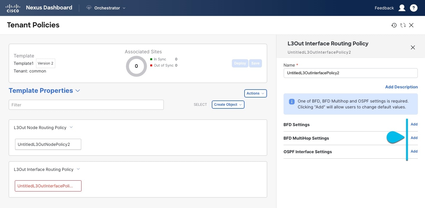
Create an L3Out Interface Routing Policy.
This policy is part of the overarching L3Out and SR-MPLS L3Out configuration use case. You can use the information in this section as a reference, but we recommend following the full set of steps that are described in External Connectivity (L3Out) for ACI Fabrics.
-
In the main pane, choose Create Object > L3Out Interface Routing Policy.
-
Provide the Name for the policy, and define the BFD Settings, BFD Multi-Hop Settings, and OSPF Interface Settings.
 Create ObjectL3Out
-
BFD Settings - specifies BFD parameters for BFD sessions established between devices on interfaces that are directly connected.
When multiple protocols are enabled between a pair of routers, each protocol has its own link failure detection mechanism, which may have different timeouts. BFD provides a consistent timeout for all protocols to allow consistent and predictable convergence times.
-
BFD MultiHop Settings - specifies BFD parameters for BFD sessions established between devices on interfaces that are not directly connected.
You can configure these settings at the node level as mentioned in the section "Tenant Policy Template: Node Routing Group Policy" in External Connectivity (L3Out) for ACI Fabrics, in which case the interfaces inherit those settings, or you can overwrite the node-level settings for individual interfaces in the Interface Routing group policy.
BFD multi-hop configuration requires Cisco APIC release 5.0(1) or later.
-
OSPF Interface Settings - allows you to configure interface-level settings such as OSPF network type, priority, cost, intervals and controls.
This policy must be created when deploying an L3Out with OSPF.
-
-
-
Create a BGP Peer Prefix Policy.
This policy is part of the overarching L3Out and SR-MPLS L3Out configuration use case. You can use the information in this section as a reference, but we recommend following the full set of steps that are described in External Connectivity (L3Out) for ACI Fabrics.
-
In the main pane, choose Create Object > BGP Peer Prefix Policy.
-
Provide the Name for the policy, and define the Max Number of Prefixes and the Action to take if the number is exceeded.
The following actions are available:
-
Log
-
Reject
-
Restart
-
Shutdown
-
-
In Max Number of Prefixes field enter the value. The default value is 20000.
-
In Threshold Percentage field enter the value. The default value is 75.
-
-
Create an IP SLA Monitoring Policy.
This policy is part of the overarching L3Out and SR-MPLS L3Out configuration use case. You can use the information in this section as a reference, but we recommend following the full set of steps that are described in the External Connectivity (L3Out) for ACI Fabrics.
-
In the main pane, choose Create Object > IP SLA Monitoring Policy.
-
Provide the Name for the policy, and define its settings.
If you choose
HTTPfor the SLA Type, your fabric must be running Cisco APIC release 5.1(3) or later.
-
-
Create an IP SLA Track List.
This policy is part of the overarching L3Out and SR-MPLS L3Out configuration use case. You can use the information in this section as a reference, but we recommend following the full set of steps that are described in the External Connectivity (L3Out) for ACI Fabrics.
-
In the main pane, choose Create Object > IP SLA Track List.
-
Provide the Name for the policy.
-
Choose the Type.
The definition of a route being available or not available can be based on
Threshold PercentageorThreshold Weight. Based on your threshold choice, you can enter the values in Percentage Down Value and Percentage Up Value or Weight Down Value and Weight Up Value. -
Click +Add Track List to Track Member Relation to add one or more track members to this track list.
You must choose a bridge domain or an L3Out to associate with the track member. If you do not already have the bridge domain (BD) or L3Out that is created, you can skip adding a track member, save the policy without assigning one, and come back to it after you have created the BD or L3Out.
-
In the Add Track List to Track Member Relation dialog, provide the Destination IP, Scope Type, and choose the IP SLA Monitoring Policy.
The scope for the track list can be either bridge domain or L3Out. The IP SLA Monitoring policy is the one you created in the previous step.
-
-
Click Save to save the changes you’ve made to the template.
When you save (or deploy) the template to one or more fabrics, the Nexus Dashboard will verify that the specified nodes or interfaces are valid for the fabrics and will return an error.
-
Click Deploy to deploy the template to the associated fabrics.
The process for deploying tenant policy templates is identical to how you deploy application templates.
If you have previously deployed this template but made no changes to it since, the Deploy summary indicates that there are no changes, and you can choose to redeploy the entire template. In this case, you can skip this step.
Otherwise, the Deploy to fabrics page shows you a summary of the configuration differences that will be deployed to fabrics. Note that in this case only the difference in configuration is deployed to the fabrics. If you want to redeploy the entire template, you must deploy when to sync the differences, and then redeploy again to push the entire configuration as described in the previous paragraph.