Troubleshooting Installations, Upgrades, and Reboots

This chapter contains the following sections:

Increasing CPU Cycle Reservation for Orchestrator VMs

Cisco ACI Multi-Site Orchestrator VMs require a certain amount of dedicated CPU cycles. While new deployments apply CPU cycle reservation automatically, if you upgrade the Orchestrator from a release prior to Release 2.1(1), you will need to update each Orchestrator VM's settings manually.

Configuring appropriate CPU cycle reservation can resolve or help prevent a number of seemingly random issues, such as:

  • Orchestrator GUI items requiring one or more retries to load.

  • One or more nodes changing to Unknown status and then resolving back to Ready some time later on its own:

    # docker node ls
    ID                            HOSTNAME    STATUS      AVAILABILITY    MANAGER STATUS  ENGINE VERSION
    t8wl1zoke0vpxdl9fysqu9otb     node1       Ready       Active          Reachable       18.03.0-ce
    kyriihdfhy1k1tlggan6e1ahs *   node2       Unknown     Active          Reachable       18.03.0-ce
    yburwactxd86dorindmx8b4y1     node3       Ready       Active          Leader          18.03.0-ce
    
  • Transient heartbeat misses in the Orchestrator logs (located in /var/log/messages) with the following example log entries:

    node2 dockerd: [...] level=error msg="agent: session failed" backoff=100ms
        error="rpc error: code = Canceled desc = context canceled" module=node/agent [...]
    node2 dockerd: [...] level=error msg="heartbeat to manager [...] failed"
        error="rpc error: code = Canceled desc = context canceled" [...]
    

To update the CPU cycle reservation setting, repeat the following steps for each Orchestrator VM:

Procedure


Step 1

Log in to the vSphere client.

Step 2

Navigate to the ESX host where your Orchestrator VM is located.

Step 3

Shut down the VM.

Step 4

Right click the VM and choose Edit Settings

Step 5

In the Virtual Hardware tab, expand the CPU category.

Step 6

In the Reservation field, enter 10 GHz.

Step 7

Click OK to save the changes.

Step 8

Power on the VM and wait for the Orchestrator cluster to stabilize with all nodes healthy.


Enabling NTP for Orchestrator Nodes

Not having clock synchronization configured for Orchestrator nodes may cause issues, such as random GUI session log off due to authentication token expiration.

Typically, you provide the Network Time Protocol (NTP) server details for the Orchestrator nodes during Multi-Site Orchestrator installation. However, if for any reason you have not specified NTP settings, you can configure them using the following steps.

Procedure


Step 1

Log in directly to an Orchestrator VM.

Step 2

Change into the scripts directory.

# cd /opt/cisco/msc/scripts
Step 3

Configure the NTP settings for the node.

In the following command:
  • '-tz <time-zone>' specifies the time zone you are in

  • '-ne ' enables NTP

  • '-ns <ntp-server>' specifies the NTP server

# ./svm-msc-tz-ntp  -tz <time-zone> -ne -ns <ntp-server>

For example:

# ./svm-msc-tz-ntp -tz US/Pacific -ne -ns ntp.esl.cisco.com
svm-msc-tz-ntp: Start
svm-msc-tz-ntp: Executing timedatectl set-timezone US/Pacific
svm-msc-tz-ntp: Executing sed -i 's|^server|\# server|' /etc/ntp.conf
svm-msc-tz-ntp: Executing timedatectl set-ntp true
svm-msc-tz-ntp: Sleeping 10 seconds
svm-msc-tz-ntp: Checking NTP status
svm-msc-tz-ntp: Executing ntpstat;ntpq -p
unsynchronised
   polling server every 64 s
     remote           refid      st t when poll reach   delay   offset  jitter
==============================================================================
mtv5-ai27-dcm10 .GNSS.           1 u    -   64    1    1.581   -0.002   0.030
Step 4

Verify NTP configuration.

You can verify that NTP is enabled using the following command:

# ntpstat;ntpq -p
unsynchronised
   polling server every 64 s
     remote           refid      st t when poll reach   delay   offset  jitter
==============================================================================
*mtv5-ai27-dcm10 .GNSS.           1 u   14   64    1    3.522   -0.140   0.128

You can also confirm that the correct date and time are set:

# date
Mon Jul  8 14:19:26 PDT 2019
Step 5

Repeat the procedure on each Orchestrator node.


Updating DNS

This section describes how to update the DNS server address for your Multi-Site Orchestrator cluster. Note that this procedure applies to MSO OVA deployments in VMware ESX only and not Application Services Engine or Nexus Dashboard deployments.

Procedure


Step 1

SSH in to one of the cluster nodes as the root user.

Step 2

Update the DNS configuration.

Use the nmcli command to update the DNS server IP address:

# nmcli connection modify eth0 ipv4.dns "<dns-server-ip>"

If you want to provide multiple DNS server IPs, use a space-separated list:

# nmcli connection modify eth0 ipv4.dns "<dns-server-ip-1> <dns-server-ip-2>"
Step 3

Restart the network interface you updated.

For the changes to apply, you need to restart the eth0 interface:

# nmcli connection down eth0 && nmcli connection up eth0
Step 4

Reboot the node.

Step 5

Repeat the previous steps for the other two nodes.


Restarting a Single Node of the Cluster if it Goes Down Temporarily

This section describes how to restart a single node of the cluster if it goes down temporarily.

Procedure


Restart the node which was down. No additional steps are required and the cluster recovers by itself.


Restarting Two Nodes of Cluster that Go Down Temporarily

This sections describes how to restart two nodes of the cluster that go down temporarily.

Procedure


Step 1

At this point due to lack of a quorum of 3 manager nodes in the Docker swarm, Multi-Site will not be available. Cisco recommends that you back up the MongoDB prior to any recovery attempts.

For more information, see Backing Up the MongoDB for Cisco ACI Multi-Site.

Step 2

Restart the 2 nodes which were down. No additional steps are required and the cluster recovers by itself.


Backing Up the MongoDB for Cisco ACI Multi-Site

Cisco recommends that you back up the MongoDB prior to any Cisco ACI Multi-Site Orchestrator upgrades or downgrades, as described in this section.


Note

You can back up the database only when the Orchestrator cluster is up, which requires at least 2 nodes to be up and running.


Procedure


Step 1

Log in to the Cisco ACI Multi-Site Orchestrator virtual machine (VM).

Step 2

Execute the Cisco ACI Multi-Site Orchestrator backup script:

# ~/msc_scripts/msc_db_backup.sh

The msc_backup_<date+%Y%m%d%H%M>.archive file is created.

Step 3

Copy the msc_backup_<date+%Y%m%d%H%M>.archive file to a safe place.


Restoring the MongoDB for Cisco ACI Multi-Site

This section describes how to restore the MongoDB for Cisco ACI Multi-Site.

Procedure


Step 1

Log in to the Multi-Site virtual machine (VM).

Step 2

Copy your msc_backup_<date+%Y%m%d%H%M>.archive file to the VM.

Step 3

Execute the Multi-Site DB restore script:

# ~/msc_scripts/msc_db_restore.sh
Step 4

Push the schemas again by executing the python script:

# msc_push_schemas.py

Custom Certificates Troubleshooting

The following sections describe how to resolve common issues when using custom SSL certificates with Multi-Site Orchestrator.

Unable to Load the Orchestrator GUI

If you are unable to load the Orchestrator GUI page after installing and activating a custom certificate, it is possible that the certificates were not copied correctly to each Orchestrator node. You can resolve this issue by recovering the default certificates and then repeating the new certificate installation procedure again.

To recover the default Orchestrator certificates:

Procedure


Step 1

Log in to each Orchestrator node directly.

Step 2

Change into the certificates directory:

# cd /data/msc/secrets
Step 3

Replace the msc.key and msc.crt files with msc.key_backup and msc.crt_backup files respectively.

Replace the msc.key and msc.crt files with msc.key_backup and msc.crt_backup files respectively.

Step 4

Restart the Orchestrator GUI service.

# docker service update msc_ui --force
Step 5

Re-install and activate the new certificates as described in previous sections.


Adding a New Orchestrator Node to the Cluster

If you add a new node to you Multi-Site Orchestrator cluster:

Procedure


Step 1

Log in to the Orchestrator GUI.

Step 2

Re-activate the key you are using as described in previous sections.


Unable to Install a New Keyring after the default Keyring Expired

If you are unable to install a new Keyring after the default Keyring expired, it is possible that custom Keyring is not installed on the cluster nodes.

You can resolve this issue by deleting the old default Keyring and creating a new Keyring using steps mentioned below:

Procedure


Step 1

Execute the following commands on all the nodes in the cluster:

cd /data/msc/secrets
rm -rf /data/msc/secrets/msc.key
rm -rf /data/msc/secrets/msc.crt
rm -rf /data/msc/secrets/msc.key_backup
rm -rf /data/msc/secrets/msc.crt_backup
!
!
openssl req -newkey rsa:2048 -nodes -keyout /data/msc/secrets/msc.key -x509 -days 365 -out /data/msc/secrets/msc.crt -subj '/CN=MSC'
cp /data/msc/secrets/msc.key /data/msc/secrets/msc.key_backup
cp /data/msc/secrets/msc.crt /data/msc/secrets/msc.crt_backup
cd /data/msc/secrets
chmod 777 msc.key
chmod 777 msc.key_backup
chmod 777 msc.crt
chmod 777 msc.crt_backup
Step 2

Execute the following command to force update of msc_ui service:

# docker service update msc_ui --force
Step 3

Once the update completes, check if all the replicas of msc_ui are healthy.

[root@node1 ~]# docker service ls
...
rqs0607lgixg     msc_ui     global     3/3    msc-ui:3.1.1i   
*:443->443/tcp
Step 4

Log in to any of the MSO nodes using any browser. If the browser is stuck in a loop while accepting the certificate details or displays a white screen, refresh the page one or two times until the GUI is displayed normally again.

Step 5

Log in using the username and password and activate the Keyring by following the steps described in the ‘Activating Custom Keyring’ section.


Replacing a Single Node of the Cluster with a New Node

This section describes how to replace a single node of the cluster with a new node.

In this scenario node 1 goes down and you want to replace node 1 with a new node.

Procedure


Step 1

On any existing node, get the ID of the node that is down (node1). Execute the following command:

root@node2 ~]# docker node ls
ID                           HOSTNAME  STATUS  AVAILABILITY   MANAGER STATUS
11624powztg5tl9nlfoubydtp *  node2     Ready   Active         Leader
fsrca74nl7byt5jcv93ndebco    node3     Ready   Active         Reachable
wnfs9oc687vuusbzd3o7idllw    node1     Down    Active         Unreachable
Step 2

You must demote node1, execute the following command:

[root@node2 ~]# docker node demote <node ID>
Manager <node ID> demoted in the swarm.

<node ID> is where you received the node ID from step 1.

Step 3

Remove node1 which is down before adding the new node, execute the following command:

[root@node2 ~]# docker node rm <node ID>
Step 4

On any existing node, change to the /opt/cisco/msc/builds/<build_number>/prodha directory:

Example:

# cd /opt/cisco/msc/builds/<build_number>/prodha
Step 5

Take note of the token. On any existing node, execute the following command:

[root@node1 prodha]# docker swarm join-token manager
docker swarm join --token SWMTKN-1-4yaodn4nj8nek0qghh4dfzn6zm9o9p29rjisdikhjpvwu8bgmw-0ig2g62e0fe62cq2hbexk6xgv \
1.1.1.1:2376
Step 6

Taken note of IP address of the new leader. On any existing node, enter the following command:

Example:


[root@node1 prodha]# docker node ls
ID                          HOSTNAME   STATUS   AVAILABILITY   MANAGER STATUS
pjicie1wlcgkoef1x9s0td7ac   node1      Down     Active         Reachable
qy6peh6wtsbsaf9cpyh2wr5f6   node2      Ready    Active         Leader
tfhhvzt7qx9lxkqalbxfwknsq   node3      Ready    Active         Reachable
Step 7

On the leader node (node2), take note of the IP address:

# ifconfig
inet 10.23.230.152 netmask 255.255.255.0 broadcast 192.168.99.255
Step 8

Prepare the new third node. Set the correct hostname for the new node:

Example:

# hostnamectl set-hostname <node name>
Step 9

Change to the /opt/cisco/msc/builds/<build_number>/prodha directory:

Example:

# cd /opt/cisco/msc/builds/<build_number>/prodha
Step 10

Join the new node to the swarm:

Example:

[root@node1 prodha]# ./msc_cfg_join.py <token> <address of leader>

<token> is where you received the token information from step 5.

<address of leader> is where you received the leader IP address in step 7.

Step 11

On any node, change to the /opt/cisco/msc/builds/<build_number>/prodha directory:

Example:

# cd /opt/cisco/msc/builds/<build_number>/prodha
Step 12

On any node, execute the following command:

[root@node1 prodha]# ./msc_deploy.py

At this point all service should be up and database replicated.

Replacing Two Existing Nodes of the Cluster with New Nodes

This section describes how to replace two existing nodes of the cluster with new nodes. The instructions here are for the Orchestrator deployments in ESX VMware VMs, which use Docker swarm for the cluster.

At this point due to lack of a quorum of 3 manager nodes in the Docker swarm, Multi-Site Orchestrator will not be available. We recommend that you back up the DB prior to any recovery attempts. For more information, see Backing Up the MongoDB for Cisco ACI Multi-Site.

Procedure


Step 1

Bring up two new nodes and set appropriate node names for each new node.

After you bring up a new node, you can assign its node name using the following command:

# hostnamectl set-hostname <node-name>

Keep in mind that all 3 node names must be unique within the cluster.

Step 2

On the only live node which was previously part of swarm, remove the other nodes that are down.

  1. SSH into the only live node that was part of the swarm.

  2. View the status of all nodes.

    # docker node ls
    ID                            HOSTNAME   STATUS   AVAILABILITY  MANAGER     STATUS
    g3mebdulaed2n0cyywjrtum31     node2      Down     Active        Reachable
    ucgd7mm2e2divnw9kvm4in7r7     node1      Ready    Active        Leader
    zjt4dsodu3bff3ipn0dg5h3po *   node3      Down     Active        Reachable
  3. Delete any nodes with the Down status.

    # docker node rm <node-id>

    For example:

    # docker node rm g3mebdulaed2n0cyywjrtum31
Step 3

Re-initiate the Docker swarm.

While still logged into the only live node, perform the following steps.

  1. Leave the existing swarm.

    # docker swarm leave --force
  2. Change into the Orchestrator scripts directory.

    # cd /opt/cisco/msc/builds/<build-number>/prodha
  3. Re-initiate a new swarm.

    # ./msc_cfg_init.py

    The command will return a token and IP address you will need to use on the two new nodes to join them into the new cluster.

Step 4

Join the two new nodes into the cluster.

On each of the new nodes, perform the following steps.

  1. SSH in to the node.

  2. Change into the Orchestrator scripts directory.

    # cd /opt/cisco/msc/builds/<build-number>/prodha
  3. Join the node into the cluster.

    In the following command,

    • Replace <token>, with the token you received from the ./msc_cfg_init.py command when you re-initiated the Docker swarm in the previous step.

    • Replace <ip-address> with the IP address of the first node, which you also received in the previous step.

    # ./msc_cfg_join.py <token> <ip-address>
Step 5

Deploy the new configuration.

You can run the following command from any node in the new cluster. The script is located in the same /opt/cisco/msc/builds/<build-number>/prodha scripts directory.

# ./msc_deploy.py

Relocating Multi-Site Nodes to a Different Subnet

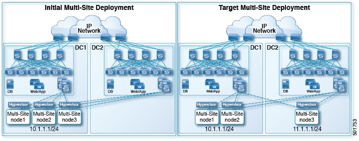
This section describes how to relocate one or more Multi-Site nodes from one subnet to another. This is a common task when Multi-Site is deployed within a single data center and the goal is to spread the nodes across one or more data centers. It is important to move a single node at a time to maintain redundancy during the migration.

Figure 1. Cisco ACI Multi-Site Deployments

The example procedure below shows the relocation of Multi-Site node3 from data center 1 where the management subnet uses a 10.1.1.1/24 subnet, to data center 2 where the management subnet uses a 11.1.1.1/24 subnet.

Procedure


Step 1

On node1, demote node3:

Example:

[root@node1 prodha]# docker node demote node3
Step 2

Power down node3 virtual machine (VM).

Step 3

Remove node3 from the cluster:

Example:

[root@node1 prodha]# docker node rm node3
Step 4

Deploy the new Multi-Site VM (same version as node1 and node2) to the data center. Configure with the new IP details and ensure the hostname ‘node3’ gets assigned.

Step 5

Power up node3 in data center 2 and test the connectivity to node1 and node2:

Example:

[root@node3 prodha]# ping [node1_IP]
[root@node3 prodha]# ping [node2_IP]
Step 6

On node1, get the join token from node1 to join node3 to the cluster:

Example:

[root@node1 prodha]# docker swarm join-token manager
To add a manager to this swarm, run the following command:

docker swarm join --token \
SWMTKN-1-4plaanp2uqpkjm2nidsxg9u7it0dd8hkihwjq9wvrz5heykl2n-98eo0onpacvxrrgf84juczdve \
10.1.1.1:2377

[root@node1 prodha~]#
Step 7

On node3, join swarm using the join token from step 6.

Example:

[root@node3 prodha]# docker swarm join --token \
SWMTKN-1-4plaanp2uqpkjm2nidsxg9u7it0dd8hkihwjq9wvrz5heykl2n-98eo0onpacvxrrgf84juczdve \
10.1.1.1:2377
Step 8

On any node, make sure the nodes are heathly. Verify that the STATUS is Ready, the AVAILABILITY is Active for each node, and the MANAGER STATUS is Reachable except for only one showing Leader:

Example:

[root@node1 ~]# docker node ls
ID                           HOSTNAME   STATUS   AVAILABILITY   MANAGER STATUS
p71zqw77kwnu8z6sr1w0uq2g0    node2      Ready    Active         Leader
q5orng9hd4f0vxneqeehixxwt    node3      Ready    Active         Reachable
ryag1u9ej33pfvrjvqgj4tjr4 *  node1      Ready    Active         Reachable
[root@node1 ~]#
Step 9

Update the swarm label for node3:

Example:

[root@node1 prodha]# docker node update node3 --label-add msc-node=msc-node3
Step 10

On any node, check the status of all the docker services. For example, make sure it states 1/1 (1 out of 1) or 3/3 (3 out of 3). This may take up to 15 minutes to sync up.

Example:

[root@node1 ~]# docker service ls
ID             NAME                     MODE         REPLICAS   IMAGE                             PORTS
3kv2qtu3gjmk   msc_kongdb               replicated   1/1        msc-postgres:9.4
5fs0lg9bbbg1   msc_kong                 global       3/3        msc-kong:1.1
jrxade8o2nwn   msc_schemaservice        global       3/3        msc-schemaservice:1.2.0.206
kyq1myno38ry   msc_backupservice        global       3/3        msc-backupservice:1.2.0.206
ltx85gitz85u   msc_executionengine      replicated   1/1        msc-executionengine:1.2.0.206
n4skpiij90t1   msc_ui                   global       3/3        msc-ui:1.2.0.206                  *:80->80/tcp,*:443->443/tcp
o2h8vp3clznd   msc_mongodb1             replicated   1/1        msc-mongo:3.4
q2udphffzb7g   msc_consistencyservice   replicated   1/1        msc-consistencyservice:1.2.0.206
qr1zbd0y18u1   msc_platformservice      global       3/3        msc-platformservice:1.2.0.206
rsb7ki0zxafa   msc_mongodb2             replicated   1/1        msc-mongo:3.4
uiu25mz5h7m9   msc_userservice          global       3/3        msc-userservice:1.2.0.206
xjrp2jbws4pz   msc_auditservice         replicated   1/1        msc-auditservice:1.2.0.206
xtsdns1iy52i   msc_syncengine           replicated   1/1        msc-syncengine:1.2.0.206
ypie99rvielj   msc_mongodb3             replicated   1/1        msc-mongo:3.4
zn03gxpleu1s   msc_siteservice          global       3/3        msc-siteservice:1.2.0.206
[root@node1 ~]#
Step 11

Delete the original node3 VM that you powered down in data center 1.