Support for Multiple Encapsulation for L3Outs With SVI

Support for Multiple Encapsulation for L3Outs with SVI

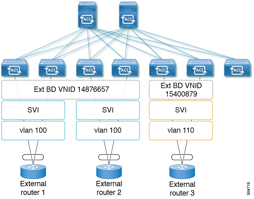
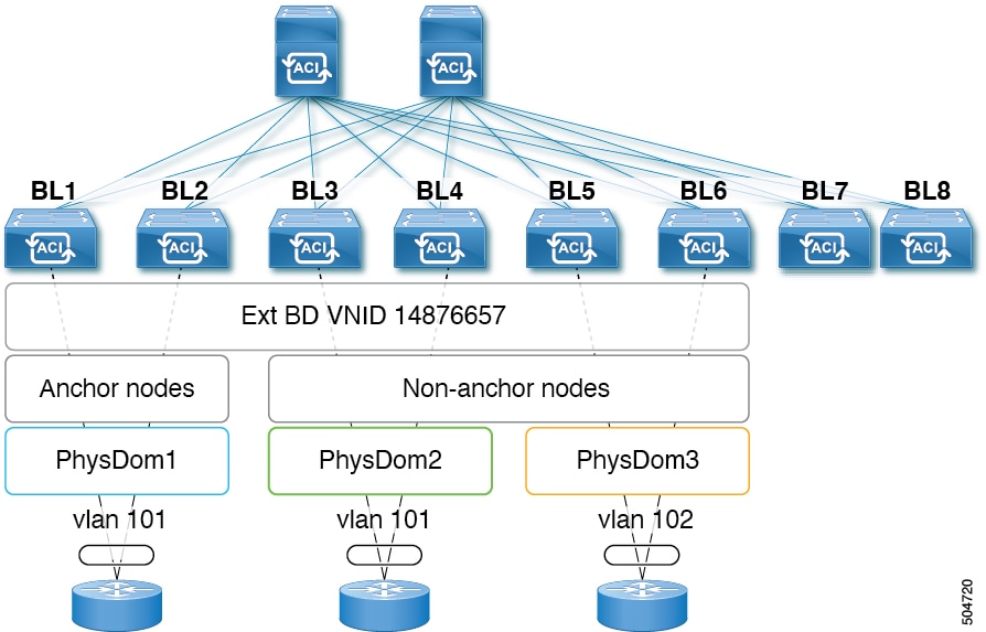
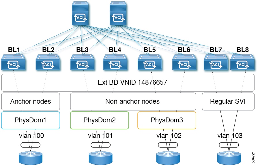
When an L3Out is configured with SVI interfaces on different leaf switches using the same encapsulation VLAN, the SVI VLAN will be mapped to the same VXLAN network identifier (VNID). This forms a single bridge domain (external bridge domain) and broadcast domain across the fabric. An SVI interface configured with a different VLAN will form a separate external bridge domain as illustrated in the diagram below. Prior to Cisco Application Centric Infrastructure (ACI) release 5.2(3) it was not possible to create a single external bridge domain with different encapsulation VLANs on different switches.

Figure 1. Separate VNID Associated to External Bridge Domains with Different Encapsulation (pre-ACI 5.2(3) Releases)

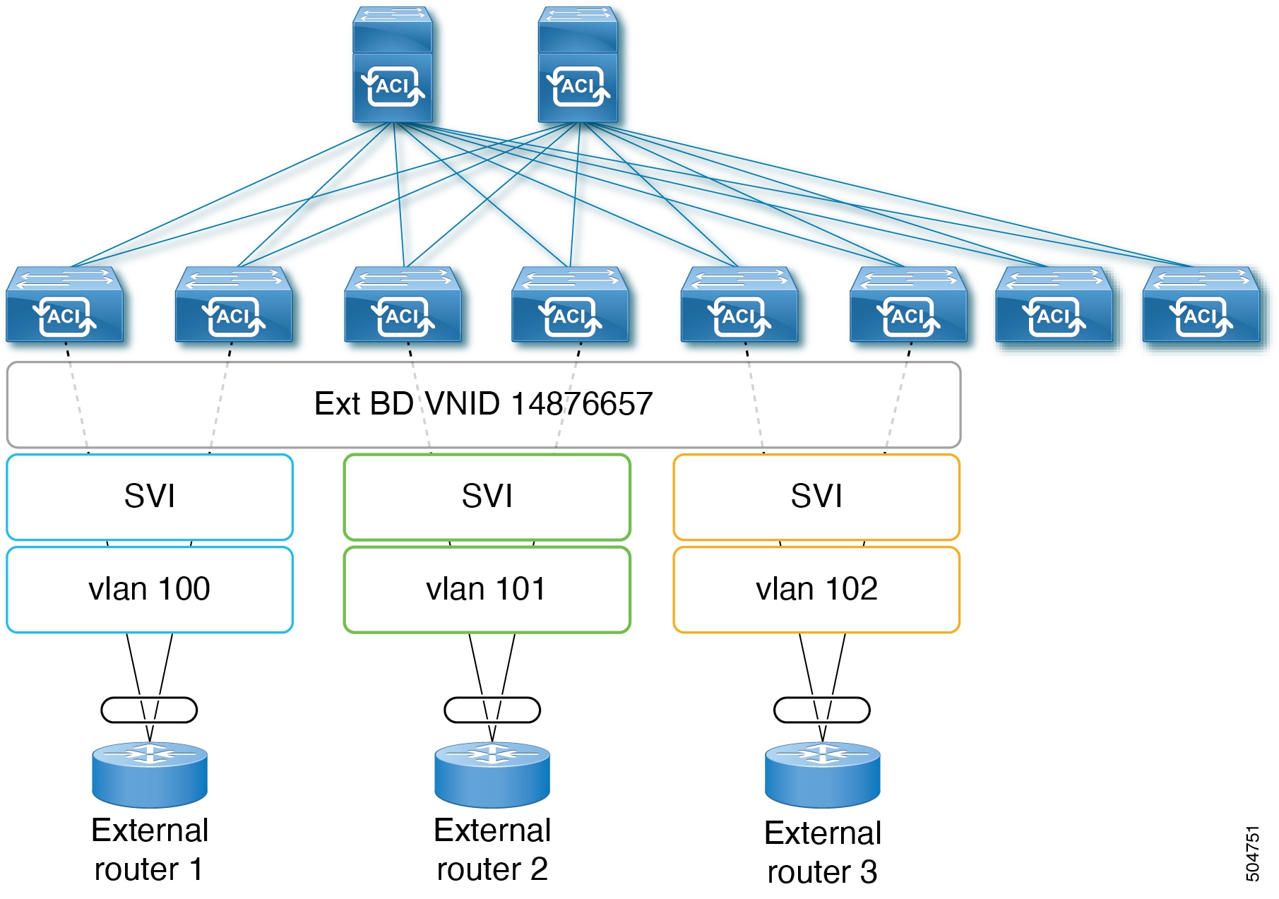
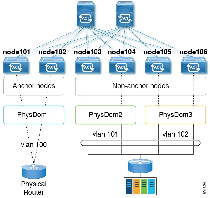
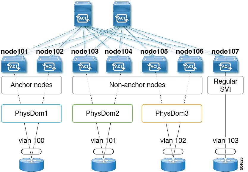
Cisco ACI Release 5.2(3) added support for configuring a single external bridge that can be configured with different encapsulation VLANs on different leaf switches. The multiple encapsulation support feature uses the floating SVI object to define the external bridge domain for floating L3Outs or an external bridge group profile for defining the external bridge domain for regular L3Outs. The use case for this feature may be where the same VLAN cannot be used on different leaf switches because it may already be in use.

Figure 2. Separate VNID Associated to External Bridge Domains with Different Encapsulation (pre-ACI 5.2(3) Releases)

As of Cisco ACI release 6.0(1), this feature is supported for physical domain L3Outs only, not for VMM domain L3Outs.

Single Floating SVI With Different VLAN Encapsulations on Non-Anchor Nodes

The following figure shows a configuration with a single floating SVI using multiple physical domains and different VLAN encapsulations.

Figure 3. Single Floating SVI using Multiple Physical Domains and Different VLAN Encapsulations

For this use case:

  • Leaf switches node101 and node102 are the anchor nodes, and leaf switches node103, node104, node105, and node106 are the non-anchor nodes for floating SVI vlif-100.

  • The following leaf switches needs to use the same VLAN encapsulation because they are vPC pair:

    • node101 and node102

  • The use of different physical domains is required to provision different VLAN encapsulations for the same floating SVI on different sets of leaf switches. It’s because the VLANs are provisioned based on physical domains configured on path attributes for different sets of leaf switches. In this example, three physical domains are required:

    • physDom1: VLAN 100 for leaf node 101 and node 102.

    • physDom2: VLAN 101 for leaf node 103 and node 104.

    • physDom3: VLAN 102 for leaf node 105 and node 106.

To configure the use case shown above:

  1. Create a physical domain physDom1 with an attachable entity profile (AEP) anchor-nodes associated with leaf switches node101 and node102 as anchor nodes.

  2. Create additional physical domains for each of the required access encapsulation sets.

  3. Create a physical domain physDom2 with an AEP floating-set1 associated with leaf switches node103 and node104.

  4. Create a physical domain physDom3 with an AEP floating-set2 associated with leaf switches node105 and node106.

  5. Create a floating SVI vlif-100 with encapsulation vlan100 with node101 as the anchor node.

  6. Create a floating SVI vlif-100 with encapsulation vlan100 with node102 as the anchor node.

  7. Add physical domain path attributes to the floating SVI:

    • Physical domain physDom2 added with access encapsulation vlan101

    • Physical domain physDom3 added with access encapsulation vlan102


    Note


    Anchor leaf nodes will use the VLAN encapsulation configured for the floating SVI. Thus, anchor leaf nodes using physical domain physDom1 vlan100 that is the same as the floating SVI vlif-100.


The following figure shows a configuration where a floating SVI and a regular SVI are grouped together with different VLAN encapsulations. For regular L3Outs, a new object called external bridge group profile needs to be configured to group SVIs under an L3Out with different VLANs together to be part of the same external bridge domain.

Figure 4. Different VLAN encapsulations with Floating and Regular SVIs

For this use case:

  • Leaf switches node101 and node102 are the anchor nodes, and leaf switches node103, node104, node105, and node106 are the non-anchor nodes, for floating SVI vlif-100

  • Leaf switch node107 has regular SVI vlif-103

  • The following leaf switch pairs need to use the same VLAN encapsulation because they are VPC pairs:

    • node101 and node102

    • node103 and node104

    • node105 and node106

  • The use of different physical domains is required to provision different VLAN encapsulations for the same floating SVI on different sets of leaf switches. It’s because the VLANs are provisioned based on physical domains configured on path attribute for different sets of leaf switches. In this example, three physical domains are required:

    • physDom1: VLAN 100 for leaf node 101 and node 102.

    • physDom2: VLAN 101 for leaf node 103 and node 104.

    • physDom3: VLAN 102 for leaf node 105 and node 106.

    • For regular SVI with VLAN 103, this consideration is not applicable.

To configure the use case shown above, where you are grouping multiple SVIs into an external bridge domain:

  1. Create the floating SVI vlif-100 with encapsulation vlan100.

  2. Configure anchor leaf switches node101 and node102 using the VLAN encapsulation vlan100 (the same VLAN encapsulation as the vlif-100 anchor encapsulation).

  3. Configure the remaining leaf switches with a different VLAN encapsulation:

    • Configure leaf switches node103 and node104 with access encapsulation vlan101

    • Configure leaf switches node105 and node106 with access encapsulation vlan102

  4. Create the regular SVI svi-103 with encapsulation vlan103 on leaf switch node107.

  5. Group the floating SVI vlif-100 and the regular SVI svi-103 together to behave as part of a single external bridge domain:

    1. Create an external bridge group profile.

      The external bridge group profile is represented by the new MO l3extBdProfile

    2. Provide a unique name string for the external bridge group profile.

    3. Associate each of the regular and floating SVIs that need to be grouped together to the same external bridge domain.

    4. Associate the SVIs to the external bridge group profile.

      Two new MOs are available for this association: l3extBdProfileContand l3extRsBdProfile.

Guidelines and Limitations of Multiple Encapsulation for L3Outs with SVI

  • This feature is supported for physical domain L3Outs only, not for VMM domain L3Outs.

  • The use case for this feature is for connectivity to external routers. Layer 2 loops are supposed to be blocked by the external device/hypervisor. Loops may occur if this feature is used with external switches that rely on spanning tree protocol to prevent loops.

  • Configuring an external bridge group profile under an SVI or floating SVI causes the VLAN to be reprogrammed on the leaf switches, which causes traffic disruption.

  • Create a separate physical domain and AEP for each of the different access encapsulations that you want to deploy.

  • The nodes that are part of each of these AEPs should be non-overlapping. For example, AEP1 and AEP2 cannot be used on the same leaf node if VLAN 101 and VLAN102 are used for the same floating SVI.

    • AEP1 has physical domain1 with VLAN 101

    • AEP2 has physical domain1 with VLAN 102

  • SVIs in the same external bridge group with different VLAN encapsulations cannot be programmed on the same leaf. For example, SVI1 and SVI2 cannot be programmed on the same leaf node.

    • SVI1 on node101 with VLAN 101

    • SVI2 on node101 with VLAN 102

  • The anchor nodes and the VPC pairs of these anchor nodes should be part of a single physical domain and AEP.

  • Path Attribute configuration (l3extRsDynPathAtt) at floating SVI has the following considerations:

    • Physical domain for the VLAN used on anchor leaf nodes: Access Encap needs to be blank

    • Physical domains for other VLANs: the specific VLAN needs to be configured at Access Encap

  • Do not configure the same physical domain with different VLAN encapsulation under the same floating SVI or external bridge profile group.

  • The SVI Encap Scope must be set to Local. VRF Encap scope is not supported.

  • If you downgrade from release Cisco Application Centric Infrastructure (ACI) 5.2(3) to a previous release where multiple VLAN encapsulation for L3Outs with SVI is not supported, the following actions will be performed on the L3Out that was configured with multiple encapsulations and/or the external bridge group profile:

    • The new allocator used for the multiple encapsulation support (l3extBdProfileEncapAllocator) will be deleted

    • All external bridge group profiles (new l3extBdProfile MOs) will be deleted

    • All new l3extBdProfileCont MOs will be deleted

    • All new l3extRsBdProfile MOs will be deleted

    • All L3Out dynamic attachments (l3extRsDynPathAtt MOs) with explicit encapsulation configurations will be deleted

Configuring Multiple Encapsulation for L3Outs With SVI and Floating SVIs Using the GUI

Multiple Encapsulation with SVI is supported on both regular and floating SVIs but uses different configuration. Floating SVIs support mapping the floating SVI to a physical domain using a Path Attribute settings under the floating SVI. To use multiple encapsulations with floating SVIs you would map the floating SVI to different domains each with a different VLAN encapsulation. The figure below illustrates an example used in this section.

Figure 5. Floating SVI configured with multiple encapsulations using different domains

Regular SVIs do not support automatic configuration of the SVI using a physical domain. With regular SVIs you must create a separate SVI on each leaf node or leaf node pair where the SVI needs to be deployed. Support for multiple encapsulations with regular SVIs is done by configuring multiple SVIs under the L3Out, each with different encapsulations, and then grouping all SVIs using a bridge group. This section will cover the configuration steps for both the floating and regular SVIs.

Figure 6. Regular SVI configured with multiple encapsulations using Bridge Groups

Creating a Floating SVI

Procedure


Step 1

To create a floating SVI:

  1. Navigate to Tenants> tenant-name> Networking> L3Outs> L3Out name> Logical Node Profile>log-node-profile-name>Logical Interface Profile>log-int-profile-name.

    The General page for this logical interface profile is displayed.

  2. Click on the Floating SVI tab.

  3. Click on the + to add a floating SVI.

  4. In the Anchor Node drop-down list, select a switch node for the anchor node.

  5. In the IPv4 Primary / IPv6 Preferred Address field, enter an IPv4 or IPV6 address and mask.

  6. In the Encap field, enter a VLAN number for the anchor nodes.

  7. Click + in the Path Attributes area.

    The Create Floating Path Attributes window appears

  8. In the Domain drop-down list, select the physical domain associated to the anchor node and other nodes where the floating SVI will be deployed with the same VLAN as the anchor node.

  9. In the Floating Primary IPv4 / IPv6 Address field, enter an IP address and mask for the floating nodes.

  10. Leave the Access Encap VLAN field blank.

  11. Click OK.

  12. Click Submit.

Step 2

Add additional path attributes to floating SVI for nodes that will use a different VLAN encapsulation.

  1. Navigate to Tenants > tenant-name > Networking > L3Outs > L3Out-name > Logical Node Profile > log-node-profile-name > Logical Interface Profile > log-int-profile-name.

    The General page for this logical interface profile is displayed.

  2. Click on the Floating SVI tab.

    A page showing the already-configured floating switch virtual interfaces is displayed.
  3. Double-click on the floating switch virtual interface where you want to specify the separate encapsulation.

  4. Click + in the Path Attributes area.

    The Create Floating Path Attributes window appears.

  5. In the Domain drop-down list, select the physical domain associated to nodes that will use different encapsulation.

  6. In the Floating Primary IPv4/IPv6 Address field, enter an IP address and mask for the floating nodes.

  7. In the Access Encap field, enter the VLAN id that will be used by the switches associated with this domain.

  8. Click OK.

  9. Click Submit.


Procedure for Multiple Encapsulations With Regular SVIs

Procedure


Step 1

To create an external bridge group that will be used for SVI grouping:

  1. Navigate to Tenants> tenant-name > Policies > Protocol > External Bridge Group Profiles.

  2. Right click on External Bridge Group Profiles and choose Create External Bridge Group Profile.

  3. Enter a name for the external bridge group profile, then click Submit.

    The page showing the already-configured external bridge group profiles is updated with the new external bridge group profile.

Step 2

To associate a regular SVI with the external bridge group profile:

  1. Navigate to Tenants>tenant-name>Networking>L3Outs>L3Out-name> Logical Node Profile>log-node-profile-name>Logical Interface Profile>log-int-profile-name.

    The General page for this logical interface profile is displayed.

  2. Click on the SVI tab.

    A page showing the already-configured floating switch virtual interfaces is displayed.

  3. Double-click on the switch virtual interface that you want to associate with the external bridge group profile.

    General information for this switch virtual interface is displayed.

  4. In the External Bridge Group Profile field, select the external bridge group profile that you want to associate with this switch virtual interface.

  5. Click Submit.

Step 3

To associate another regular SVI under the same L3Out using a different encapsulation to the same bridge:

  1. Navigate to Tenants>tenant-name>Networking>L3Outs>L3Out-name> Logical Node Profile>log-node-profile-name>Logical Interface Profile>log-int-profile-name.

    The General page for this logical interface profile is displayed.

  2. Click on the SVI tab.

    A page showing the already-configured switch virtual interfaces is displayed.

  3. Double-click on the switch virtual interface that you want to associate with the external bridge group profile.

    General information for this switch virtual interface is displayed.

  4. In the External Bridge Group Profile field, select the external bridge group profile that you want to associate with this switch virtual interface.

  5. Click Submit.


Procedure for Multiple Encapsulations With Both Floating and Regular SVIs

Procedure


Step 1

To create an external bridge group profile that will be used for SVI grouping:

  1. Navigate to Tenants>tenant-name>Policies>Protocol> External Bridge Group Profiles.

    A page showing the already-configured external bridge group profiles is displayed.

  2. Right-click on External Bridge Group and choose Create External Bridge Group Profile.

    The Create External Bridge Group Profile page is displayed.

  3. Enter a name for the external bridge group profile, then click Submit.

    The page showing the already-configured external bridge group profiles is updated with the new external bridge group profile.

Step 2

To associate a floating SVI with the external bridge group profile:

  1. Navigate to Tenants>tenant-name>Networking>L3Outs>L3Out-name>Logical Node Profile>log-node-profile-name>Logical Interface Profile>log-int-profile-name.

    The General page for this logical interface profile is displayed.

  2. Click on the Floating SVI tab.

    A page showing the already-configured switch virtual interfaces is displayed.

  3. Double-click on the switch virtual interface that you want to associate with the external bridge group profile.

    General information for this switch virtual interface is displayed.

  4. In the External Bridge Group Profile field, select the external bridge group profile that you want to associate with this switch virtual interface.

  5. Click Submit.

Step 3

To associate a regular SVI under with the external bridge group profile:

  1. Navigate to Tenants>tenant-name>Networking>L3Outs>L3Out-name>Logical Node Profile>log-node-profile-name>Logical Interface Profile>log-int-profile-name.

    The General page for this logical interface profile is displayed.

  2. Click on the SVI tab.

    A page showing the already-configured switch virtual interfaces is displayed.

  3. Double-click on the switch virtual interface that you want to associate with the external bridge group profile.

    General information for this switch virtual interface is displayed.

  4. In the External Bridge Group Profile field, select the external bridge group profile that you want to associate with this switch virtual interface.

  5. Click Submit.

Step 4

To specify the separate encapsulation for non-anchor (floating) nodes:

  1. Navigate to Tenants>tenant-name>Networking>L3Outs>L3Out-name>Logical Node Profile>log-node-profile-name>Logical Interface Profile>log-int-profile-name.

    The General page for this logical interface profile is displayed.

  2. Click on the Floating SVI tab.

    A page showing the already-configured floating switch virtual interfaces is displayed.

  3. Double-click on the floating switch virtual interface where you want to specify the separate encapsulation.

    General information for this floating switch virtual interface is displayed.

  4. Click + in the Path Attributes area.

    The Create Floating Path Attributes window appears.

  5. In the Access Encap field, enter the access encapsulation for the non-anchor (floating) nodes.

  6. Click Submit.

    You are returned to the Floating SVI page.

  7. Click Submit.


Configuring Multiple Encapsulation for L3Outs With SVI Using the CLI

Procedure


Step 1

Log into your Cisco Application Policy Infrastructure Controller (APIC) through the CLI, then go into configuration mode and tenant configuration mode.


apic1#
apic1# configuration
apic1(config)# tenant <tenant-name>
apic1(config-tenant)#

Step 2

Enter the following commands to create an external bridge profile that will be used for SVI grouping.


apic1(config-tenant)# external-bridge-profile <bridge-profile-name>
apic1(config-tenant-external-bridge-profile)# ? 

Step 3

Enter the following commands to associate a floating SVI with the external bridge group profile.


apic1(config)# leaf <leaf-ID>
apic1(config-leaf)# virtual-interface-profile <ipv4/ipv6> vlan <vlan-num> tenant <tenant-name> vrf <VRF-name> l3out <L3Out-name>
apic1(virtual-interface-profile)# ip address <IP-address>
apic1(virtual-interface-profile)#  physical-domain <phy-dom-name> floating-addr <IP-address>
apic1(physical-domain)# vlan <vlan-num>
apic1(physical-domain)# exit
apic1(config-tenant)# external-bridge-profile <bridge-profile-name>
apic1(config-tenant-external-bridge-profile)#

Step 4

Enter the following commands to associate a regular SVI with the external bridge group profile.


apic1(config)# leaf <leaf-ID>
apic1(config-leaf)# interface vlan <vlan-num>
apic1(config-leaf-if)# vrf member tenant <tenant-name> vrf <VRF-name>
apic1(config-leaf-if)# ip address <IP-address>
apic1(config-leaf-if)# external-bridge-profile <bridge-profile-name>


Configuring Multiple Encapsulation for L3Outs With SVI Using the REST API

Procedure


Step 1

Enter a post such as the following example to create an external bridge profile that will be used for SVI grouping.


<fvTenant name="t1" dn="uni/tn-t1" >
    <l3extBdProfile name="bd100" status=""/>
</fvTenant>

Step 2

Enter a post such as the following example to associate a floating SVI with the external bridge group profile.


<fvTenant name="t1">
    <l3extOut name="l1">
        <l3extLNodeP name="n1">
            <l3extLIfP name="i1">
                <l3extVirtualLIfP addr="10.1.0.1/24" 
                    encap="vlan-100" 
                    nodeDn="topology/pod-1/node-101"  
                    ifInstT="ext-svi">
                    <l3extBdProfileCont>
                        <l3extRsBdProfile tDn="uni/tn-t1/bdprofile-bd100"/>
                    </l3extBdProfileCont>
                </l3extVirtualLIfP>
            </l3extLIfP>
    </l3extOut>
</fvTenant>

Step 3

Enter a post such as the following example to associate a regular SVI with the external bridge group profile.


<fvTenant name="t1">
    <l3extOut name="l1">
        <l3extLNodeP name="n1">
            <l3extLIfP name="i1">
                <l3extRsPathL3OutAtt encap="vlan-108" 
                    tDn="topology/pod-1/paths-108/pathep-[eth1/10]" 
                    ifInstT="ext-svi">
                    <l3extBdProfileCont>
                        <l3extRsBdProfile tDn="uni/tn-t1/bdprofile-bd100" status=""/
                    </l3extBdProfileCont>
                </l3extRsPathL3OutAtt>
            </l3extLIfP>
        </l3extLNodeP>
    </l3extOut>
</fvTenant>

Step 4

Enter a post such as the following example to specify the separate encapsulation for floating nodes.


<fvTenant name="t1">
    <l3extOut name="l1">
        <l3extLNodeP name="n1">
            <l3extLIfP name="i1">
                <l3extVirtualLIfP addr="10.1.0.1/24" 
                    encap="vlan-100" 
                    nodeDn="topology/pod-1/node-101"  
                    ifInstT="ext-svi">
                    <l3extRsDynPathAtt floatingAddr="10.1.0.100/24"
                        encap="vlan-104" 
                        tDn="uni/phys-phyDom"/>
                </l3extVirtualLIfP>
            </l3extLIfP>
    </l3extOut>
</fvTenant>