- Using the Cisco Modeling Labs Client Overview
- Navigating Within the Cisco Modeling Labs Client
- Cisco Modeling Labs Client Components
Using the Cisco
Modeling Labs Client
Using the Cisco Modeling Labs Client Overview
The Cisco Modeling Labs client is a cross-platform, point-and-click GUI that simplifies topology creation and initial device configurations and permits access to the Cisco Modeling Labs server. You can interact directly with your running simulations from this GUI. Additionally, the Cisco Modeling Labs client provides the functionality to generate default router configurations before simulating your topology.
This chapter introduces the main areas and capabilities of the Cisco Modeling Labs client.
Navigating Within the Cisco Modeling Labs Client
This section describes the functionality of the Cisco Modeling Labs client, which comprises a workbench containing a menu bar, a toolbar, multiple editors, multiple perspectives, and multiple views.
- Workbench: Refers to the
Cisco Modeling Labs client desktop environment. Each time the workbench is
exited, it is automatically saved, including all the open perspectives, views,
and editors. When the workbench is reopened, it appears exactly as it was when
last closed.
Figure 1. Cisco Modeling Labs Workbench 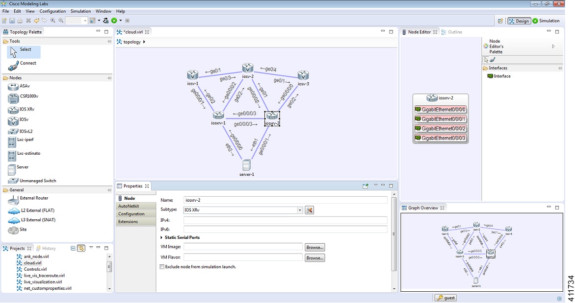
- Menu Bar: References all
the actions that can be performed when using the Cisco Modeling Labs client.
Figure 2. Menu Bar 
- Toolbar: Contains a set of
icons representing commands. The toolbar provides shortcuts to actions that are
used most often from the menu bar.
Figure 3. Toolbar 
- Cisco Modeling Labs Client
Perspectives: Identifies the
Design and
Simulation
perspectives, each of which is associated with an initial set of views and
editors in your workbench.
Figure 4. Perspectives 
-
From the Design perspective, you can design your network topology, build the node configurations, and check routing protocols. The Design perspective is the default perspective if you are launching the Cisco Modeling Labs client for the first time.
-
From the Simulation perspective, you can enable devices and modify configurations to run the simulations. When the nodes in your topology are fully initialized, you can connect to the consoles as you would connect to a router console.
-
- Cisco Modeling Labs Client Editors: Provides alternative components within the Cisco Modeling Labs client from which you can create and edit topologies. Two editors are provided: Node Editor and Topology Editor.
-
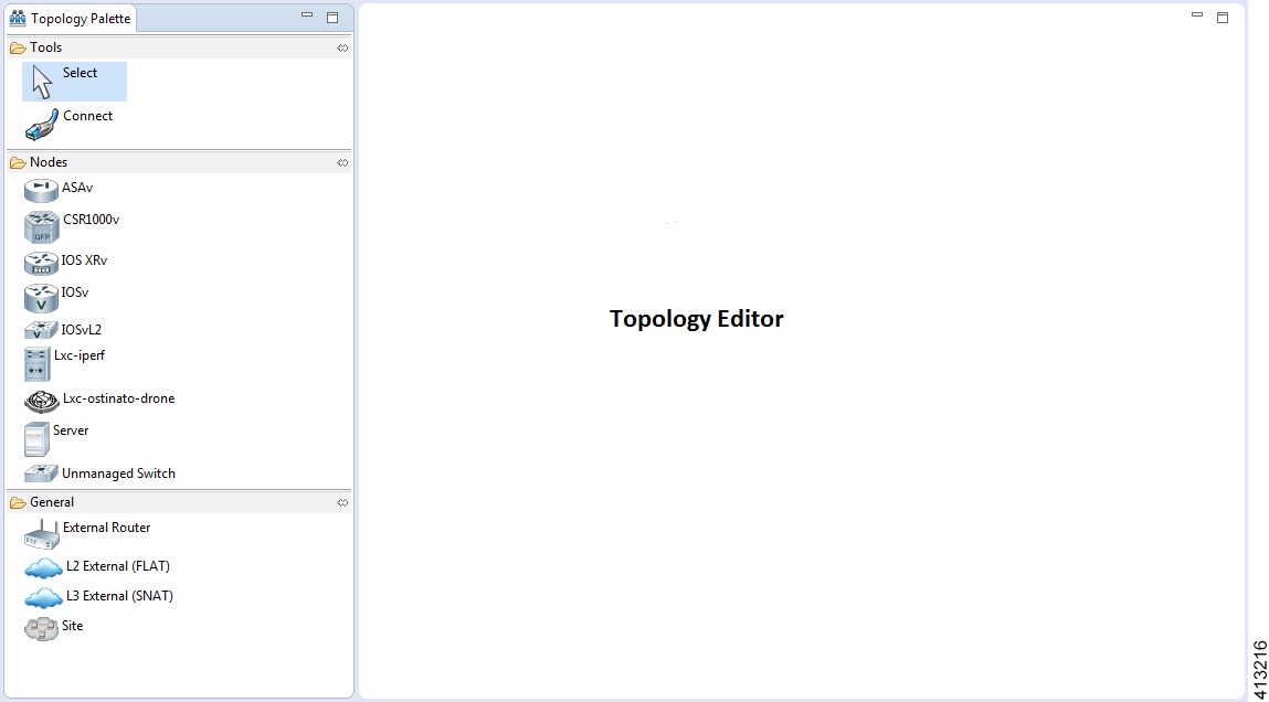
The Topology Editor comprises the Topology Palette view Figure 6. Topology Palette View and the canvas.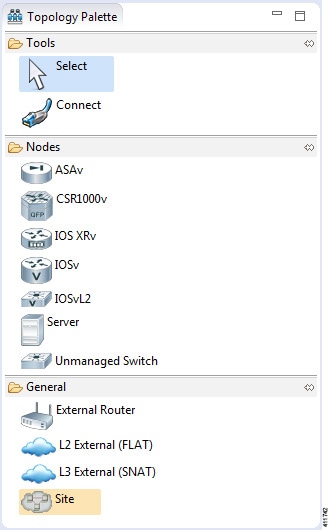
Figure 7. Canvas 
- Cisco Modeling Labs Client
Views: Provides alternative presentations of your topology and methods for
navigating the information in your workbench.
Figure 8. Views 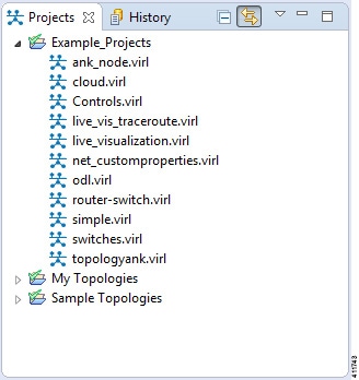
- Cisco Modeling Labs Client Layout: Enables you to personalize your workbench, allowing you to rearrange, resize, reset, and move between views.
Menu Bar
The menu bar provides access to the complete list of actions that are possible in the Cisco Modeling Labs client.
| Menu | Action(s) |
|---|---|
| File | Enables you to perform actions on a topology .virl file, set
preferences for resources, and exit the Cisco Modeling Labs client.
|
| Edit | Enables you to manipulate resources on the canvas.
|
| View | Enables you to manipulate the Cisco Modeling Labs client.
|
| Configuration | Enables you to generate node configurations. |
| Simulation | Enables you to start and stop simulations. |
| Window | Enables you to manage perspectives in the Cisco Modeling Labs client. |
| Help | Displays the help topics for using the Cisco Modeling Labs
client in a separate browser window.
|
Importing a Topology File
Exporting a Topology File
Generate Problem Reports
The Cisco Modeling Labs client provides functionality that allows you to generate problem reports for any problems encountered in your topology. It is accessible from the menu bar under .
While all options are preselected, you can individually select the information you want to include in the report.
 Note | When generating a problem report for your topology, you must have the topology containing the problem open on the canvas. |
| Option | Description |
|---|---|
| Log File | User interface .log file from the user's workspace. |
| Consoles' Content | Current content from the Console view messages. These are messages from the server in response to AutoNetkit and simulation launch actions. |
| Topology Editor Contents | Contents of the currently open topology file in the Topology Editor canvas. |
| Screenshot of the User Interface | Screenshot showing the state of the user interface when the problem occurred. |
| Web Services Setting | Report of the web services details and errors. |
| Additional Information | Any additional information that users can provide to describe the problem. |
The generated problem report is saved to a .zip file, where you can check the contents before sending it to Cisco TAC for investigation.
Toolbar
The toolbar is a compilation of icons representing commonly used actions. The toolbar is arranged below the menu bar and offers the same actions as the menu bar in a single click. The following table outlines the actions that can be performed using the Cisco Modeling Labs client toolbar.
| Icon | Function | Description |
|---|---|---|
|
|
New Topology File | Creates a new topology file. A topology file is a .virl file where the network arrangement is designed. |
|
|
Save | Saves the current topology. |
|
|
Prints the current topology. | |
|
|
Delete | Deletes the currently selected element within the topology. |
|
|
Undo | Undoes the most recent action. |
|
|
Redo | Redoes the most recent undone action. |
|
|
Zoom In | Enlarges the topology view on the canvas. |
|
|
Zoom Out | Decreases the topology view on the canvas. |
|
|
Show Topology Labels | Displays either IPv4 or IPv6 loopback addresses configured manually or by AutoNetkit for the topology on the canvas. |
|
|
Build Initial Configurations | Generates initial node configurations for the topology. |
|
|
Launch Simulation | Launches a simulation indefinitely or for a user-specified time period. |
|
|
Stop Simulations | Stops all running simulation(s). |
Cisco Modeling Labs Client Components
The three main components of the Cisco Modeling Labs client are described in the following sections:
- Cisco Modeling Labs Client Editors
- Cisco Modeling Labs Client Perspectives
- Cisco Modeling Labs Client Views
Cisco Modeling Labs Client Editors
Editors are visual components within the Cisco Modeling Labs client. Currently, two editors are available:
- Topology Editor: Shows the entire topology (or sites). The Topology Editor comprises the Palette view and the canvas.
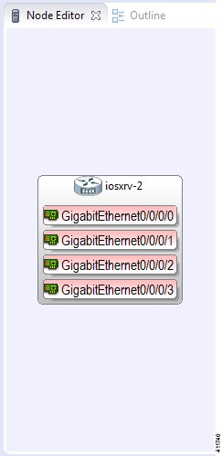
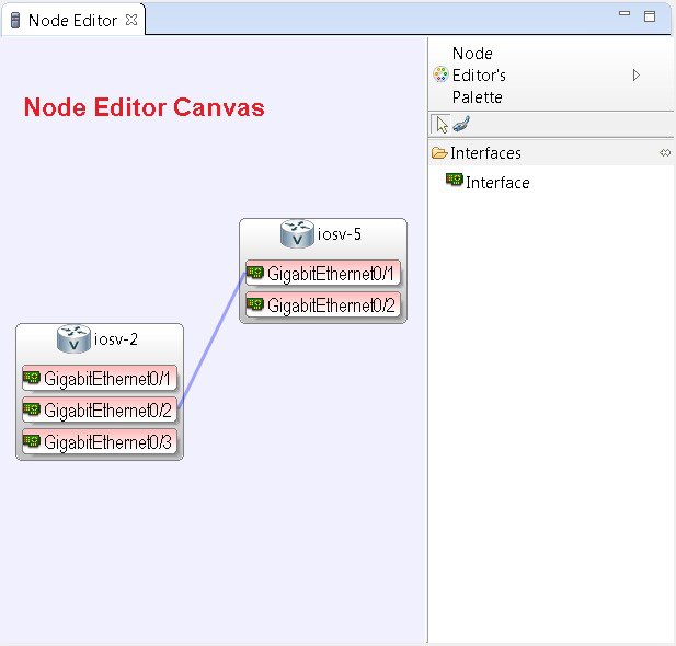
- Node Editor: Shows the interface details for the currently selected elements in the Topology Editor.
Note | Selecting a connection in the Topology Editor shows the details of both the endpoints in the Node Editor. |
Topology Editor
The Topology Editor allows you to:
- Add, move, group, rename, delete nodes, and sites on the canvas, or change the properties.
- Create or remove connections between nodes.
- Use GPS coordinates to map your topology to precise geographic locations.
Node Editor
The Node Editor allows you to:
- Add interfaces to a node.
- Add connections to the interfaces on a node.
- View nodes, their connections, and all the interfaces on the nodes.
- Specify which interface the connection connects to on each node.
- Update properties for interfaces.
Cisco Modeling Labs Client Perspectives
A perspective defines the initial set and layout of views and editors in the workbench. The Cisco Modeling Labs client provides two perspectives. However, you can customize your own user-defined perspectives for use, which can be saved or deleted as needed.
- Design: Allows you to create and design your topologies, for example, adding devices and defining interfaces and adding connections to devices within your network. If you are using the Cisco Modeling Labs client for the first time, the Design perspective opens by default.
- Simulation: Allows you to simulate running configurations that are generated from Cisco IOSv versions.
Note | The Design and Simulation perspectives that are built into the Cisco Modeling Labs client cannot be deleted. |
One or more perspectives can exist in a single workspace. If multiple perspectives are opened at the same time, you can choose whether to layer them or open them in a separate workspace.
Working with Perspectives
You can manage the various perspectives defined in the workbench by choosing .
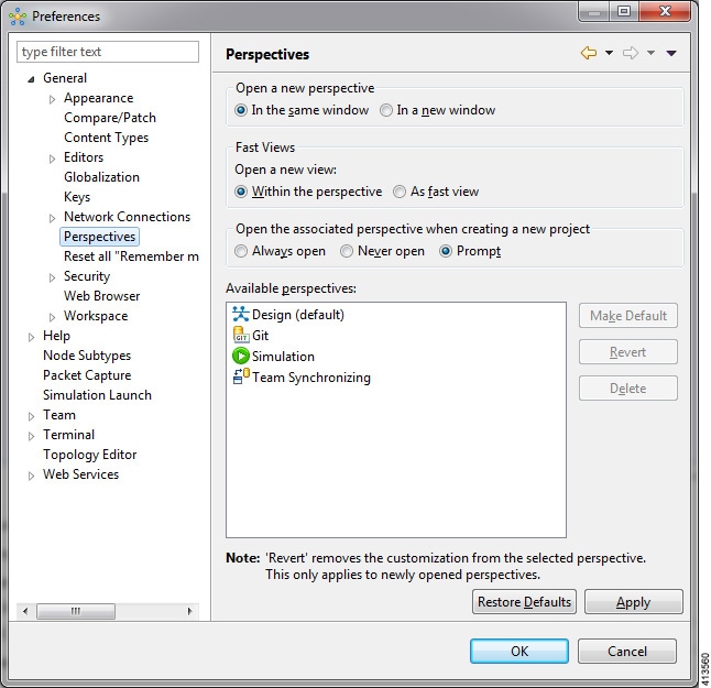
The following table describes the Perspectives options:
| Option | Description |
|---|---|
| Open a new perspective | Defines whether a new perspective opens in the current workbench or opens in a new window. By default, a new perspective opens in the current workbench. |
| Open a new view | Defines whether a new view opens within the current perspective or opens docked beside the current perspective (fast view). By default, a new view opens within the current perspective. |
| New project options | Defines perspective behavior when a new project is created. By default, a new project opens the perspective in the same workbench. |
The following table describes the Available perspectives options:
| Option | Description |
|---|---|
| Make Default | Sets the selected perspective as the default perspective. |
| Revert | Resets the definition of the selected perspective to the default configuration. This option is only applicable to system-defined perspectives. |
| Delete | Deletes the selected perspective. This option is only applicable to user-defined perspectives. (System-defined perspectives cannot be deleted.) |
Customize Perspectives
Cisco Modeling Labs provides two perspectives for use in the workspace: the Design perspective and the Simulation perspective. These perspectives display various views and settings that cannot be changed, nor can they be deleted from the Cisco Modeling Labs client. You can, however, customize additional Design and Simulation perspectives for your specific needs.
From the View menu, you can open additional views and arrange them in your perspective. The views can be arranged by dragging them around the workspace. When finished, you can save the perspective.
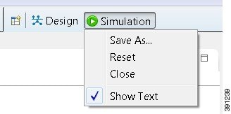
Note | Right-click the applicable perspective tab to open the context menu, and then click Show Text. The Design perspective and the Simulation perspective buttons will be displayed as text labels instead of icons only. |
| Step 1 | Open the
Design
perspective or
Simulation
perspective in your workspace.
 Use this as an initial template from which to create a customized perspective. |
| Step 2 | To add new views, choose and the Show View dialog box is displayed listing all views for use. Views already in use are shown as dimmed in the list. |
| Step 3 | To add node information, double-click a node to add a Node Editor in the perspective. |
| Step 4 | Click and drag the views and Node Editors to different positions within the workspace. For example, you can move each node's Console view so they are either side by side or stacked in tabs. |
| Step 5 | When you are finished arranging the workspace, right-click the applicable perspective button, and then click Save As. You are prompted to name the new perspective. |
| Step 6 | Enter a name for the perspective and click OK. |
Design Perspective
The Design perspective allows you to create and design your topologies. By default, the Design perspective incorporates the components listed here because they are the most widely used. However, you can customize a Design perspective to include a different set of components.
-
Palette view: Provides the node types, connection types, and sites used to design a topology.
-
Projects view: Lists topology projects, subfolders, and files defined from the workbench.
-
History view: Lists changes made to a file based on date and time stamp.
-
Properties view: Identifies node and interface properties.
-
Node Editor: Identifies nodes, node connections, and node interfaces.
-
Topology Editor: Develops a network topology.
-
Graph Overview: Provides methods for viewing a network topology.
To customize a new Design perspective, choose the desired components from the View menu (for example, ), and then drag that component view to the desired location within the workbench. When you are done adding components to the workbench and the component views are laid out as desired, right-click the Design perspective button, select Save As, and enter a name for the new Design perspective.
From the Design perspective, right-click the Design icon. This displays the following menu options:
| Operation | Description | ||
|---|---|---|---|
| Save As | Saves the customized workbench layout, views, and editors as a new Design perspective. | ||
| Reset | Resets the current perspective to display the workbench design
that was used when the workbench was first opened.
|
||
| Close | Closes the current perspective. You can reopen it using the Open Perspective tool, which is located at the upper right corner of the window. | ||
| Show Text | When selected, shows perspective names in the toolbar instead
of icons.
When deselected, shows perspective icons in the toolbar instead of names. |
Simulation Perspective
The Simulation perspective opens after you launch a simulation; you are prompted to switch to the Simulation perspective. Switching to the Simulation perspective means that you can now connect to your running nodes in the Simulations view. By default, it incorporates the Topology Editor, Projects view, Simulations view, Console view, and Terminal view.
From the Simulation perspective, right-click the Simulation icon. This displays the following menu options:
| Operation | Description | ||
|---|---|---|---|
| Save As | Saves the current perspective. | ||
| Reset | Resets the current perspective to its original configuration
(when the workbench opened initially).
|
||
| Close | Closes the current perspective. (Reopen it using the Open Perspective tool.) | ||
| Show Text | When selected, shows perspective names in the toolbar instead
of icons.
When deselected, shows perspective icons in the toolbar instead of names. |
Cisco Modeling Labs Client Views
Views provide alternative methods for presenting topology information and navigating within your workbench. You can drag the view windows and position them anywhere within the workbench. Some views have their own toolbars, and some of the tools on these toolbars are specific to the views being presented.
The most commonly used views within the Cisco Modeling Labs client are listed in the following table:
| View Name | Perspective Where Used | Description |
|---|---|---|
| Console view | Design and Simulation | Design—Displays messages from AutoNetkit when it is used to
generate router configurations.
Simulation—Displays message streams from the Cisco Modeling Labs server after a simulation is launched. For more information, see Console View. |
| Graph Overview | Design | Provides you with the ability to view a scaled-down version of
your entire topology.
For more information, see Graph Overview. |
| History view | Design | Provides a history of changes made to a file and enables you to select a previous file version from the list. For more information, see History View. |
| Topology Palette view | Design | Allows you to add devices and interface connections to your
topology.
For more information, see Topology Palette View. |
| Problems view | Design | Displays errors, warnings, and other information that was
detected within the
Topology
Editor.
For more information, see Problems View. |
| Projects view | Design and Simulation | Provides a hierarchical view of topology projects, folders, and
topologies in the workbench.
For more information, see Projects View. |
| Properties view | Design | Displays names and properties of nodes and interfaces.
For more information, see Properties View. |
| Search view | Design |
Displays the results of a search, which can be based on text strings, regular expressions, patterns, whole words, and case-sensitive characters. For more information, see Search View. |
| Simulations view | Simulation | Displays information on all running simulations.
For more information, see Simulations View. |
| Terminal view | Simulation | Displays console information when you use Telnet or SSH to
connect to a node.
For more information, see Terminal View. |
- Console View
- Graph Overview
- History View
- Topology Palette View
- Problems View
- Projects View
- Properties View
- Search View
- Simulations View
- Terminal View
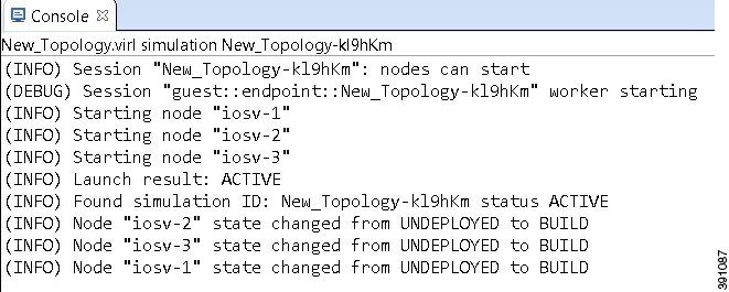
Console View
The Console view displays message streams from the Cisco Modeling Labs server after a simulation is launched. It also displays messages from AutoNetkit when it is used to generate router configurations.

| Icon | Function | Description |
|---|---|---|
|
|
Clear Console | Removes all the information from the Console view. |
|
|
Scroll Lock | Switches scrolling on and off. |
|
|
Pin Console | Pins the Console view to the workbench so that subsequent message streams are shown in another Console view. The pinned view remains unchanged. |
|
|
Display Selected Console | Displays the Console view for the selected simulation. |
|
|
Open Console | Opens a new Console view. |
|
|
Minimize | Reduces the size of the Console view. |
|
|
Maximize | Increases the size of the Console view. |
Note | When several simulations are running, use the toolbar button Display Selected Console to toggle between the Console views for the different simulations. |
Graph Overview
Graph Overview enables you to view a scaled-down version of your entire topology. A blue rectangle (representing an overlay) is used to indicate a portion of the topology that is currently being displayed in the Topology Editor. Using this overlay, you can easily see where the displayed portion sits in relation to the entire topology.
The Graph Overview also allows you to navigate around a large topology when it is either too large to fit into the canvas or is zoomed in and not fully displayed on the canvas.
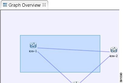
From the Graph Overview, click and drag the overlay to pan around your topology. As you drag the overlay, the corresponding content is reflected in the Topology Editor.
History View
Note | Only changes made to topology files (.virl) are retained locally; changes made to projects and folders are not. |
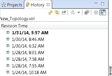
To view the changed history of a file, in the Projects view, right-click the applicable file and choose .
The History view displays a list of revision times; the most recent revision time is highlighted at the top of the list.
Note | If you have a .virl file opened in the workbench, click the History tab to view the list of changes made to the file. |

| Icon | Function | Description |
|---|---|---|
|
|
Refresh | Refreshes the contents of the view, retrieving the latest history information for a file from the system. |
|
|
Link with Editor and Selection | Toggles when the History view selection is linked to the active editor. When this option is selected, changing the active editor automatically updates the History view selection to the project, folder, and file being edited. |
|
|
Pin this History View | Pins the view to the workbench and captures a snapshot of the file history information. New requests for file history are opened in a new instance of the History view. |
|
|
Group Revisions by Date | Sorts all history items by date. Options are: |
|
|
Collapse All | Collapses all the history items listed in the hierarchical view. |
|
|
Compare Mode | Opens the compare editor for file comparison. |
Topology Palette View
The Topology Palette view allows you to add devices and interface connections to your topology. Using the Topology Palette view, you can:
- Add nodes, Layer 3 external Secure Network Address Translation (SNAT) connections, and Layer 2 external (FLAT) connections to your topologies.
- Select nodes and connections for repositioning on the canvas.
- Create connections between node interfaces.
- Group nodes into sites.
The Topology Palette view is divided into the following categories:
- Tools: Contains the
Select and
Connect tools.
The
Select tool
allows you to select nodes, Layer 3 external (SNAT) connections, and Layer 2
external (FLAT) connections on the
Topology Editor
canvas. The
Connect tool
creates connections between node interfaces.
Note
The setting affects how the nodes and connections are placed on the canvas. If you check the Revert back to the palette's default tool check box, you must click a node, connection, or other object each time you place an object on the canvas. If the Revert back to the palette's default tool check box is not checked, each time you click the canvas, an object is placed until you click the Select tool (the default palette tool). -
Nodes: Contains the node types available for use in topologies. Currently, Cisco Modeling Labs, Release 1.2 includes the following: -
Cisco Virtual IOS (IOSv) Software Release 15.6(2)T
-
Cisco IOSv Layer 2 Switch Software Release 15.2.(4.0.55) DSGS
-
Cisco IOS XRv Software Release 6.0.0 CCO
-
Linux server Ubuntu 14.04.2 LTS Cloud-init
-
Cisco ASAv Software Release 9.5.1
Note
Additional node subtypes can be installed separately. See Release Notes for Cisco Modeling Labs Release 1.2 for the most up-to-date list of supported virtual images. -
- General: Contains the different types of connection functions that are supported for nodes. Options are: You can also create sites.
The Topology Palette view toolbar contains the following tools:
| Icon | Tool | Description |
|---|---|---|
|
|
Minimize | Reduces size of Palette view. |
|
|
Maximize | Increases size of Palette view. |
Problems View
Note | By default, the Problems view displays all the errors and warnings for all the topologies in the Projects view, not just the currently open topology. From the Problems view toolbar, choose to filter only those errors and warnings that are applicable to the current project. Alternatively, you can also use the Configure Contents dialog box, which is accessible from the View Menu option, to filter warnings and errors associated with a particular topology or topology project. |
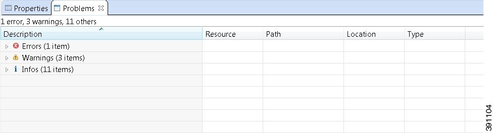
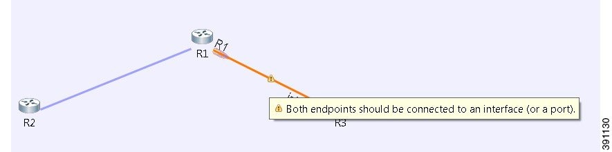
The Problems view groups errors and warnings by severity, with the most critical issues listed first.
Double-click the problem marker in the Problems view, which opens the appropriate editor in the Cisco Modeling Labs client. If the problem relates to an XML file, the XML file opens in a text editor. The problem is highlighted, allowing you to quickly identify the issue and correct it.
| Icon | Function | Description |
|---|---|---|
|
|
View Menu | The
View menu has the following options:
|
|
|
Minimize | Reduces the size of the Problems view. |
|
|
Maximize | Increases the size of the Problems view. |
The Quick Fix Option
Problems displayed in the Problems view are provided with a Quick Fix option if available. A quick fix is indicated by a light bulb icon that is visible on the marker. When this option is selected, you are presented with one or more possible fixes.
We recommend that you use Quick Fix to resolve the errors discovered unless the errors have been deliberately created for testing purposes.
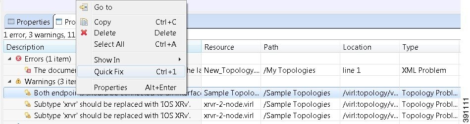
To fix a problem:
- Right-click the line containing
the problem, and select
Quick Fix.
The Quick Fix dialog box displays a list of possible solutions.
Figure 23. Quick Fix Dialog Box 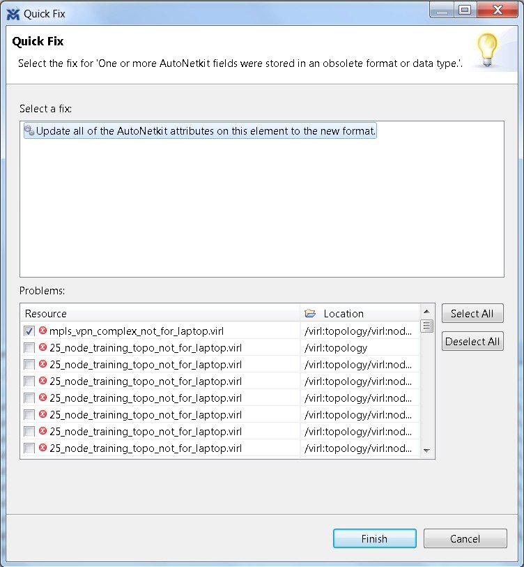
- Select a fix from the list, and then check the check box of any of the resources listed in the Problems area. You can click Select All to apply the quick fix to all the resources listed. Alternatively, you can click Deselect All to clear all selections.
- Click Finish.
Note | Once a problem has been fixed using the Quick Fix option, the action cannot be undone. |
Projects View
The Projects view provides a hierarchical view of topology projects, folders, and topologies in the workbench. From here, you can open topologies for editing or select resources for operations, such as exporting.
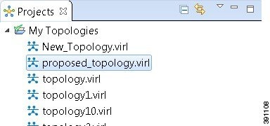
Right-click any topology in the Projects view to open a context menu. In this context menu, you can copy, move, and create new topology files, view comparison files, and so on.

| Icon | Function | Description |
|---|---|---|
|
|
Collapse All | Collapses the hierarchy of all the resources in the Projects view. |
|
|
Link with Editor | Links the Projects view with an active editor. A change to an active editor automatically updates the Projects view and allows you to toggle between the two views. |
|
|
View Menu | Provides options for customizing the content displayed in the Projects view. Options are: |
|
|
Minimize | Reduces the size of the Projects view. |
|
|
Maximize | Increases the size of the Projects view. |
The Projects view displays several icons on the toolbar:
| Icon | Name | Description |
|---|---|---|
|
|
Topology Project | Indicates an open topology project. |
|
|
Folder | Indicates an open folder. Folders are created within a topology project so that topology files can be organized into separate areas for greater accessibility. |
|
|
Topology | Indicates a topology file. |
Properties View
The Properties view displays the names and properties of nodes and interfaces. If no specific node or interface is selected, the Properties settings apply globally to all the nodes and interfaces within a topology. If a specific node or interface is selected, the Properties settings apply to only that node or interface.
| Icon | Function | Description |
|---|---|---|
|
|
Show Categories | Shows the available properties categories. |
|
|
Show Advanced Properties | Shows all advanced properties. |
|
|
Restore Default Value | Restores the default value for the property. |
|
|
Pin to Selection | Pins this properties view to the current selection. |
|
|
View Menu | Displays menu items that allow you to: |
|
|
Minimize | Reduces the size of the Properties view. |
|
|
Maximize | Increases the size of the Properties view. |
The properties in the Properties view are discussed in the following sections:
Node Properties
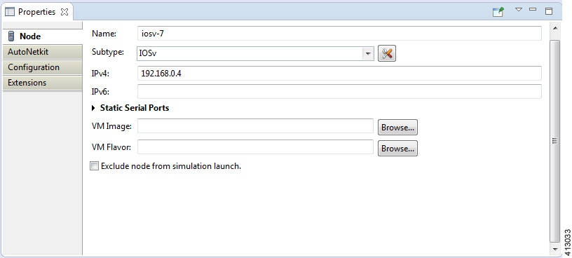
Under the Node tab, you can perform the following tasks:
| Property
|
Description
|
||
|---|---|---|---|
| Name
|
Specify a name for the node.
|
||
| Subtype
|
Specify a subtype from the list. Cisco Modeling Labs 1.2
includes the following images built into the Cisco Modeling Labs client:
|
||
| IPv4
|
Specify an IPv4 loopback address. The loopback address is added
to the router as interface loopback0. Enter a valid IP address in the correct
format.
|
||
| IPv6
|
Specify an IPv6 loopback address. The loopback address is added
to the router as interface loopback0. Enter a valid IP address in the correct
format.
|
||
| VM Image
|
Specify a VM image other than the default. Click
Browse to
choose a valid VM image from the
Select VM Image dialog box.
|
||
| VM Flavor
|
Specify a VM flavor other than the default. Click
Browse to
choose a valid VM flavor from the
Select VM Flavor dialog box.
|
The property Exclude Node from Simulation Launch is set on a per-node basis. When it is enabled for a node, the node is not launched when the simulation is launched. However, the node can later be booted and configured and automatically join a running simulation.
Note | Any preexisting configuration for a node is overwritten when you choose Build Initial Configurations from the toolbar. Uncheck this Auto-generate the configuration based on these attributes check box if you do not want the router configuration for a node updated by AutoNetkit.
|
Using the properties listed, you can perform the following tasks:
|
Property |
Fields |
Description |
||
|---|---|---|---|---|
|
General |
ASN |
Specify the autonomous system number, which is used to infer IGP and BGP. This can be any valid integer. |
||
|
IGP |
IGP |
|
||
|
|
OSPF Area |
Configure an OSPF area. The default value is 0. |
||
|
iBGP |
iBGP Role |
Configure an iBGP role from the list and use it to create an iBGP topology. Options are: The default value is Peer. | ||
|
|
RR Cluster |
Specify the RRC as a name or number. Should be an alphanumeric string. |
||
|
|
HRR Cluster |
Specify the HRR cluster. Should be an alphanumeric string. |
||
|
Custom Configuration |
Global |
|
||
|
|
Physical Interfaces |
Specify a custom configuration for the physical interfaces. |
||
|
|
Loopback Zero |
Specify a custom configuration for loopback zero. |
||
|
|
OSPF |
Specify a custom configuration for OSPF. |
||
|
|
IS-IS |
Specify a custom configuration for IS-IS. |
||
|
|
EIGRP |
Specify a custom configuration for EIGRP. |
||
|
|
RIP-V2 |
Specify a custom configuration for RIPv2. |
||
|
|
BGP |
Specify a custom configuration for BGP. |
||
|
MPLS |
VRF Name |
Specify an MPLS VPN name for VRF MPLS VPNs. |
||
|
|
LDP |
|
||
|
|
Enable MPLS TE |
Enable Cisco MPLS Traffic Engineering. Options are: The default value is False. | ||
|
External BGP |
IPv4 Address |
Specify the IPv4 address of the remote router. Enter a valid IP address in the correct format. |
||
|
|
IPv6 Address |
Specify an IPv6 address of the remote router. Enter a valid IP address in the correct format. |
||
|
|
Remote ASN |
Specify the AS number of the remote router. This is used when trying to establish a BGP connection to a remote device. The value range is 1 to 65535. |
||
|
|
MD5 Password |
Specify the MD5 password to use to secure the BGP session to the remote router. |
||
|
|
Multihop |
Enable BGP multihop. When the remote router is directly adjacent (Layer 3 adjacent), this field is set to False; otherwise it is set to True. The default value is True. |
||
|
External L2TPv3 |
Remote Loopback IPv4 Address |
Specify a remote loopback IPv4 address. |
||
|
|
Local Endpoint IPv4 Address |
Specify a local endpoint IPv4 address. |
||
|
|
Local Endpoint IPv4 Netmask |
Specify a local endpoint IPv4 netmask. |
||
|
|
PseudoWire ID |
Specify a pseudowire ID. |
||
|
GRE Tunnel |
IPv4 Tunnel Enabled |
|
||
|
|
Tunnel IPv4 Address |
Specify a tunnel IPv4 address to use, which is the IP address of the far-end node terminating the GRE tunnel itself. |
||
|
|
Tunnel IPv4 Netmask |
Specify a tunnel IPv4 netmask to use. |
||
|
|
IPv6 Tunnel Enabled |
|
||
|
|
Tunnel IPv6 Address |
Specify a tunnel IPv6 address to use, which is the IP address of the far-end node terminating the GRE tunnel itself. |
||
|
|
Tunnel IPv6 Netmask |
Specify a tunnel IPv6 netmask to use. |
||
|
ODL |
ODL Management Group |
Cisco IOS XRv devices set with the ODL Management Group attribute must be paired with an External Router entity which is configured with the matching ODL Management Group attribute along with an ODL External Server IP address. The ODL server may be running on your Cisco Modeling Labs server or another location and does not need to part of the Cisco Modeling Labs simulation itself. Connectivity between the simulation and server must be provided. |
For this release, RIP-V2 has been added as an IGP in addition to IS-IS, OSPF, and EIGRP. You can specify the IGP on a per-node basis, which takes precedence over the global IGP setting. Additionally, you can specify LDP enabled/disabled per node, which allows LDP to be enabled directly, rather than only when VRFs are specified.
Per interface you can specify a VLAN. This is specified on the destination interface and determines the VLAN a node belongs to. This is used in the Cisco IOSvL2 configuration. See Assign VLANs for more information
Under the Extensions tab, all the extensions used to generate the configuration are listed with the Key, Value, and Type attributes.
Topology Properties
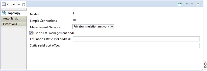
Under the Topology tab, you can perform the following tasks:
| Property | Description |
|---|---|
| Management Network | Specify the type of out-of-band (OOB) external
network access. Options are:
|
| LXC Node's Static IP Address |
Enter the IPv4 address to be assigned to the Management LXC node. This address must be in the IPv4 subnet assigned to the Flat network. |
| Static Serial Port Offset |
An optional offset value to be applied to each node's static serial port number. (New port number = node's static port number + offset value.) The new port number must be within the range 4000 - 32767. |
Note | In this instance, Nodes include node subtypes and FLAT and SNAT port groups. |
Under the AutoNetkit tab, you can perform the following tasks:
| Property
|
Fields
|
Description
|
|---|---|---|
|
General |
Enable CDP |
Enable the Cisco Discovery Protocol (CDP). Options are: The default value is False. |
|
|
Enable OnePK |
Enable the Cisco One Platform Kit (OnePK). Options are: The default value is False. |
|
Addressing |
IP Address Family |
Configure a routing session to use IPv4 address prefixes, IPv6 address prefixes, dual stack (includes both native IPv4 and IPv6), or none. Options are: |
|
|
IPv4 Infrastructure Subnet |
Specify the address to use for IPv4 infrastructure address allocations. This is the address assigned to the interface created on the router. The default value is 10.0.0.0. Enter a valid IP address in the correct format. |
|
|
IPv4 Infrastructure Prefix |
Specify the prefix to use for IPv4 infrastructure address allocations. The default value is 8. |
|
|
IPv4 Loopback Subnet |
Specify the address to use for IPv4 loopback address allocations. The default value is 192.168.0.0. Enter a valid IP address in the correct format. |
|
|
IPv4 Loopback Pool Prefix |
Specify the prefix size to use for IPv4 loopback address allocations. The default value is 22. |
|
|
IPv4 VRF Subnet |
Specify the address to use for IPv4 VRF address allocations when specifying the address range for MPLS VRF. The default value is 172.16.0.0. Enter a valid IP address in the correct format. |
|
|
IPv4 VRF Prefix |
Specify the prefix to use for IPv4 VRF address allocations. The default value is 24. |
|
|
IPv6 Infrastructure Subnet |
Specify the address to use for IPv6 infrastructure address allocations. This is the address assigned to the interface created on the router. The default value is 0:0:0:a::. Enter a valid IP address in the correct format. |
|
|
IPv6 Infrastructure Prefix |
Specify the prefix to use for IPv6 infrastructure address allocations. The default value is 64. |
|
|
IPv6 Loopback Subnet |
Specify the address to use for IPv6 loopback address allocations. The default value is 0:0:0:b::. Enter a valid IP address in the correct format. |
|
|
IPv6 Loopback Pool Prefix |
Specify the prefix size to use for IPv6 loopback address allocations. The default value is 64. |
|
|
IPv6 VRF Subnet |
Specify the address to use for IPv6 VRF address allocations when specifying the address range for MPLS VRF. The default value is 0:0:0:c::. Enter a valid IP address in the correct format. |
|
|
IPv6 VRF Prefix |
Specify the prefix to use for IPv6 VRF address allocations. The default value is 64. |
|
Routing |
Enable Routing Protocols |
Configure routing protocols (BGP and IGP). Options are:
The default value is
True.
If you specify False, there will be no router configuration for any of the routing protocols. |
|
|
IGP |
Configure the Cisco IGP. Options are: The default value is OSPF. |
|
MPLS |
Enable MPLS OAM |
Enable Cisco MPLS OAM for all routes on the topology. Options are: The default value is False. |
The following table shows the default IP address values used by Cisco Modeling Labs. You can update these values as required.
|
Viewed from |
Option |
Default Value |
Optional Value(s) |
|---|---|---|---|
|
Topology > AutoNetkit > Addressing |
IP Address Family |
v4 |
Not specified, None, v6, dual_stack |
|
|
IPv4 Infrastructure Subnet |
10.0.0.0 |
Address to use. |
|
|
IPv4 Infrastructure Prefix |
8 |
Prefix to use. |
|
|
IPv4 Loopback Subnet |
192.168.0.0 |
Address to use. |
|
|
IPv4 Loopback Pool Prefix |
22 |
Prefix to use. |
|
|
IPv4 VRF Subnet |
172.16.0.0 |
Address to use. |
|
|
IPv4 VRF Prefix |
24 |
Prefix to use. |
|
|
IPv6 Infrastructure Subnet |
0:0:0:a:: |
Address to use. |
|
|
IPv6 Infrastructure Prefix |
64 |
Prefix to use. |
|
|
IPv6 Loopback Subnet |
0:0:0:b:: |
Address to use. |
|
|
IPv6 Loopback Pool Prefix |
64 |
Prefix to use. |
|
|
IPv6 VRF Subnet |
0:0:0:c:: |
Address to use. |
|
|
IPv6 VRF Prefix |
64 |
Prefix to use. |
The following table shows the default routing protocols used by Cisco Modeling Labs. You can update these values as required.
|
Viewed from |
Option |
Default Value |
Optional Value(s) |
|---|---|---|---|
|
Topology > AutoNetkit > General |
Enable CDP |
false |
true, Not specified |
|
|
Enable OnePK |
false |
true, Not specified |
|
Topology > AutoNetkit > Routing |
Enable Routing Protocols |
true |
false, Not specified |
|
|
IGP |
OSPF |
ISIS, EIGRP, RIPv2, Not specified |
|
Topology > AutoNetkit > MPLS |
Enable MPLS OAM |
false |
true, Not specified |
|
Node > AutoNetkit > General |
ASN |
1 |
None or any valid integer |
|
Node > AutoNetkit > IGP |
IGP |
OSPF |
ISIS, EIGRP, RIPv2, Not specified |
|
OSPF Area |
0 |
None or valid OSPF area number |
|
|
Node > AutoNetkit > iBGP |
iBGP Role |
Peer |
Disabled, RRC, HRR, RR, Not specified |
|
|
RR Cluster |
No default value |
None or alphanumeric string |
|
|
HRR Cluster |
No default value |
None or alphanumeric string |
|
Node > AutoNetkit > Custom Configuration |
Global |
No default value |
Specify a custom configuration for the global stanza. |
|
|
Physical Interfaces |
No default value |
Specify a custom configuration for the physical interfaces. |
|
|
Loopback Zero |
No default value |
Specify a custom configuration for loopback zero. |
|
|
OSPF |
No default value |
Specify a custom configuration for OSPF. |
|
|
IS-IS |
No default value |
Specify a custom configuration for IS-IS. |
|
|
EIGRP |
No default value |
Specify a custom configuration for EIGRP. |
|
|
RIP-V2 |
No default value |
Specify a custom configuration for RIP-V2. |
|
|
BGP |
No default value |
Specify a custom configuration for BGP. |
|
Node > AutoNetkit > MPLS |
VRF Name |
No default value |
None or alphanumeric string |
|
|
Enable MPLS TE |
false |
true, Not specified |
|
Node > AutoNetkit > External BGP |
Multihop |
true |
false, Not specified |
|
Node > AutoNetkit > GRE Tunnel |
IPv4 Tunnel Enabled |
false |
true, Not specified |
|
|
IPv6 Tunnel Enabled |
false |
true, Not specified |
Under the Extensions tab, all the extensions used to generate the configuration are listed with the Key, Value, and Type attributes.
Interface Properties
In the Node Editor, selecting an interface on the canvas displays properties for the interface in the Properties view.
Under the Interface tab, you can perform the following tasks:
| Property | Description |
|---|---|
| Name | Specify a name for the interface. |
| IPv4 | Specify an IPv4 interface address and an IPv4 subnet prefix length. |
| IPv6 | Specify an IPv6 interface address and an IPv6 subnet prefix length. |
Note | To delete an interface from the Node Editor canvas, select the interface, right-click, and choose Delete from the context menu. |
Under the Extensions tab, all the extensions used to generate the configuration are listed with the Key, Value, and Type attributes.
Connection Properties
When you select a connection on the canvas, the properties of that connection are displayed in the Properties view.
From the Connection tab, you can associate a line style design with a connection between nodes. Line styles are visual aids that help you identify the connections used in your topology design.
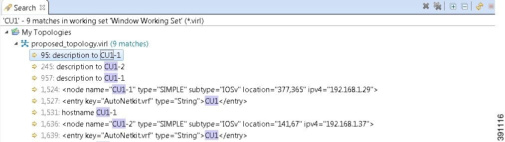
Search View
To search for text string and files, from the toolbar choose . The Search dialog box is displayed. Enter criteria for your search and click Search. The Search view displays the results of the search. A file search can be based on text strings, regular expressions, and patterns, in addition to whole words and case-sensitive characters. The scope of a file search can encompass a workspace, selected resources, or projects.
Note | Text searches are only performed on expressions contained in files with the extension .virl.
|
The Search view also displays the results of a Git search, which can be based on the same criteria as noted in a file search. However, the scope of a Git search, can encompass a particular message, resource, or identification number in the code.
Search criteria can be based on either a file or Git. The scope of a search can be general to all the topologies that are defined on Cisco Modeling Labs client or specific to a particular project or file.
- From the Cisco Modeling Labs
client toolbar, click
.
The Search dialog box appears.
- In the Containing text field, enter the text string to search for. The Containing text field displays a list of recently performed searches to select from. Leave this field empty if you want to search for files only. Check or uncheck the Case sensitive check box depending on whether a case-sensitive search is to be performed. You can also check the Regular expression check box to enable more powerful searching capabilities. Check the Whole word check box if you want to search for whole words that are identical to the text string. Specify the types of files to include in the search in the File name patterns field.
- Click Choose to open the Select Types dialog box. This dialog box provides a quick way to select from a list of valid extensions.
- In the Scope area, specify the files and folders to include in the search. Valid options are:
- Click
Search to begin
your search.
The Search view appears with the results of the search listed. You can click the Cancel tool in the Search view to cancel your search while it is still in progress.
The Search view toolbar contains the following tools:
| Icon | Function | Description |
|---|---|---|
|
|
Remove Selected Matches | Deletes all the highlighted matches from the search results. |
|
|
Remove All Matches | Deletes all the matches from the search results. |
|
|
Expand All | Expands each item in the Search view. |
|
|
Collapse All | Collapses each item in the Search view. |
|
|
Run the Current Search Again | Reruns the current search to retrieve previous search results or to reflect recent changes. |
|
|
Cancel Current Search | Cancels the search currently running. |
|
|
Show Previous Searches | Browses previously conducted searches and selects a previous search from the drop-down menu to repeat a previous search. You can also clear the search history. |
|
|
Pin the Search View | Pins the Search view so that subsequent search results are displayed in a separate Search view while the pinned view remains unchanged. This allows for a comparison of results. |
|
|
View Menu | Displays the search results as a tree or a list, filters the results using the Filters option, and sets the overall preferences for searches using the Preferences option. |
|
|
Minimize | Reduces the size of the Search view. |
|
|
Maximize | Increases the size of the Search view. |
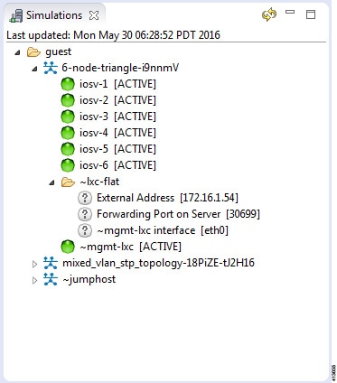
Simulations View
The Simulations view displays information about all the running simulations, including:
- Name of the user running the simulation
- Name of the topology
- Number of nodes in the running simulation
- Current state of each node
Possible simulation states are:
| State | Description |
|---|---|
| ACTIVE | Indicates that the launch worker process has successfully made all requests to OpenStack to deploy all simulation nodes. |
| STOP | Indicates that a stop simulation request has been received. |
Possible node states are:
| State | Description |
|---|---|
| ACTIVE | Indicates that the VM process is successful. It may take a few minutes for the node to boot up and configure. |
| ABSENT | Indicates that the VM is not currently deployed. |
| BUILDING | Indicates that the VM is starting but the router image has not yet loaded. |
| ERROR | Indicates that the VM process failed. |
| TERMINATING | Indicates that a request to stop the VM process has been received, without regard to the current state of the VM. |
The Simulations view toolbar contains the following tools:
| Icon | Function | Description |
|---|---|---|
|
|
Refresh the List | Refreshes the list of simulations displayed in the Simulations view. |
|
|
Minimize | Reduces the size of the Simulations view. |
|
|
Maximize | Increases the size of the Simulations view. |
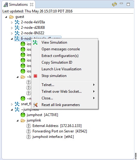
Topology Options
| Operation | Description | ||
|---|---|---|---|
| View Simulation |
Reopens the Simulation view on the canvas if it is closed. |
||
| Open Messages Console | Opens the Console view, showing the message stream from Cisco Modeling Labs server for the selected topology. Message streams contain information on the topology launch, such as the name of the launched topology, the date and time of the launch, and the current status of each node in the topology. | ||
| Extract Configurations | Extracts all the routers' configurations to a locally saved
file.
|
||
| Launch Live Visualization |
Launches the Live Visualization phase which provides a live, real-time visual representation of the running simulation in the Cisco Modeling Labs client. |
||
| Stop Simulation | Stops the running simulation. See Simulate the Topology Overview for more information on stopping and starting simulations. | ||
| Telnet |
Allows you to use Telnet to connect to ports on a node. |
||
| Telnet over WebSocket |
Allows you to use Telnet to connect over WebSockets to ports on a node. WebSockets provide full-duplex communications channels over a single connection. |
||
| Close |
Closes all port connections. |
||
| Reset All Link Parameters |
Resets all link parameters to their original setting. |
Node Options
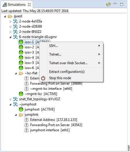
| Operation | Description | ||
|---|---|---|---|
| SSH | Allows you to use SSH to connect to ports on a node; this is available when the Management Network option Private Simulation Network is selected for the topology. | ||
| Telnet | Allows you to use Telnet to connect to ports on a node. | ||
| Telnet over Web Socket | Allows you to use Telnet to connect over WebSocket to ports on a node. WebSocket provides full-duplex communications channels over a single connection. | ||
| Extract Configurations | Allows you to extract the configurations for all routers to a
file saved locally.
|
||
| Stop this Node | Stops the selected node. | ||
| Start this Node | Starts the selected node. |
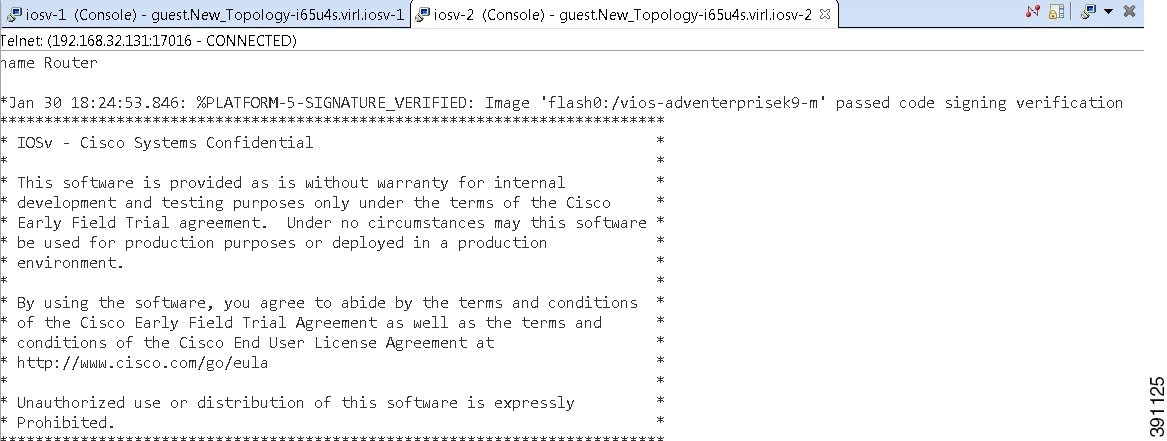
Terminal View
The Terminal view is displayed when you connect via Telnet to a node. Using the Terminal view, you can communicate with and control the operating system running on the node.
The Terminal view toolbar contains the following tools:

| Icon | Function | Description | ||
|---|---|---|---|---|
|
|
Disconnect | Disconnects the terminal connection to the node. | ||
|
|
Scroll Lock | Sets scrolling on and off. | ||
|
|
Display Selected Connections | Allows you to select a connection from the list of active terminal connections. | ||
|
|
Remove Terminal | Closes the Terminal view. | ||
|
|
Set Terminal Font | Allows you to set the font to be used in the terminal, from the
Colors
and Fonts dialog box.
|
Setting Preferences for the Cisco Modeling Labs Client
For the Cisco Modeling Labs client to operate, you must first identify certain setting preferences. These preferences are available from the menu bar under :
- Node Subtypes Setting
- Terminal Setting
- Topology Editor Setting
- Web Services Setting
- AutoNetkit Visualization Setting
- Web Browser Setting
- Secure Storage Setting
These are discussed in the following sections.
- Web Browser Setting
- Secure Storage Setting
- Node Subtypes Setting
- Packet Capture Setting
- Simulation Launch Setting
- Terminal Setting
- Topology Editor Setting
- Web Services Setting
- AutoNetkit Visualization Setting
Web Browser Setting
This setting allows you to add, remove, or edit installed browsers. The selected browser is used by default when web pages are opened in the Cisco Modeling Labs client for AutoNetkit visualization.
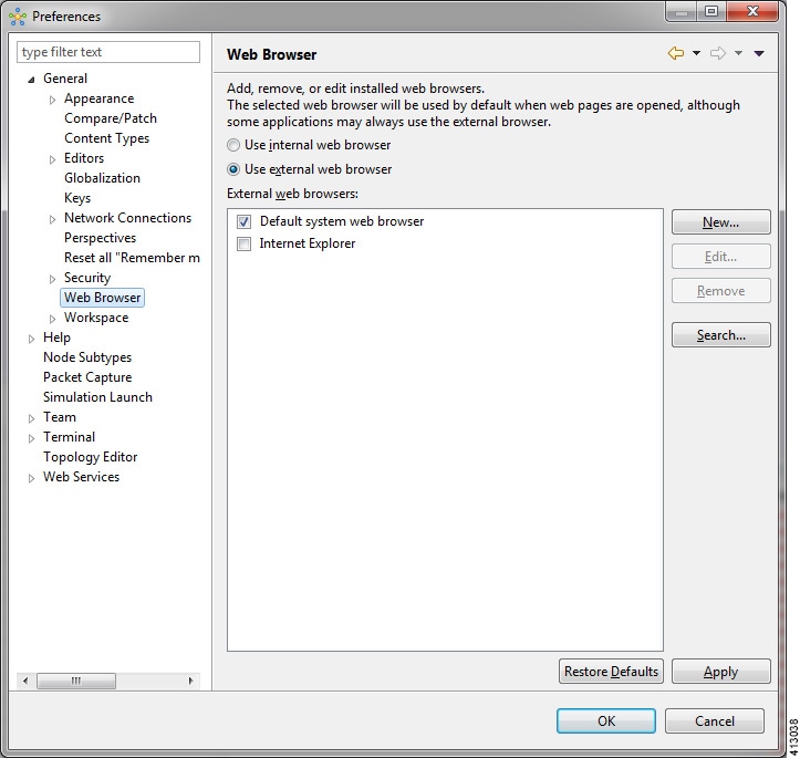
The available operations for this setting are:
| Operation | Description | ||
|---|---|---|---|
| Use Internal Web Browser | Allows you to use an internal web browser built
into the Cisco Modeling Labs client to view AutoNetkit visualization.
|
||
| Use External Web Browser | Allows you to use an external web browser. You
can add new browsers, delete or edit existing browsers, or search for new
browsers to use.
|
||
| Restore Defaults | Restores settings to the initial default state. | ||
| Apply | Applies changes. |
Secure Storage Setting
This setting configures security preferences and encryption requirements for storing system passwords.
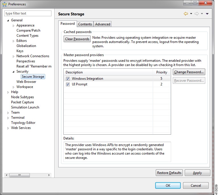
The Password tab pools functionality related to the master password life cycle and password providers.
| Option | Description | ||
|---|---|---|---|
| Clear Passwords | Clears cached master passwords from memory. | ||
| Master Password Providers | Lists the currently available password providers. By default,
the enabled provider with the highest priority is used to encrypt the data
added to secure storage. The priority range is from 0 to 10, with 10 being the
highest priority.
|
||
| Change Password | Changes the master password of the selected password provider. | ||
| Recover Password | Opens the
Password Recovery dialog box. Use this option if you
have forgotten the master password and have configured password recovery
questions. The button is disabled if the password recovery setup was cancelled
when the master password was created.
|
||
| Restore Defaults | Restores to the initial default state. | ||
| Apply | Applies changes. |
The Contents tab displays contents of the default secure storage. Secure storage is organized as a tree, where nodes represent the context of information and values associated with each node. Selecting a node in the tree displays a table of values associated with that node. Values stored in a nonencrypted form will be displayed; the encrypted values will be shown as *********. At the bottom of this tab, you will find the actual file location used to persist secure storage data. To force the changes to the contents of secure storage to be saved, click Save.
 Caution | To avoid unexpected errors, we recommend that you restart the application after secure storage has been deleted. |
The Advanced tab provides a list of algorithms to further configure secure storage. Changes in the encryption algorithm are applied only to the data stored after a change. If you have already created a secure storage, you must first delete it and then recreate it to use the newly selected encryption algorithm.
Resetting the Secure Storage Password
When the Secure Storage feature is used for the first time, it generates a master password that is used to encrypt the data. In the future, this same master password will be required to retrieve the data from secure storage. If the master password becomes unavailable, the Secure Storage feature provides optional support for password recovery.
Two methods are used to reset the password for the secure storage feature.
Method 1
- From within Cisco Modeling Labs client, choose File > Preferences > General > Security > Secure Storage.
- Click Change Password. The Secure Storage dialog box appears.
- Click Yes. The Password Recovery dialog box appears.
- Enter details in both Question fields and provide answers for both questions. Take note of the answers you provide, as these are treated as secondary passwords.
- Click OK.
Method 2
If you are unable to access the Cisco Modeling Labs client due to a lost or forgotten password for the secure storage feature, complete the following steps:
Node Subtypes Setting
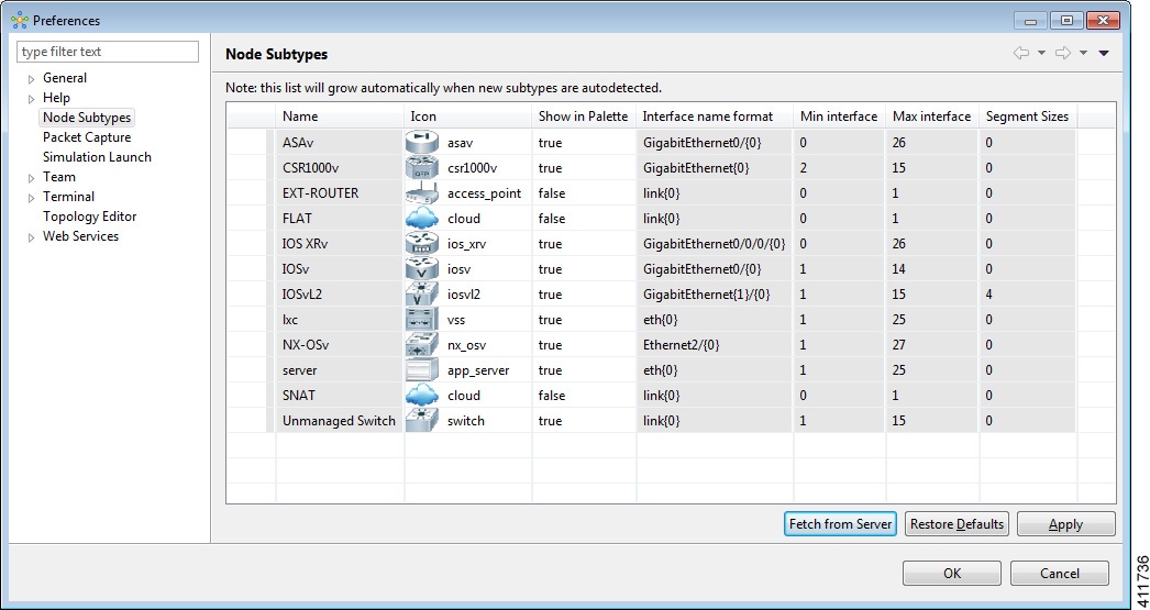
The available operations for this setting are:
| Operation | Description |
|---|---|
| Fetch from Server | Updates the local subtypes based on the currently configured Cisco Modeling Labs server. All the subtypes supported on Cisco Modeling Labs server are available with this operation. See Fetch Node Subtypes from the Cisco Modeling Labs Server. |
| Restore Defaults | Reverts to the original list of subtypes. |
| Apply | Applies changes. |
Fetch Node Subtypes from the Cisco Modeling Labs Server
To fetch new node subtypes from the Cisco Modeling Labs server, perform the following tasks:
The updated list of node subtypes is available for use in the Topology Palette view.
Contact your system administrator if a specific node subtype is missing from the list, as the system administrator is responsible for adding new node subtypes to the Cisco Modeling Labs server.
Packet Capture Setting
This setting allows you to check for suitable applications that can open .pcap files when you have downloaded packet captures. The .pcap files can be set to either open automatically or after receiving a prompt.
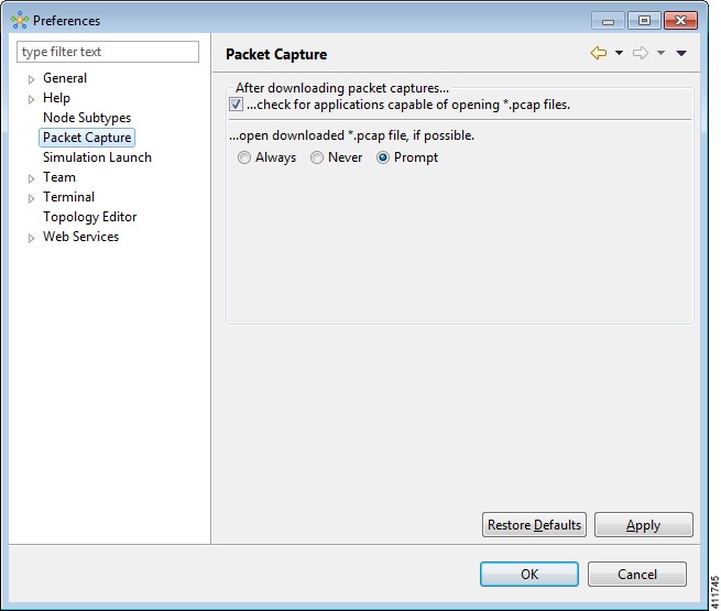
The available operations for this setting are:
| Operation | Description |
|---|---|
| Check for Applications Capable of Opening *.pcap Files | Check the checkbox box to have the system automatically check for a suitable application to open the .pcap files. |
| Open Downloaded *.pcap Files | Select the applicable option: Always, Never or Prompt for opening downloaded .pcap files. |
| Restore Defaults | Restore the settings to their initial default state. |
| Apply | Apply any changes made. |
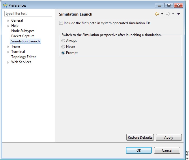
Simulation Launch Setting
This setting allows you to include the file's path in the system-generated Simulation IDs. You can set the system to either open the Simulation perspective automatically or after receiving a prompt.
The available operations for this setting are:
| Operation | Description |
|---|---|
| Include the File's Path in Sytem generated Simulation IDs. | Check this box if you want to include the file's path in the system-generated Simulation IDs. |
| Switch to the Simulation Perspective after a Simulation is Launched. | Select the applicable option: Always, Never or Prompt for switching to the Simulation perspective after a simulation is launched. |
| Restore Defaults | Restore the settings to their initial default state. |
| Apply | Apply any changes made. |
Terminal Setting
This setting allows you to launch an external terminal application, such as SecureCRT or PuTTY, or use the internal Cisco Modeling Labs client Terminal view in a separate window.
Note |
|
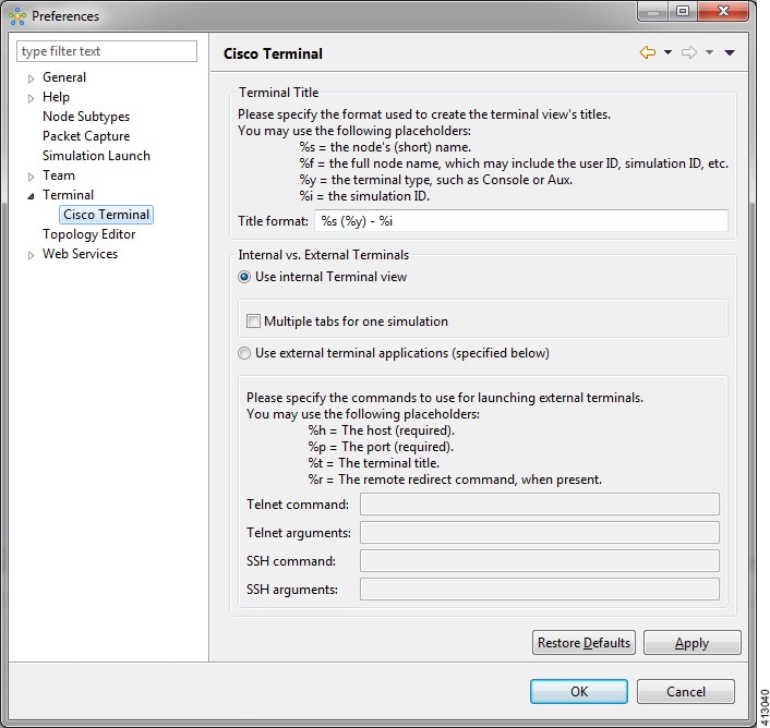
The available operations for this setting are:
| Operation | Description |
|---|---|
| Title Format | Allows you to add a Terminal view title using the required formatting characters. |
| Use Internal Terminal View | Uses the Cisco Modeling Labs internal Terminal view. |
| Multiple Tabs for One Simulation |
Opens multiple tabs in a terminal view for a running simulation. |
| Use External Terminal Application (specified below) | Uses an external terminal application, such as SSH or PuTTY. |
| Telnet Command | Specify the Telnet command to run if you are using an external terminal application. |
| Telnet Arguments | Specify the arguments for the Telnet command. |
| SSH Command | Specify the SSH command to run if you are using an external terminal application. |
| SSH Arguments | Specify the arguments for the SSH command. |
| Restore Defaults | Removes settings specified for an external terminal application and restores terminal settings to the Cisco Modeling Labs internal Terminal view. |
| Apply | Applies changes. |
Setting Up an External Terminal
This section outlines the steps involved in setting up an external terminal on Windows and OS X.
Windows
Under File > Preferences > Terminal > Cisco Terminal, update the terminal settings for connection to an external program. For example, for a PuTTY installation, configure the putty.exe binary file as the terminal program.
Note | The complete PATH must be specified. |
|
Command-Line Option |
Description |
|---|---|
|
ssh |
Opens an SSH connection |
|
telnet |
Opens a Telnet connection |
|
%h |
Specifies the host to connect to (the Cisco Modeling Labs client will not allow an external program to be set without having %h in the command line) |
|
%p |
Specifies the host to connect to (the Cisco Modeling Labs client will not allow an external program to be set without having %p in the command line) |
-
Telnet command: "C:\Program Files (x86)\PuTTY\putty.exe" -telnet %h %p
-
SSH command: "C:\Program Files (x86)\PuTTY\putty.exe" -ssh %h %p
Note | The double quotes (" ") must enclose the PATH to allow the use of spaces within the PATH. Select the Use external terminal application (specified below) radio button to use an external terminal. |
|
Terminal Program |
Connection Type |
Command to Use |
||
|---|---|---|---|---|
|
Xshell |
Telnet |
"C:\Program Files (x86)\NetSarang\Xshell 4\xshell.exe" -url telnet://%h:%p -newtab %t |
||
|
SecureCRT |
Telnet |
|
OS X
-
AppleScript: A program used to start applications and interact with them; some examples are open windows, start new sessions, paste keyboard input into a session, and so on.
-
/usr/bin/osascript: A built-in OS X command-line utility used to execute AppleScript and other OSA language scripts. This is configured in the Cisco Modeling Labs client; it is essentially the glue between the Cisco Modeling Labs client and the terminal application.
|
Terminal Program |
Connection Type |
Command to Use |
|---|---|---|
|
iTerm |
Telnet |
/usr/bin/osascript /Users/your-user-id/iterm.scpt telnet %h %p %t |
|
|
SSH |
/usr/bin/osascript /Users/your-user-id/iterm.scpt telnet %h %p %t |
|
Terminal.app |
Telnet |
/usr/bin/osascript /Users/your-user-id/iterm.scpt ssh %h %p %t |
|
|
SSH |
/usr/bin/osascript /Users/your-user-id/terminal.scpt ssh %h %p %t |
The following are AppleScript scripts that are used to set up an external terminal.
on run argv
    tell application "iTerm"
        activate
        if current terminal exists then
            set t to current terminal
        else
            set t to (make new terminal)
        end if

        tell t
            launch session "Default Session"
            tell the current session
                write text "/usr/bin/" & item 1 of argv & " " & item 2 of argv & " " & item 3 of argv
                set name to item 4 of argv
            end tell
        end tell
    end tell
end run
on run argv
    tell application "Terminal"
        activate
        -- open a new Tab - there is no method
        tell application "System Events"
            keystroke "t" using {command down}
        end tell
        repeat with win in windows
            try
                if get frontmost of win is true then
                    set cmd to "/usr/bin/" & item 1 of argv & " " & item 2 of argv & " " & item 3 of argv
                    do script cmd in (selected tab of win)
                    set custom title of (selected tab of win) to item 4 of argv
                end if
            end try
        end repeat
    end tell
end run
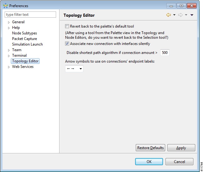
Topology Editor Setting
This setting allows you to customize the Topology Editor in the Cisco Modeling Labs client.
The available operations for this setting are:
| Operation | Description |
|---|---|
| Revert Back to the Palette's Default Tool | Resets the definition of the Palette view tools Select and Connect to their default configuration. This option is disabled by default. |
| Associate New Connection with Interfaces Silently | Enables the following: |
| Disable Shortest Path Algorithm if Connection Amount > (Greater than) | Enables the following: |
| Restore Defaults | Restores settings to the initial default state. |
| Apply | Applies changes. |
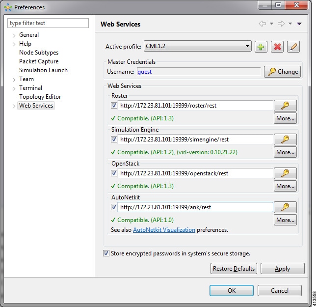
Web Services Setting
This setting allows you to configure the Cisco Modeling Labs client to communicate with the Cisco Modeling Labs server. When you first launch the Cisco Modeling Labs client, the Active profile is not specified and the web services that are listed display Unauthorized in red. This message relates to the Master Credentials field, which must be set before the Cisco Modeling Labs client can communicate with the Cisco Modeling Labs server.
The available operations for this setting are:
| Operation | Description | ||
|---|---|---|---|
| Active Profile | Identifies an active profile that has been defined on the Cisco Modeling Labs client. You can define a new active profile and edit or delete an existing active profile. | ||
| Master Credentials | Specifies a username and password for accessing the Cisco Modeling Labs server. These credentials are provided by the system administrator. | ||
| Web Services |
|
||
| Store Encrypted Passwords in System's Secure Storage | Encrypts passwords and stores them locally on the Cisco Modeling Labs client. To change the settings for managing the encrypted passwords, choose . See Secure Storage Setting for more information. | ||
| Restore Defaults | Restores settings to the initial default state. | ||
| Apply | Applies changes. |
AutoNetkit Visualization Setting
The AutoNetkit visualization feature is available only when node configurations are built using the parameters defined in AutoNetkit. If AutoNetkit visualization is turned off, you cannot get a true representation of your topology.
AutoNetkit visualization is used to determine how AutoNetkit presents graphical representations of topology-specific attributes, such as nodes, links, and interfaces, during the build phase. The graphical representations can be presented as a physical perspective of a network topology or based on a protocol perspective.
For AutoNetkit visualization to operate, the Cisco Modeling Labs client must be connected to the Cisco Modeling Labs server. The nodes in the network topology must be set to open AutoNetkit visualization either automatically or after receiving a prompt.
To access this setting, choose .
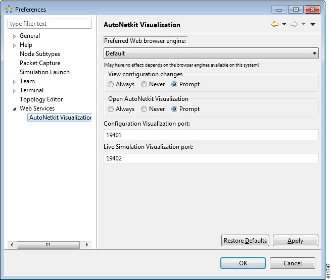
The available operations for this setting are:
| Operation | Description | ||
|---|---|---|---|
| Preferred Web Browser Engine | Specifies the external web browser to use when
displaying AutoNetkit visualization results. Options are:
|
||
| View Configuration Changes | Specifies whether to view configuration changes after a new build is generated. Options are: The default value is Prompt. | ||
| Open AutoNetkit Visualization | Specifies when to open a browser window to display AutoNetkit visualization. Options are: The default value is Prompt. | ||
| Configuration Visualization Port | Assigns a port value to the web service
supporting AutoNetkit visualization. The default port is
19401. However, the port might need to be changed depending
on your network, for example, if a firewall is blocking that port. The port
value should be provided by the system administrator.
|
||
| Live Simulation Visualization Port | Assigns a port value to the web service
supporting Live Visualization. The default port is
19402. However, the port might need to be changed depending
on your network, for example, if a firewall is blocking that port. The port
value should be provided by the system administrator.
|
||
| Restore Defaults | Restores the default state for the preferred web browser engine and restores the default port values assigned to AutoNetkit visualization and Live Visualization. | ||
| Apply | Applies any changes made. |
 Feedback