Installing the Cisco Modeling Labs Client
Installing the Cisco Modeling Labs Client
The Cisco Modeling Labs client is a powerful cross-platform user interface for creating and editing topologies, and simulating those topologies on the Cisco Modeling Labs server. You can quickly create and edit complex topologies using a graphical point-and-click editor. You can also interact directly with your running simulations from the user interface.
Cisco Modeling Labs Client Requirements
| Requirement | Description |
|---|---|
| Operating System | Either of the following: |
| Memory (RAM) | 500 MB |
| Disk Space | 150 MB |
Downloading Cisco Modeling Labs Client
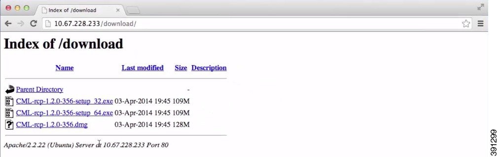
| Step 1 | Open a web
browser and enter the IP address or hostname for the Cisco Modeling Labs server
and include "/download," as shown in the following figure.
|
| Step 2 | Click the file that is appropriate for your operating system and hardware to start the download. |
What to Do Next
See sections Windows Installation Process and Mac OS X Installation Process for more information.
Windows Installation Process
| Step 1 | After the selected .exe file has finished downloading, double-click it to start the Cisco Modeling Labs client installation. |
| Step 2 | In the Cisco Modeling Labs Setup wizard, click Next. |
| Step 3 | Review the License Agreement and click Agree. |
| Step 4 | In the Choose Install Location window, click Browse to navigate to a new location, or click Next to choose the default location. |
| Step 5 | In the Choose Start Menu Folder window, choose the default and click Next. |
| Step 6 | In the Installation Type window, accept the defaults and click Install. The installation process begins. |
| Step 7 | When the installation completes, click Finish. The Cisco Modeling Labs client opens. |
What to Do Next
The next step is to configure the Cisco Modeling Labs client to communicate with the Cisco Modeling Labs server, as described in the section Creating a Web Services Profile.
Mac OS X Installation Process
| Step 1 | After the selected .dmg package is downloaded, open it. |
| Step 2 | (Optional) Rename the <rcp-xxx> folder as Cisco Modeling Labs. |
| Step 3 | Click the Cisco Modeling Labs folder, and drag-and-drop it into the Applications folder. |
| Step 4 | (Optional) Drag the CML.app button from the folder to your desktop. |
| Step 5 | Double-click the CML.app button to open the Cisco Modeling Labs client. |
| Step 6 | Review the License Agreement and then click Agree. The Cisco Modeling Labs client opens. |
What to Do Next
The next step is to configure the Cisco Modeling Labs client to communicate with the Cisco Modeling Labs server, as described in the section Creating a Web Services Profile.
Creating a Web Services Profile
- Ensure that you know the appropriate IP address or hostname of the Cisco Modeling Labs server.
- Ensure that you know the Web Services port number.
- Ensure that you know the username and password for connecting to the Cisco Modeling Labs server. The username and password should be provided by your system administrator.
| Step 1 | On Windows,
choose
.
On OS X, choose . | ||
| Step 2 | Click the
Add New
Profile button to open the
Web
Services Profile dialog box, which is shown in the following figure.
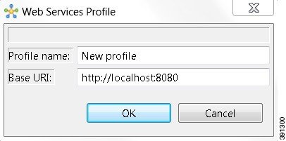 | ||
| Step 3 | In the Profile name field, enter a name for your profile. | ||
| Step 4 | Update the
Base URI
field with the IP address of the Cisco Modeling Labs server you are connecting
to. Use the format
http://<IP address |
hostname>:8080, (for example,
http://10.10.10.10:8080).
| ||
| Step 5 | Click OK. | ||
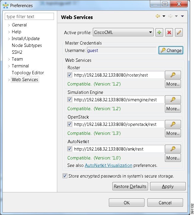
| Step 6 | Log in to the
Cisco Modeling Labs client using the credentials provided by your system
administrator. Ensure that the word Compatible (shown in green) is displayed
for each field, indicating that Web Services are correctly configured, as shown
in the following figure.
| ||
| Step 7 | Click Apply and then click OK to save the changes. |
What to Do Next
Verify the communications channel exists between the Cisco Modeling Labs client and the Cisco Modeling Labs server by creating and launching a simulation.
Verifying Your Cisco Modeling Labs Installation
| Step 1 |
On
Windows: From the Cisco Modeling Labs 1.0 client menu bar, choose
.
On OS X: From the Cisco Modeling Labs 1.0 client menu bar, choose File > New > Project. | ||
| Step 2 | On Windows: Enter
Topology
for the project name, and click
Finish.
On OS X: Choose Topology > Topology Project, and select Next. Enter the topology project name, and click Finish. | ||
| Step 3 | On Windows:
Choose
Projects >
Topology, then choose
to create a sample topology
to verify your Cisco Modeling Labs 1.0 client installation.
On OS X: Choose File > New > Other to create a sample topology to verify your Cisco Modeling Labs 1.0 client installation. | ||
| Step 4 | On Windows: Enter topology.virl for the topology name, and click Finish. On OS X: Choose Topology > Topology and click Next. Select the Parent folder and enter the filename topology.virl. Click Finish. | ||
| Step 5 | Choose and click IOSv to add a Cisco IOSv device to the topology. | ||
| Step 6 | Click anywhere on the canvas to position the device, and click the canvas two more times to add two more devices. | ||
| Step 7 | Choose
and click
Connect to
create links between the three devices:
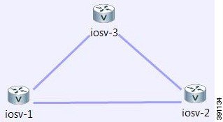 | ||
| Step 8 | From the toolbar, click the Save button to save the topology. | ||
| Step 9 | From the toolbar, click the Launch Simulation button to run the simulation. In the Simulations view, you will see that the node states are [ACTIVE], meaning the nodes are running and ready for use. | ||
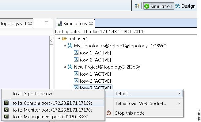
| Step 10 | Right-click the
corresponding node and choose
, as shown in the following figure.
| ||
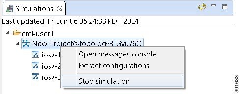
| Step 11 | (Optional) To
stop the simulation, in the
Simulations view, right-click the simulation name and
select
Stop
simulation, as shown in the following figure.
 | ||
| Step 12 | (Optional) To
delete a sample topology, select the topology in the
Projects view, and click the
Delete icon
in the toolbar.
See the Cisco Modeling Labs 1.0 online help and Cisco Modeling Labs 1.0 User Guide for more information. |
 Feedback