Configure the 44/56 Core Appliance Using the Browser-Based Wizard

Appliance Configuration Overview

You can deploy the 44 or 56-core appliance in your network in one of the following modes:

  • Standalone: As a single node offering all the functions. This option is usually preferred for initial or test deployments and in smaller network environments. If you choose Standalone mode for your initial deployment, this will be your first, or primary, node. Note that you can add more appliances later to form a cluster.

  • Cluster: As a node that belongs to a three-node cluster. In this mode, all the services and data are shared among the hosts. This is the preferred option for large deployments. If you choose Cluster mode for your initial deployment, be sure to finish configuring the primary node before configuring the secondary nodes.

To proceed, complete the following tasks:

  1. Configure the primary node in your cluster (see Configure the Primary Node Using the Expert Configuration Wizard).

  2. If you have installed three appliances and want to add the second and third nodes to your cluster, see Configure a Secondary Node Using the Expert Configuration Wizard.

Browser-Based Wizard Prerequisites

To use the browser-based wizard and ensure that it configures your appliance properly, do the following:

  • Designate the Enterprise interface on your appliance to use the IP address, subnet mask, and default gateway that a DHCP server assigns to it. When you configure this interface in the wizard, you will not be able to change the IP address or subnet mask that have been assigned to it. You will only be able to change its default gateway. The topics in this chapter assume that the Enterprise interface was chosen for this purpose.

  • Confirm that the IP address assigned by the DHCP server is reachable by the machine from which you will complete the wizard.

  • For the Enterprise and Intracluster interfaces, verify that both interfaces are connected and in the UP state.

Configure the Primary Node Using the Expert Configuration Wizard

Perform the following steps to configure the first installed appliance as the primary node using the Expert Configuration wizard. You must always configure the first appliance as the primary node, whether it will operate standalone or as part of a cluster.


Important

The following second generation Cisco DNA Center appliances support configuration using this wizard:

  • 44-core appliance: Cisco part number DN2-HW-APL

  • 44-core promotional appliance: Cisco part number DN2-HW-APL-U

  • 56-core appliance: Cisco part number DN2-HW-APL-L

  • 56-core promotional appliance: Cisco part number DN2-HW-APL-L-U

The first generation 44-core Cisco DNA Center appliance (Cisco part number DN1-HW-APL) cannot be configured using this wizard.


If you are configuring the installed appliance as a secondary node for an existing cluster that already has a primary node, follow the steps in Configure a Secondary Node Using the Expert Configuration Wizard instead.


Note

Ensure that all of the IP addresses you enter while completing this procedure are valid IPv4 addresses with valid IPv4 netmasks. Also make sure that the addresses and their corresponding subnets do not overlap. Service communication issues can result if they do.


Before you begin

Ensure that you:

  • Installed the Cisco DNA Center software image onto your appliance, as described in Reimage the Appliance.


    Important

    This is only applicable if you are going to configure a promotional appliance, because the Cisco DNA Center software image is not preinstalled on the following appliances:

    • 44-core promotional appliance (Cisco part number DN2-HW-APL-U)

    • 56-core promotional appliance: (Cisco part number DN2-HW-APL-L-U)


  • Collected all of the information called for in Required IP Addresses and Subnets and Required Configuration Information.

  • Installed the first appliance as described in Appliance Installation Workflow.

  • Configured Cisco IMC browser access on the primary node, as described in Enable Browser Access to Cisco Integrated Management Controller.

  • Checked that the primary node's ports and the switches it uses are properly configured, as described in Execute Preconfiguration Checks.

  • Are using a browser that is compatible with Cisco IMC and Cisco DNA Center. For a list of compatible browsers, see the Release Notes for the version of Cisco DNA Center you are installing.

  • Enabled ICMP on the firewall between Cisco DNA Center and both the default gateway and the DNS server you specify in the following procedure. The wizard uses ping to verify the gateway and DNS server you specify. This ping might get blocked if a firewall is in place and ICMP is not enabled on that firewall. When this happens, you will not be able to complete the wizard.

Procedure


Step 1

Start the Expert Configuration wizard:

  1. Point your browser to the Cisco IMC IP address you set during the Cisco IMC GUI configuration you performed, then log in to the Cisco IMC GUI as the Cisco IMC user (see Enable Browser Access to Cisco Integrated Management Controller).

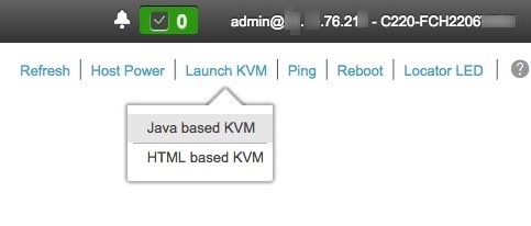
    After successful login, the appliance displays the Cisco Integrated Management Controller Chassis Summary window, with a blue link menu at the upper right, as shown below.
  2. From the blue link menu, choose Launch KVM and then select either Java based KVM or HTML based KVM. If you select the Java-based KVM, you will need to launch the Java startup file from your browser or file manager in order to view the KVM console in its own window. If you select the HMTL-based KVM, it will launch the KVM console in a separate browser window or tab automatically.

    Irrespective of the KVM type you choose, use the KVM console to monitor the progress of the configuration and respond to Maglev Configuration Wizard prompts.

  3. With the KVM displayed, reboot the appliance by making one of the following selections:

    • In the main Cisco IMC GUI browser window: Choose Host Power > Power Cycle. Then switch to the KVM console to continue.

    • In the KVM console: Choose Power > Power Cycle System (cold boot).

    If asked to confirm your choice to reboot the appliance, click OK.

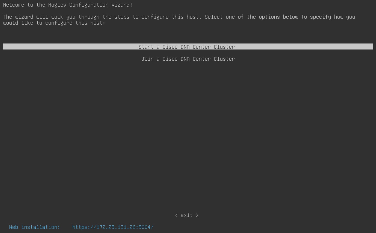
    After displaying reboot messages, the KVM console displays the Maglev Configuration wizard welcome screen.

    Note the URL listed in the Web Installation field.

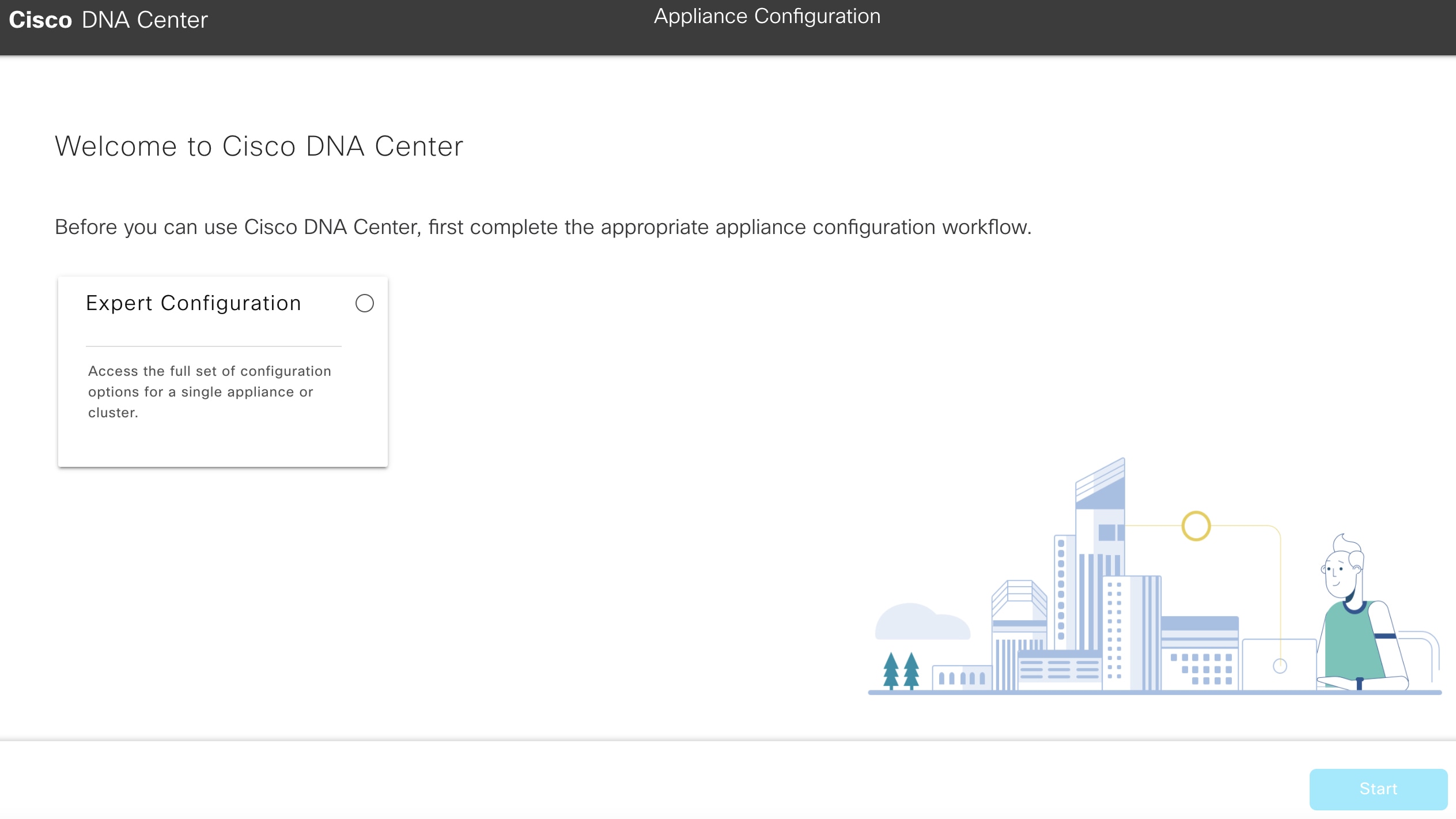
  4. Open this URL to bring up the Appliance Configuration screen.

  5. Click the Expert Configuration radio button, then click Start.

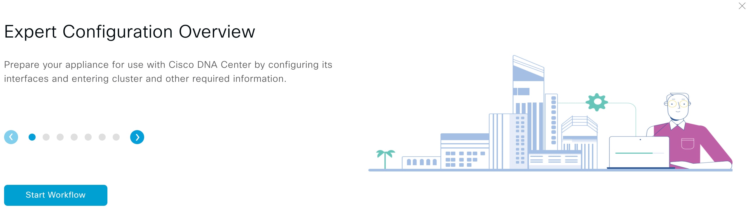
    The Expert Configuration Overview slider opens. Click > to view a summary of the tasks that the wizard will help you complete.

  6. Click Start Workflow to start the wizard.

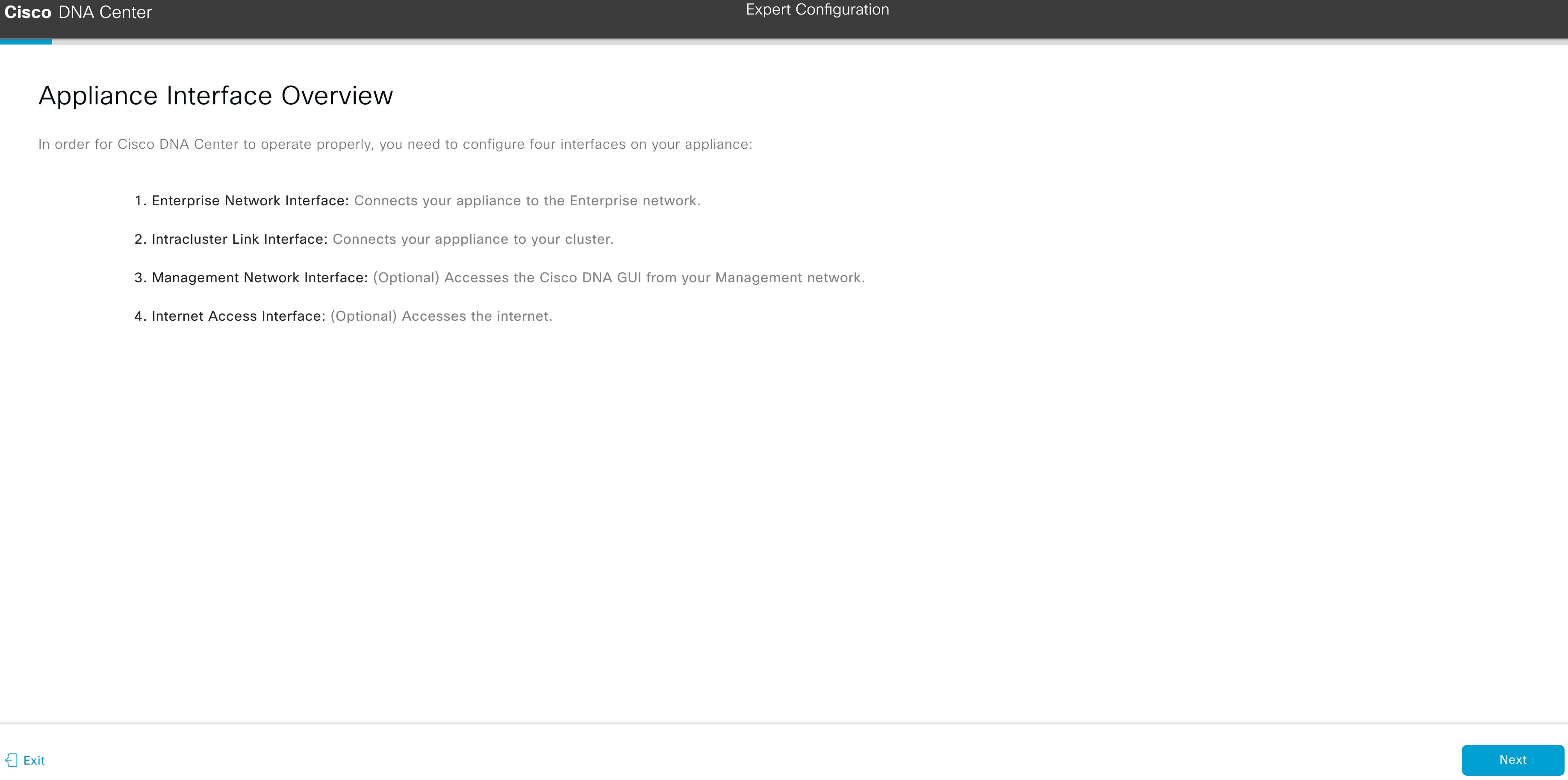
    The Appliance Interface Overview screen opens, providing a description of the four appliance interfaces that you can configure.

    At a minimum, you must configure the interfaces on your appliance's Enterprise and Cluster ports, as they are required for Cisco DNA Center functionality. If the wizard fails to display either or both of these ports during the course of configuration, they may be non-functional or disabled. If you discover that they are non-functional, choose Exit to exit the wizard immediately. Be sure you have completed all of the steps provided in Execute Preconfiguration Checks before resuming configuration or contacting the Cisco Technical Assistance Center (TAC).

Step 2

Complete the Expert Configuration wizard:

  1. Click Next.

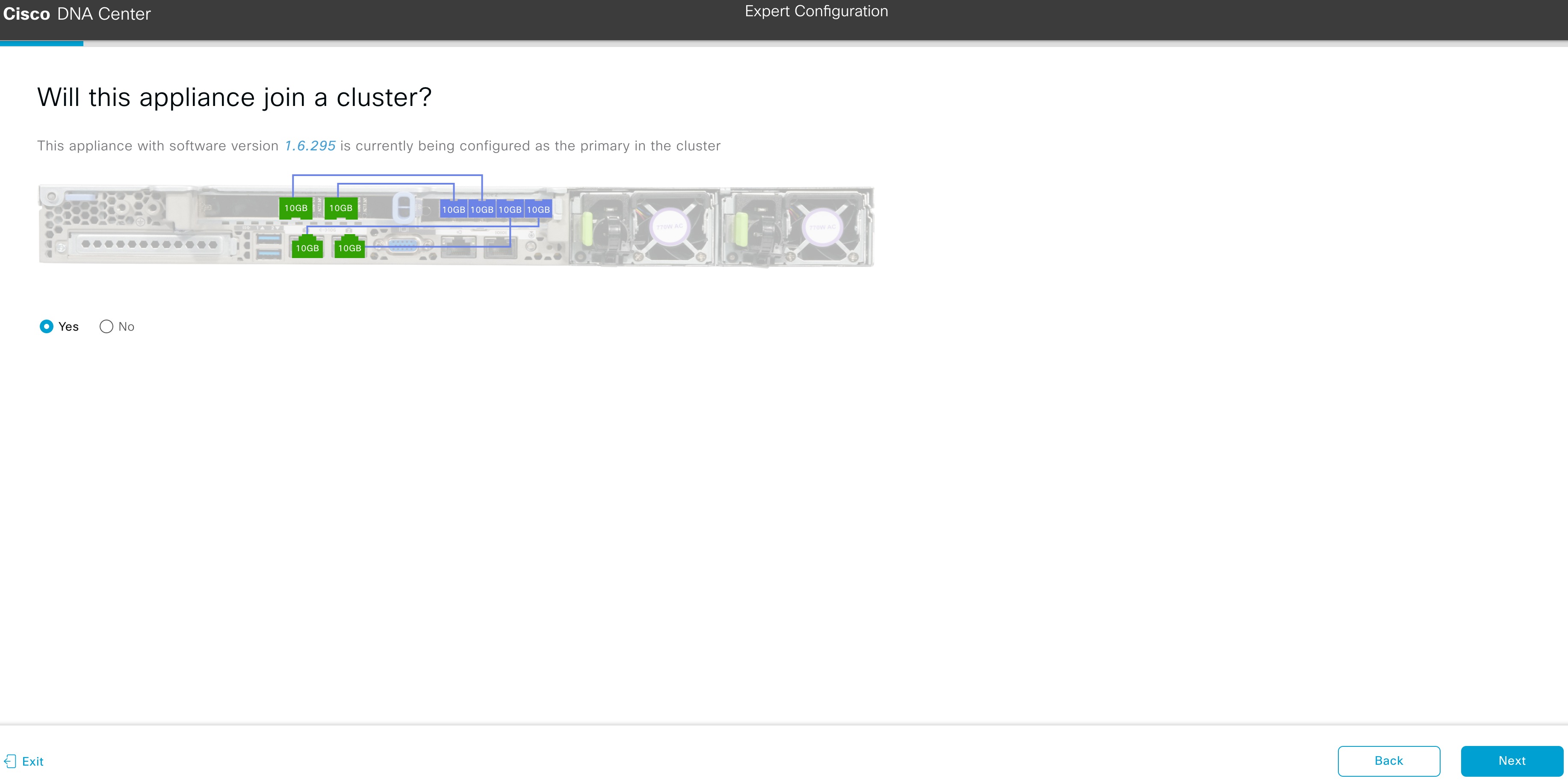
    The Will this appliance join a cluster? screen opens.
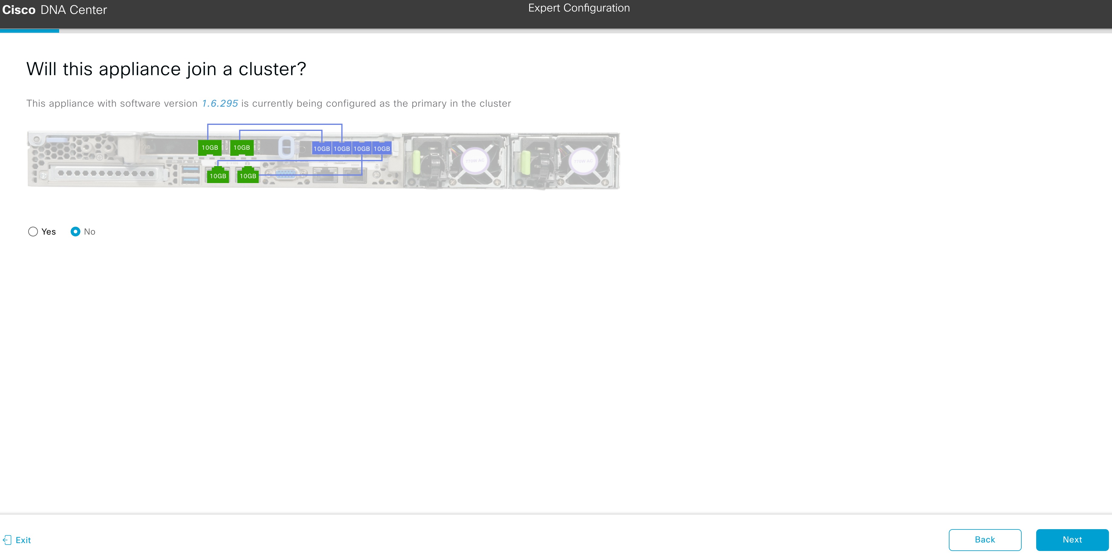
  2. Click the No radio button (as you are configuring your cluster's primary node), then click Next.

    The How would you like to set up your appliance interfaces? screen opens.
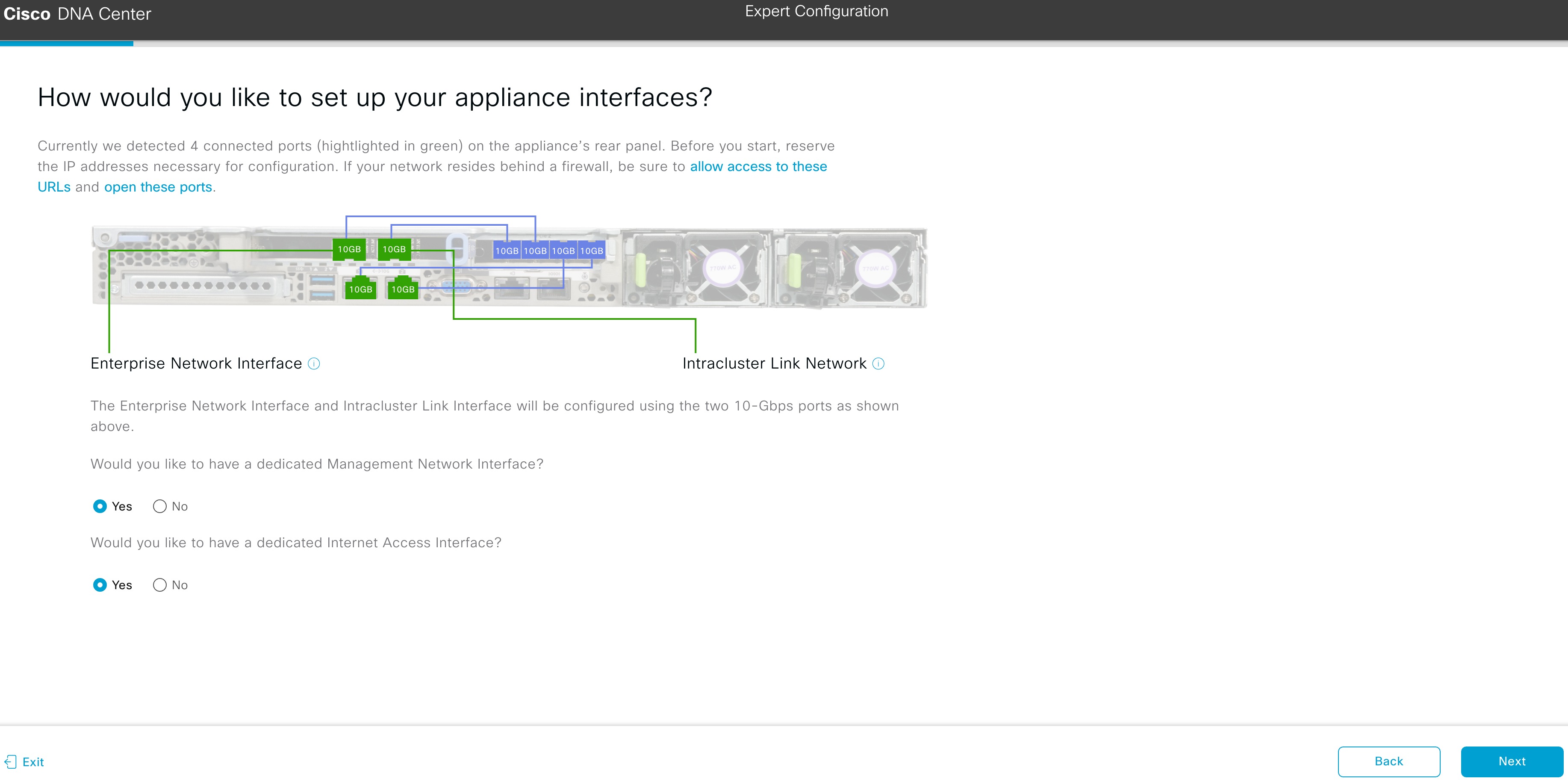
    If your network resides behind a firewall, do the following:

    • Click the allow access to these URLs link to view a popup window that lists the URLs that Cisco DNA Center must be able to access.

    • Click the open these ports link to view a popup window that lists the network service ports that must be available for Cisco DNA Center to use.

  3. Indicate whether you want to configure dedicated Management and Internet Access interfaces, then click Next.

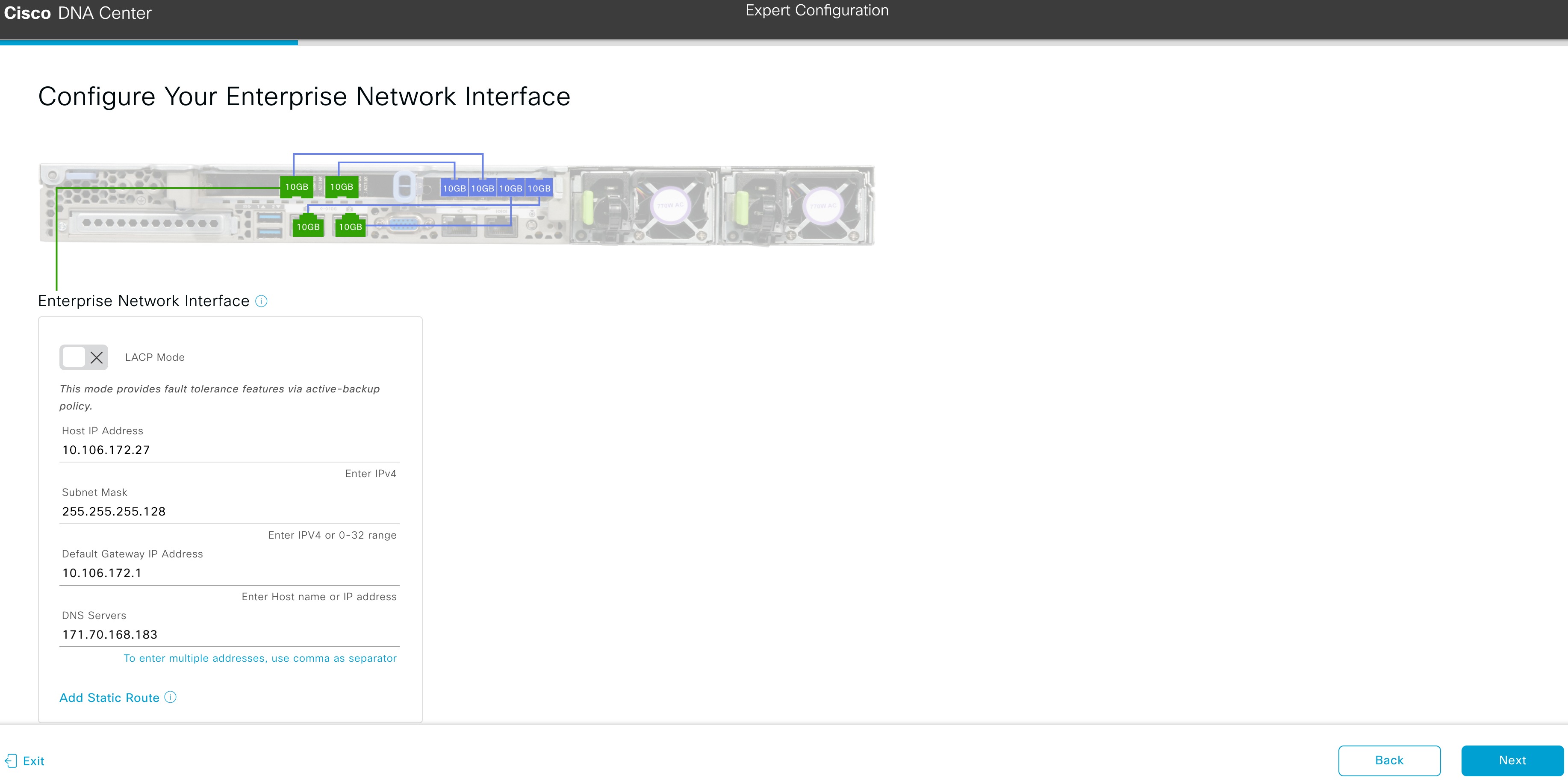
    The Configure Your Enterprise Network Interface screen opens.
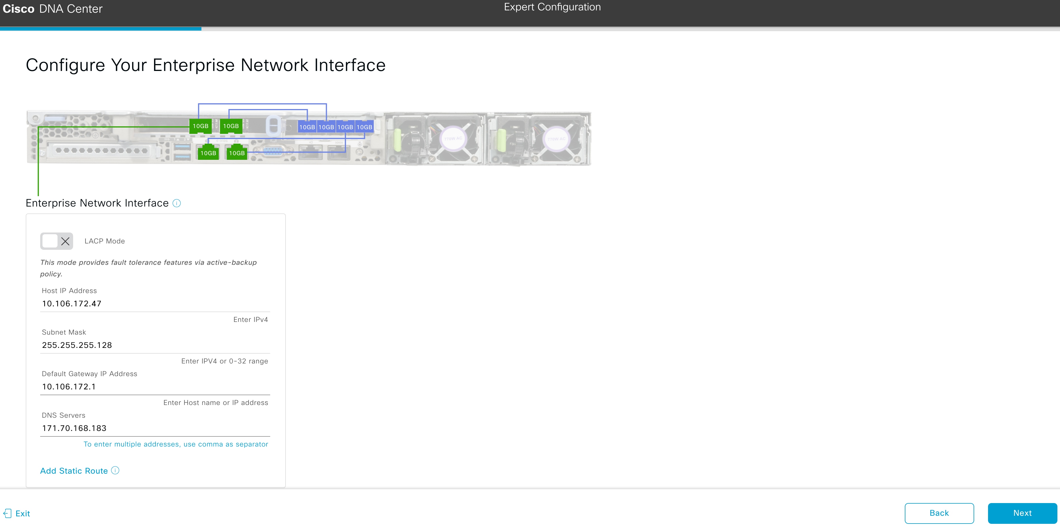
  4. Enter configuration values for the Enterprise interface.

    As explained in Interface Cable Connections, this is a required interface used to link the appliance to the enterprise network. See Required IP Addresses and Subnets and Required Configuration Information for a more detailed description of the values you need to enter.

    Note 
    • If you opted to configure the Enterprise and Internet Access interfaces on the same port, complete this step and then proceed to Step 2e (which describes how to configure your Management interface).

    • If you opted to configure the Enterprise and Management interfaces on the same port, complete this step and then skip ahead to Step 2f (which describes how to configure your Internet Access interface).

    • If you opted to configure the Enterprise, Management, and Internet Access interfaces on the same port, complete this step and then skip ahead to Step 2g (which describes how to configure your Intracluster interface).

    Table 1. Primary Node Entries for the Enterprise Interface

    LACP Mode slider

    Choose one of the following network interface controller (NIC) bonding modes for the Enterprise interface:

    • Active-Backup mode: This mode provides fault tolerance by aggregating two Ethernet interfaces into a single logical channel. When the interface that's currently active goes down, the other interface takes its place and becomes active.

    • LACP mode: This mode aggregates two Ethernet interfaces that share the same speed and duplex settings into a single logical channel. This provides load balancing and higher bandwidth.

    For more information about Cisco DNA Center's implementation of NIC bonding, see NIC Bonding Overview.

    Host IP Address field

    Enter the IP address for the Enterprise port. This is required.

    Subnet Mask field

    Enter the netmask for the port's IP address. This is required.

    Default Gateway IP Address field

    Enter a default gateway IP address to use for the port.

    Important 

    Ensure that you enter a default gateway IP address for at least one of your appliance's interfaces. Otherwise, you will not be able to complete the configuration wizard.

    Note 

    You designated this interface to use the default gateway assigned to it by a DHCP server. Complete the following steps to specify a different gateway:

    1. Delete the IP address that is currently listed in this field and then click Exit.

      This will bring you back to the first wizard screen.

    2. Return to the Enterprise port's wizard screen and enter the gateway IP address you want to use.

    DNS Servers field

    Enter the IP address of the preferred DNS server. If entering multiple DNS servers, separate the IP addresses in the list with commas.

    Important 

    For each node in your cluster, configure a maximum of three DNS servers. Problems can occur if you configure more than three DNS servers for an appliance.

    Add Static Route link

    To configure a static route, click this link and then do the following:

    1. Enter the route's network IP prefix, subnet mask, and nexthop IP address.

      To configure additional static routes, click +.

    2. Click Add.

    From here, do one of the following:

    • To close the wizard, click Exit. A popup window appears, indicating that the settings you have entered up to this point will be saved. Click Exit again to confirm that you want to close the wizard. When you restart the wizard and return to this screen, the settings that you entered previously will already be populated.

    • To return to the previous wizard screen, click Back.

    • To proceed to the next wizard screen, click Next.

      The wizard validates the information you have entered, confirms that the port is up, and notifies you of any settings that need to be changed before you can proceed with the wizard. If the settings you have entered are valid and the port is up, the wizard's Configure Your Management Network Interface screen opens.
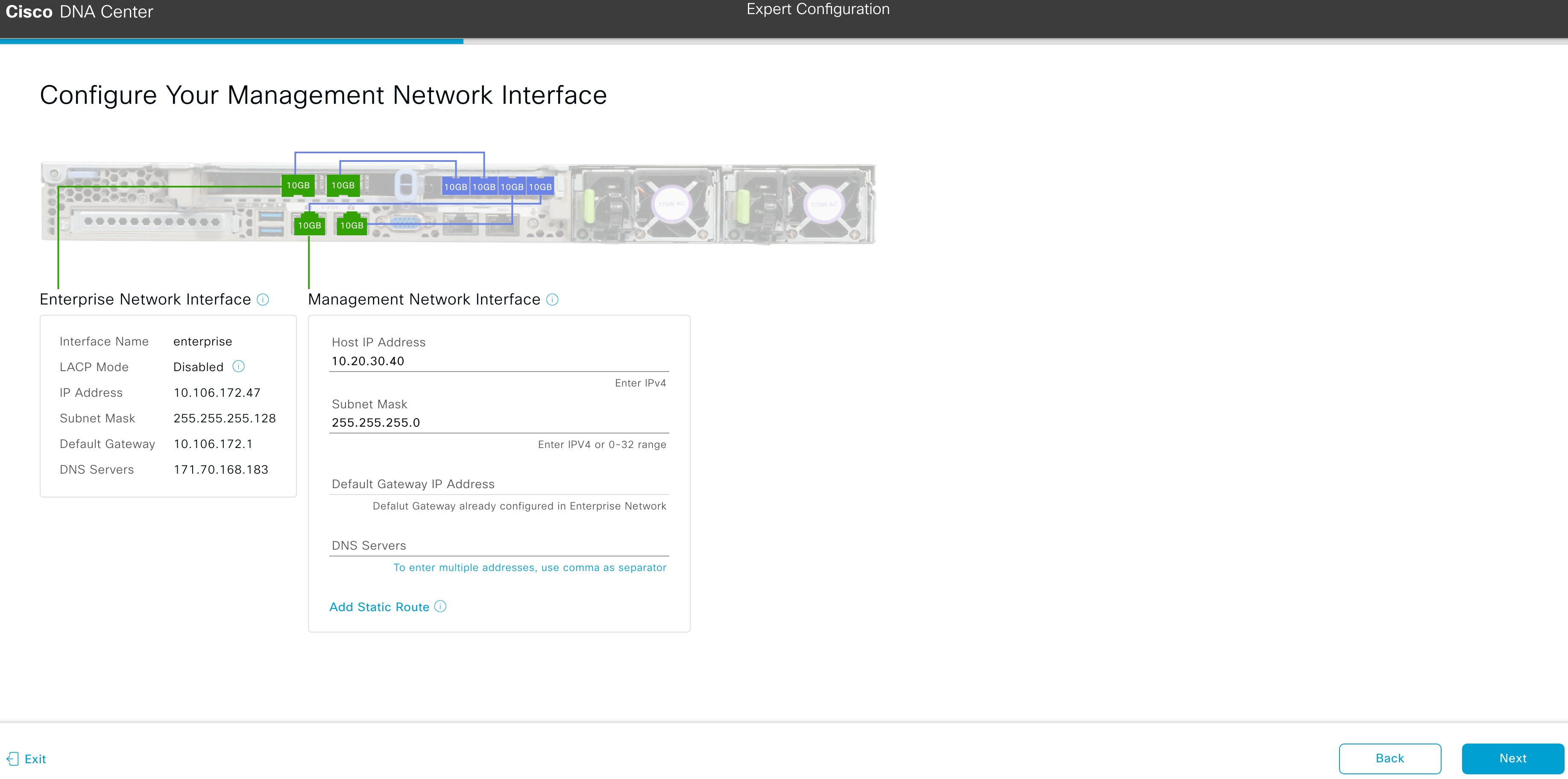
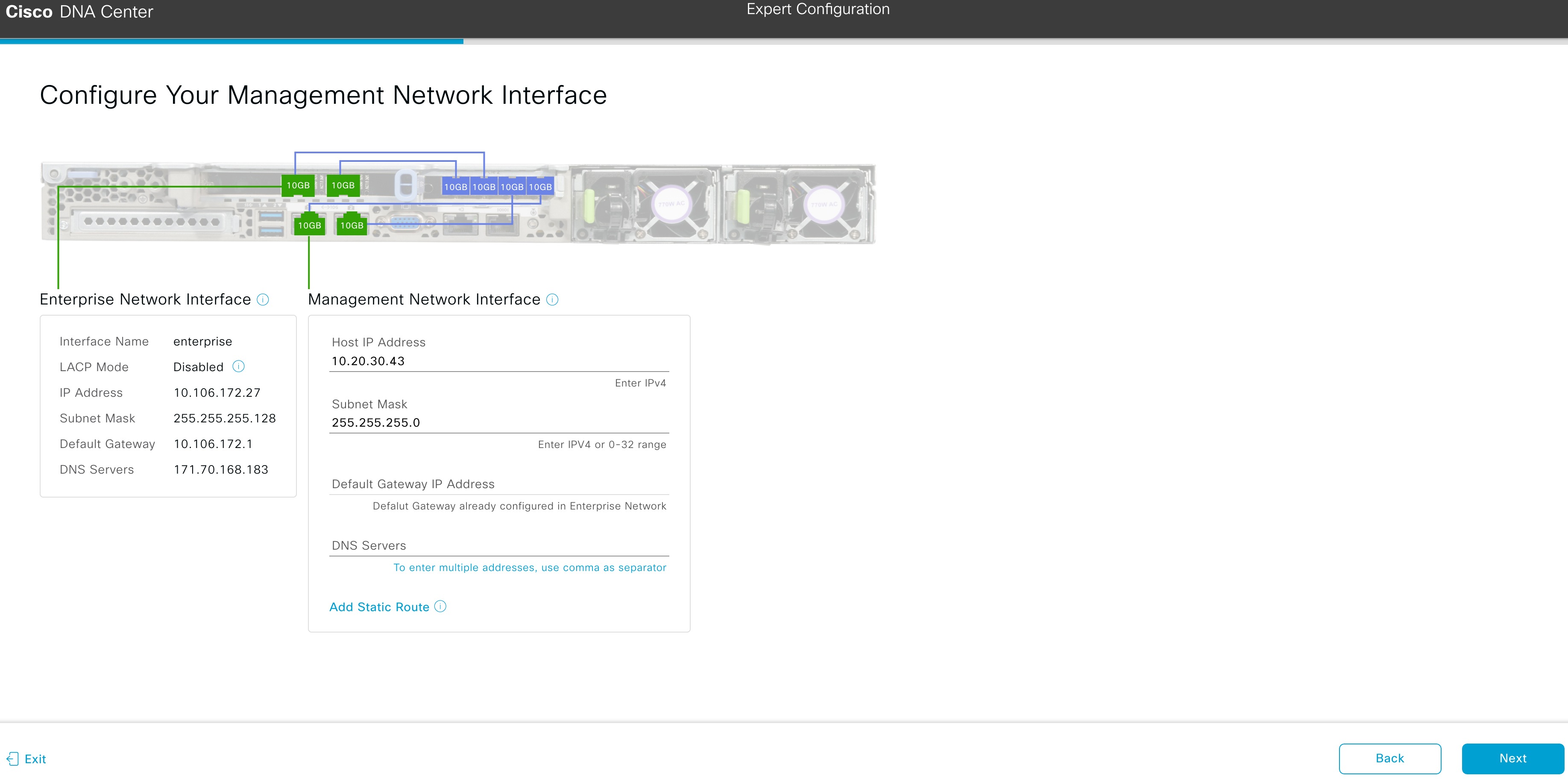
  5. (Optional) Enter configuration values for the Management port.

    As explained in Interface Cable Connections, this port is used to access the Cisco DNA Center GUI from your management network. If you chose to configure a dedicated Management interface, enter the information described in the following table. (See Required IP Addresses and Subnets and Required Configuration Information for a more detailed description of the values you need to enter.)

    Note 
    • If you opted to configure the Enterprise and Management interfaces on the same port, skip this step and proceed to Step 2f (which describes how to configure your Internet Access interface).

    • If you opted to configure the Enterprise, Management, and Internet Access interfaces on the same port, skip this step and proceed to Step 2g (which describes how to configure your Intracluster interface).

    Table 2. Primary Node Entries for the Management Port

    Host IP Address field

    Enter the IP address for the Management port. This is required.

    Subnet Mask field

    Enter the netmask for the port's IP address. This is required.

    Default Gateway IP Address field

    Enter a default gateway IP address to use for the port.

    Important 

    Ensure that you enter a default gateway IP address for at least one of your appliance's interfaces. Otherwise, you will not be able to complete the configuration wizard.

    DNS Servers field

    Enter the IP address of the preferred DNS server. If entering multiple DNS servers, separate the IP addresses in the list with spaces.

    Important 
    • For NTP, ensure port 123 (UDP) is open between Cisco DNA Center and your NTP server.

    • For each appliance in your cluster, configure a maximum of three DNS servers. Problems can occur if you configure more than three DNS servers for a node.

    Add Static Route link

    To configure a static route, click this link and then do the following:

    1. Enter the route's network IP prefix, subnet mask, and nexthop IP address.

      To configure additional static routes, click +.

    2. Click Add.

    From here, do one of the following:

    • To close the wizard, click Exit. A popup window appears, indicating that the settings you have entered up to this point will be saved. Click Exit again to confirm that you want to close the wizard. When you restart the wizard and return to this screen, the settings that you entered previously will already be populated.

    • To return to the previous wizard screen, click Back.

    • To proceed to the next wizard screen, click Next.

      The wizard validates the information you have entered, confirms that the port is up, and notifies you of any settings that need to be changed before you can proceed with the wizard. If the settings you have entered are valid and the port is up, the wizard's Configure Your Internet Access Interface screen opens.
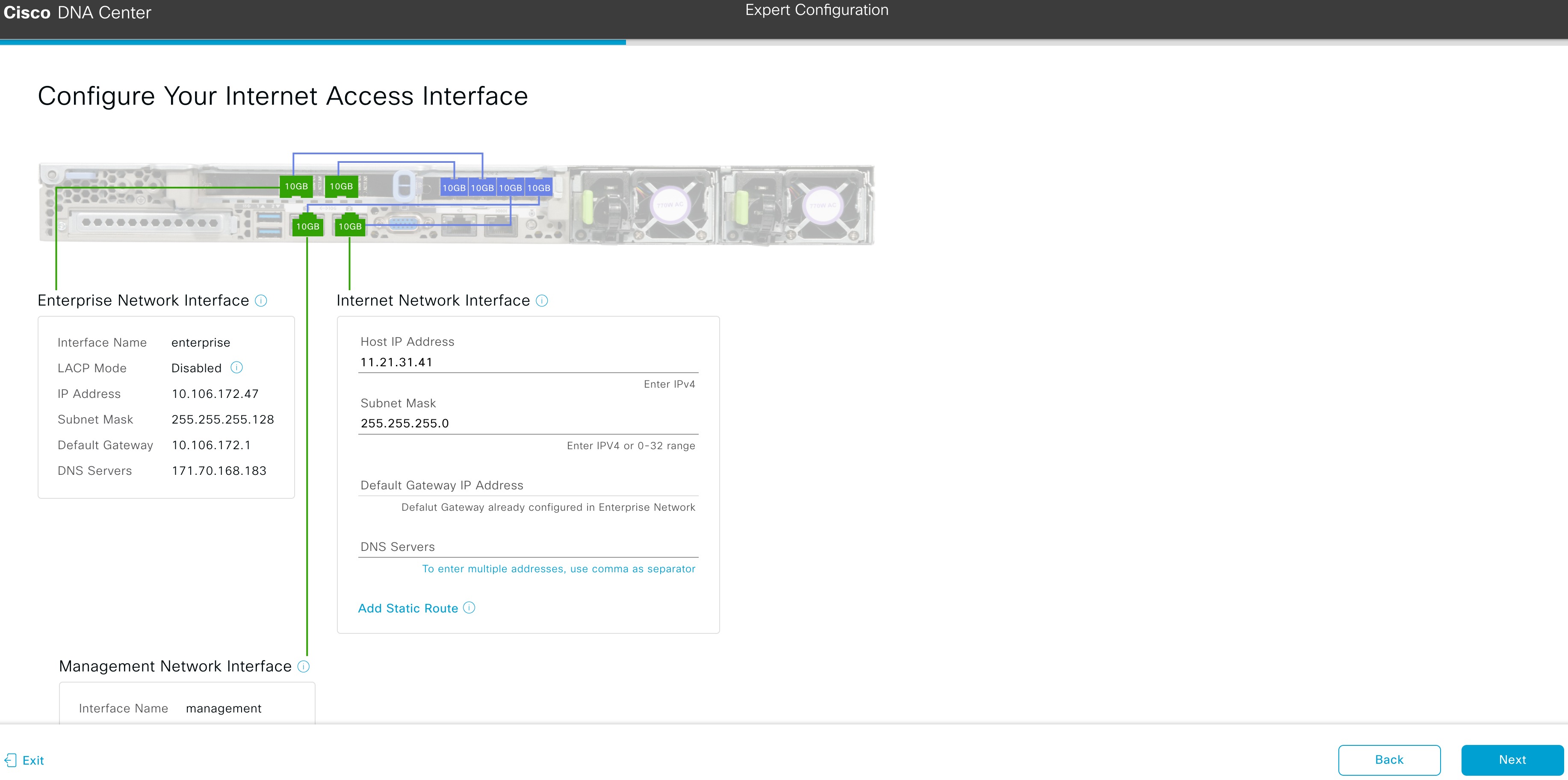
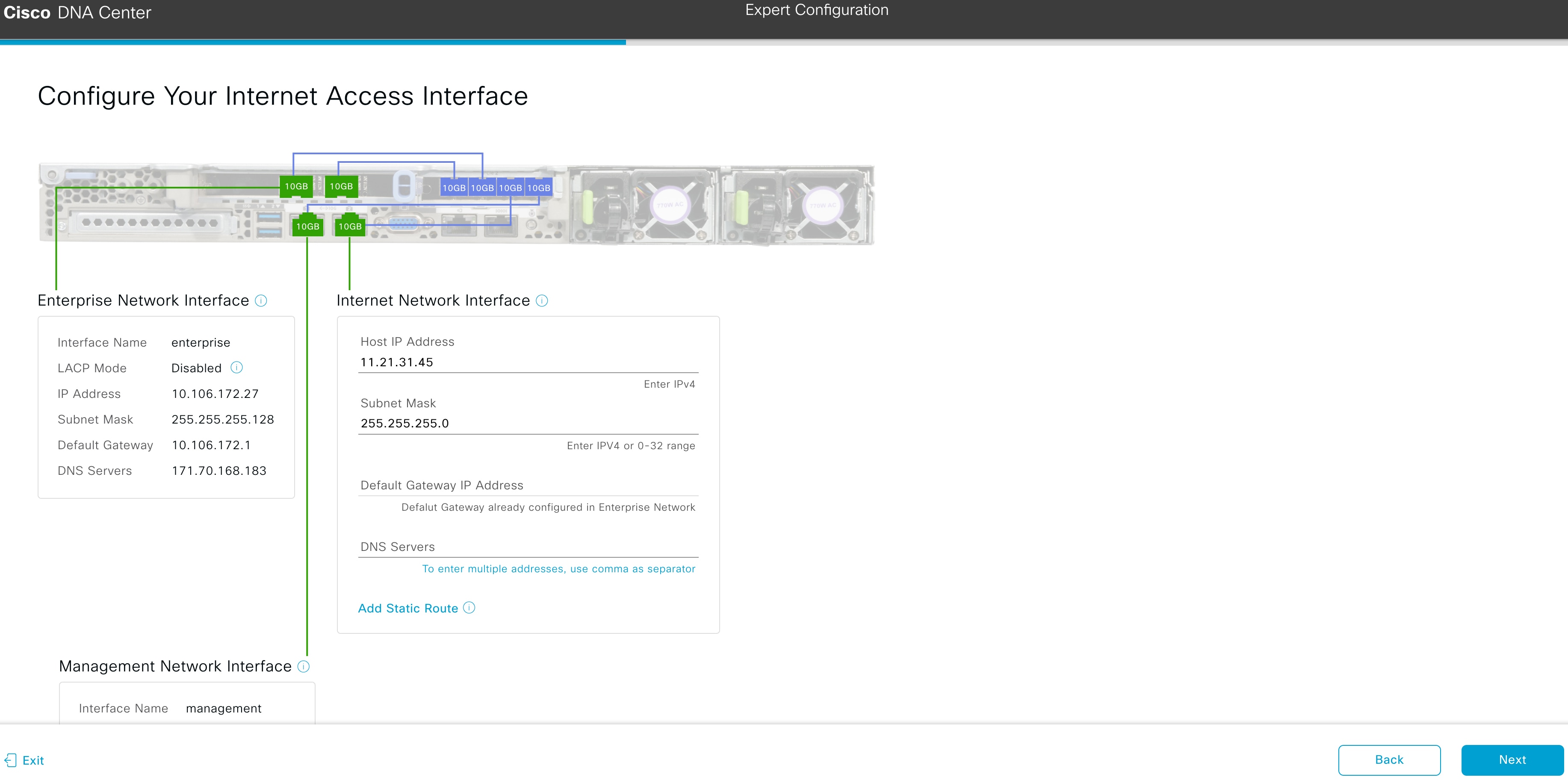
  6. (Optional) Enter configuration values for the Internet Access interface.

    As explained in Interface Cable Connections, this is an optional port used to link the appliance to the Internet when you cannot do so through the Enterprise port. If you chose to configure a dedicated Internet Access interface, enter the information described in the following table. (See Required IP Addresses and Subnets and Required Configuration Information for a more detailed description of the values you need to enter.)

    Note 

    If you opted to configure the Enterprise and Internet Access interfaces on the same port, skip this step and then proceed to Step 2g (which describes how to configure your Intracluster interface).

    Table 3. Primary Node Entries for the Internet Access Port

    Host IP Address field

    Enter the IP address for the Internet Access port.

    Subnet Mask field

    Enter the netmask for the port's IP address. This is required if you enter an IP address.

    Default Gateway IP Address field

    Enter a default gateway IP address to use for the port.

    Important 

    Ensure that you enter a default gateway IP address for at least one of your appliance's interfaces. Otherwise, you will not be able to complete the configuration wizard.

    DNS Servers field

    Enter the IP address of the preferred DNS server. If entering multiple DNS servers, separate the IP addresses in the list with spaces.

    Important 

    For each appliance in your cluster, configure a maximum of three DNS servers. Problems can occur if you configure more than three DNS servers for a node.

    Add Static Route link

    To configure a static route, click this link and then do the following:

    1. Enter the route's network IP prefix, subnet mask, and nexthop IP address.

      To configure additional static routes, click +.

    2. Click Add.

    From here, do one of the following:

    • To close the wizard, click Exit. A popup window appears, indicating that the settings you have entered up to this point will be saved. Click Exit again to confirm that you want to close the wizard. When you restart the wizard and return to this screen, the settings that you entered previously will already be populated.

    • To return to the previous wizard screen, click Back.

    • To proceed to the next wizard screen, click Next.

      The wizard validates the information you have entered, confirms that the port is up, and notifies you of any settings that need to be changed before you can proceed with the wizard. If the settings you have entered are valid and the port is up, the wizard's Configure Your Intracluster Interface screen opens.
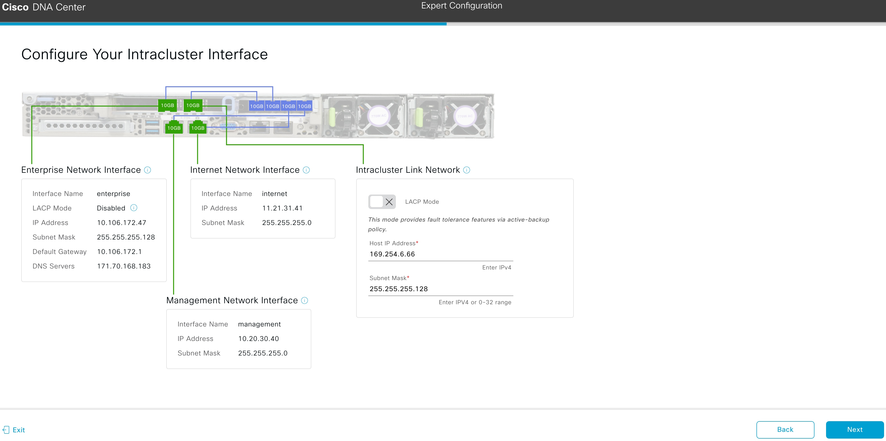
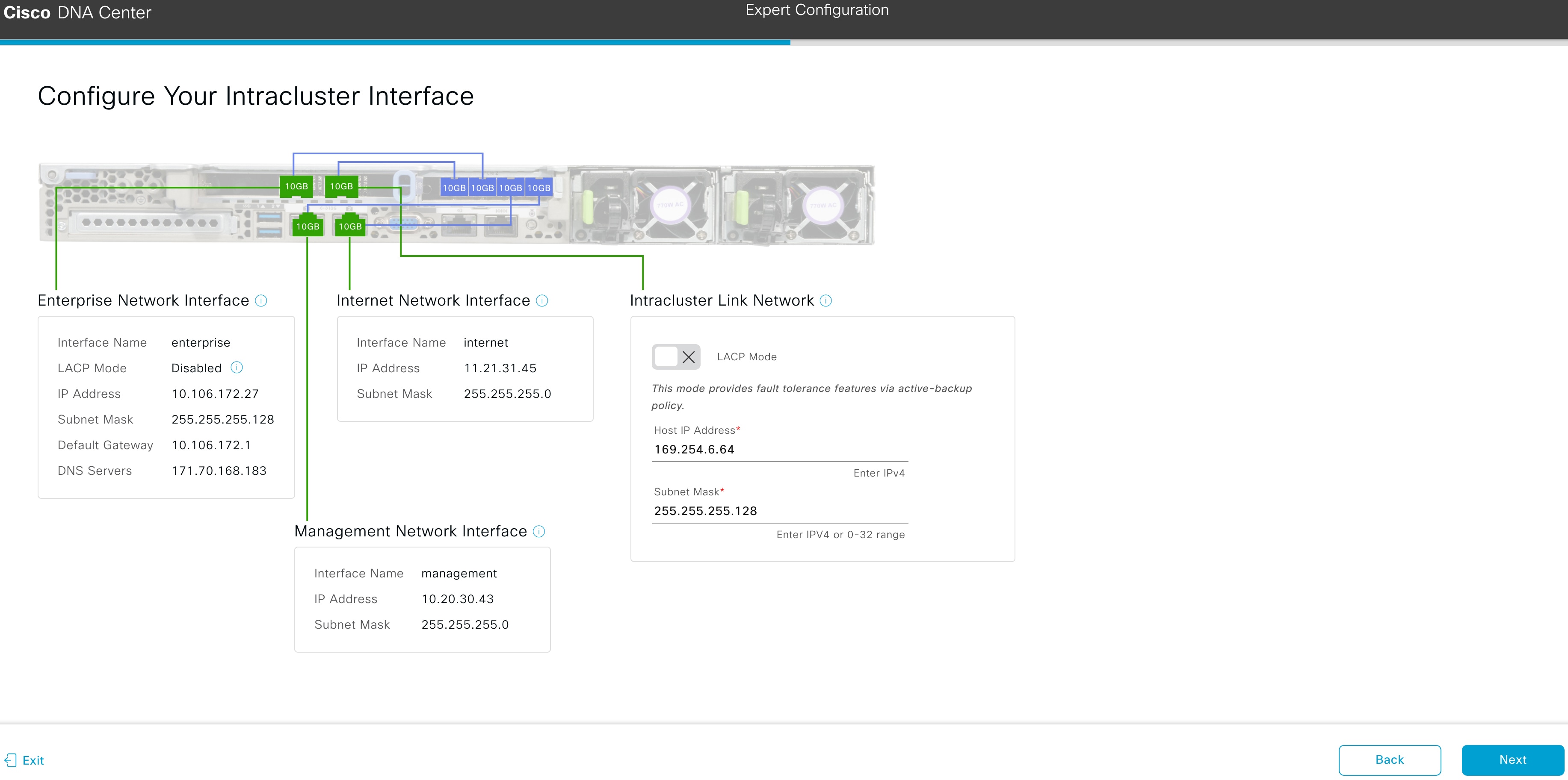
  7. Enter configuration values for your Intracluster interface.

    As explained in Interface Cable Connections, this required port is used to link the appliance to your cluster. See Required IP Addresses and Subnets and Required Configuration Information for a more detailed description of the values you need to enter.

    Table 4. Primary Node Entries for the Intracluster Interface

    LACP Mode slider

    Choose one of the following NIC bonding modes for the Intracluster interface:

    • Active-Backup mode: This mode provides fault tolerance by aggregating two Ethernet interfaces into a single logical channel. When the interface that's currently active goes down, the other interface takes its place and becomes active.

    • LACP mode: This mode aggregates two Ethernet interfaces that share the same speed and duplex settings into a single logical channel. This provides load balancing and higher bandwidth.

    For more information about Cisco DNA Center's implementation of NIC bonding, see NIC Bonding Overview.

    Host IP Address field

    Enter the IP address for the Cluster port. This is required. Note that you cannot change the address of the Cluster port later.

    Subnet Mask field

    Enter the netmask for the port's IP address. This is required.

    From here, do one of the following:

    • To close the wizard, click Exit. A popup window appears, indicating that the settings you have entered up to this point will be saved. Click Exit again to confirm that you want to close the wizard. When you restart the wizard and return to this screen, the settings that you entered previously will already be populated.

    • To return to the previous wizard screen, click Back.

    • To proceed to the next wizard screen, click Next.

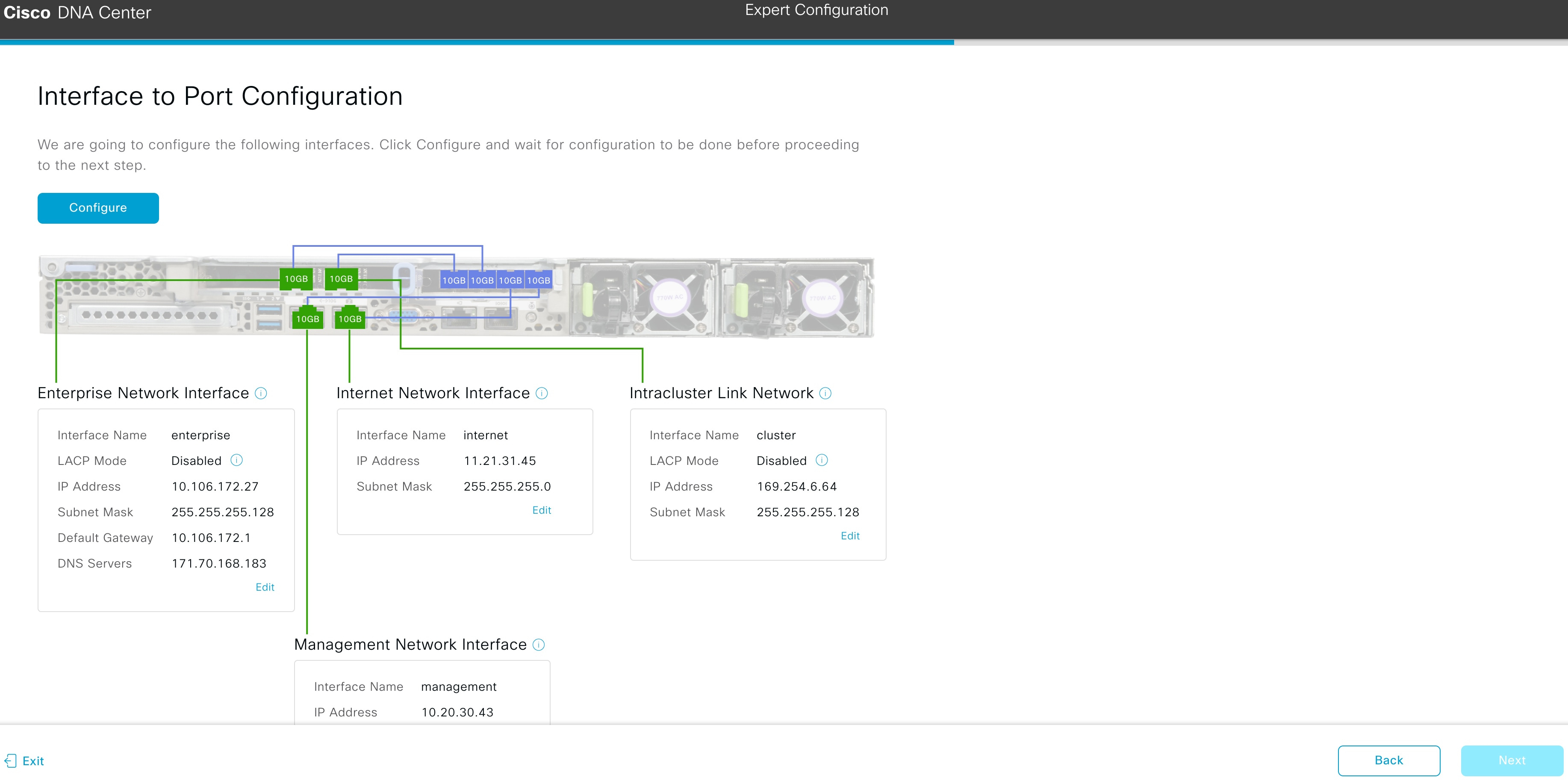
      The wizard validates the information you have entered, confirms that the port is up, and notifies you of any settings that need to be changed before you can proceed with the wizard. If the settings you have entered are valid and the port is up, the wizard's Interface to Port Configuration screen opens.
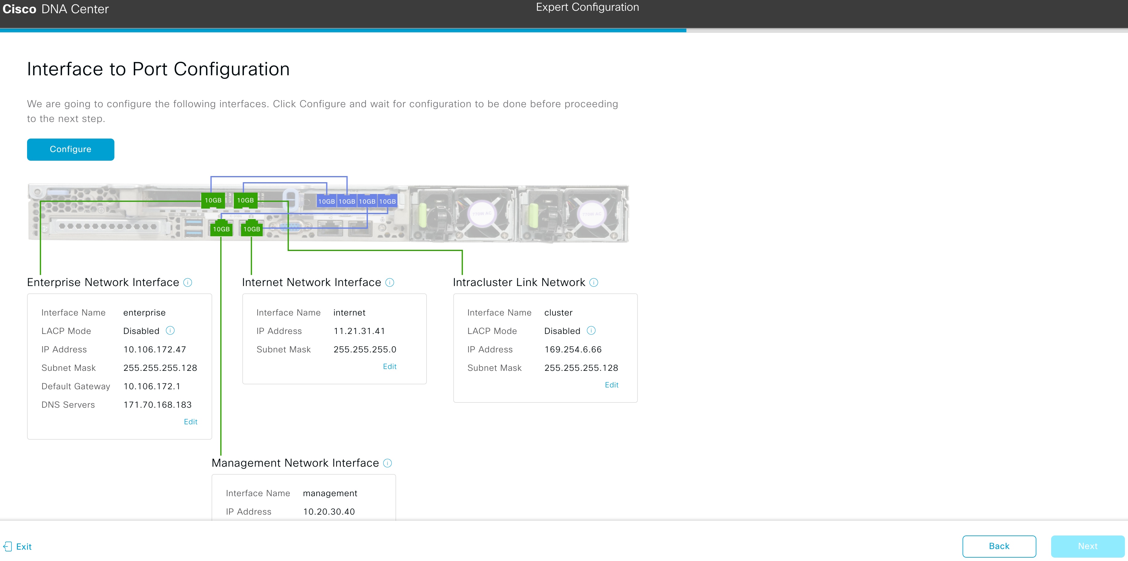
  8. Review the settings that you have entered for the primary node's interfaces.

    If you need to make any changes, click the Edit link for the relevant interface.

  9. When you are happy with the interface settings, click Configure.

  10. After initial interface configuration has completed, click Next.

    The wizard's Configure Proxy Server Information screen opens.
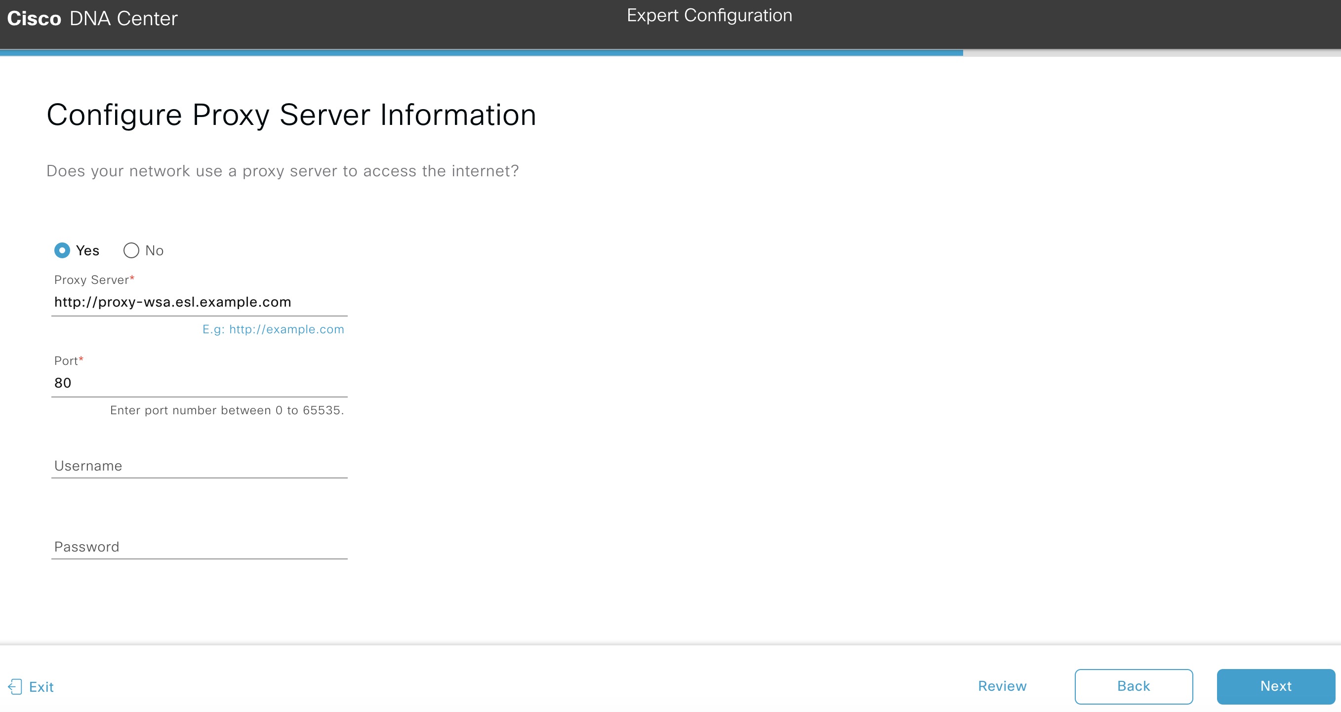
  11. Do one of the following:

    • If your network does not use a proxy server to access the internet, click the No radio button and then click Next.

    • If your network does use a proxy server to access the internet, enter the values described in the following table:

    Table 5. Primary Node Entries for Proxy Server Settings

    Proxy Server field

    Enter the URL or host name of an HTTPS network proxy used to access the Internet.

    Note 
    Connection from Cisco DNA Center to the HTTPS proxy is supported only via HTTP in this release.

    Port field

    Enter the port your appliance used to access the network proxy.

    Username field

    Enter the user name used to access the network proxy. If no proxy login is required, leave this field blank.

    Password field

    Enter the password used to access the network proxy. If no proxy login is required, leave this field blank.

    From here, do one of the following:

    • To close the wizard, click Exit. A popup window appears, indicating that the settings you have entered up to this point will be saved. Click Exit again to confirm that you want to close the wizard. When you restart the wizard and return to this screen, the settings that you entered previously will already be populated.

    • To return to the previous wizard screen, click Back.

    • To proceed to the next wizard screen, click Next.

      The wizard validates the information you have entered and notifies you of any settings that need to be changed before you can proceed with the wizard. If the settings you have entered are valid and the port is up, the wizard's Cluster Details screen opens.
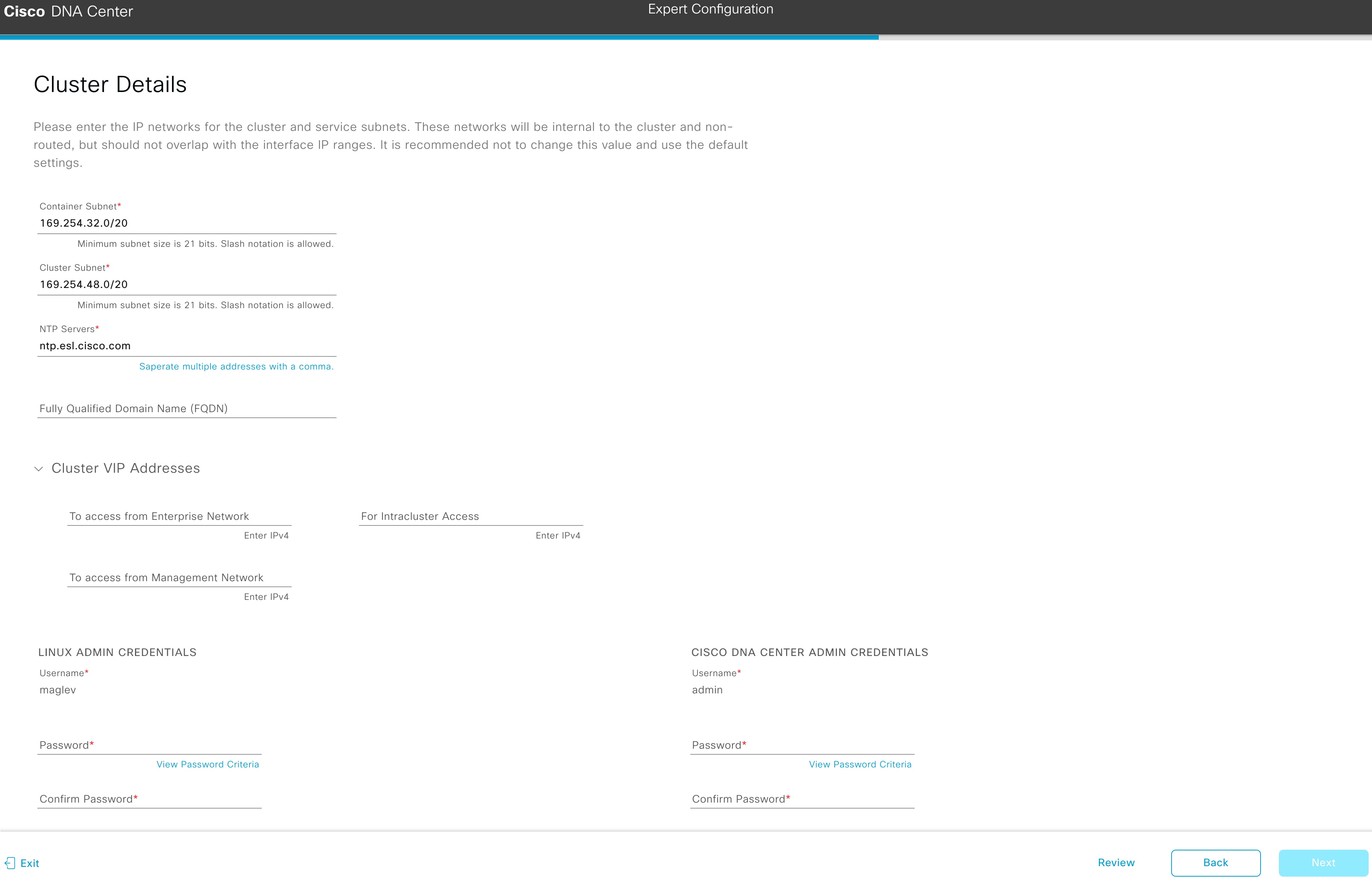
  12. Enter configuration values for your cluster.

    Table 6. Primary Node Entries for Cluster Settings

    Container Subnet field

    A dedicated, non-routed IP subnet that Cisco DNA Center uses to manage internal services. By default, this is already set to 169.254.32.0/20, and we recommend that you use this subnet. If you choose to enter another subnet, ensure that it does not conflict with or overlap any other subnet used by the Cisco DNA Center internal network or an external network. For more information, see the Container Subnet description in Required IP Addresses and Subnets.

    Cluster Subnet field

    A dedicated, non-routed IP subnet that Cisco DNA Center uses to manage internal cluster services. By default, this is already set to 169.254.48.0/20, and we recommend that you use this subnet. If you choose to enter another subnet, ensure that it does not conflict with or overlap any other subnet used by the Cisco DNA Center internal network or an external network. For more information, see the Cluster Subnet description in Required IP Addresses and Subnets.

    NTP Servers field

    Enter one or more NTP server addresses or hostnames, separated by commas. At least one NTP address or hostname is required.

    For a production deployment, Cisco recommends that you configure a minimum of three NTP servers.

    Fully Qualified Domain Name (FQDN) field

    Enter the fully qualified domain name (FQDN) for your cluster. Cisco DNA Center does the following with this hostname:

    • It uses this hostname to access your cluster’s web interface and the Representational State Transfer (REST) APIs used by devices in the enterprise network that Cisco DNA Center manages.

    • In the Subject Alternative Name (SAN) field of Cisco DNA Center certificates, it uses the FQDN to the define the Plug and Play server that should be used for device provisioning.

    Cluster VIP Addresses

    To access from Enterprise Network, To access from Management Network, For Internet Access, and For Intracluster Access fields

    Note 

    If you configured the Management or Internet Access interface on the same port as the Enterprise interface, its corresponding field is not displayed in this section.

    Enter the virtual IP address that will be used for traffic between the cluster and the interfaces that you have configured on your primary node. This is required for both three-node clusters and single-node clusters that will be converted into a three-node cluster in the future. If you have a single-node cluster setup and plan to stick with it, you can leave the fields in this section blank.

    Important 

    You must enter one virtual IP address for each configured network interface. You will not be able to complete the wizard unless you do so. This address is tied to the cluster link's status, which must be in the UP state.

    Linux Admin Credentials

    Password and Confirm Password fields

    Enter and then confirm the password for the maglev user.

    Cisco DNA Center Admin Credentials

    Password and Confirm Password fields

    Enter and then confirm the password for the default admin superuser, used to log in to Cisco DNA Center for the first time.

    From here, do one of the following:

    • To close the wizard, click Exit. A popup window appears, indicating that the settings you have entered up to this point will be saved. Click Exit again to confirm that you want to close the wizard. When you restart the wizard and return to this screen, the settings that you entered previously will already be populated.

    • To return to the previous wizard screen, click Back.

    • To proceed to the next wizard screen, click Next.

      The wizard validates the information you have entered and notifies you of any settings that need to be changed before you can proceed with the wizard. If the settings you have entered are valid, the wizard's Summary screen opens.
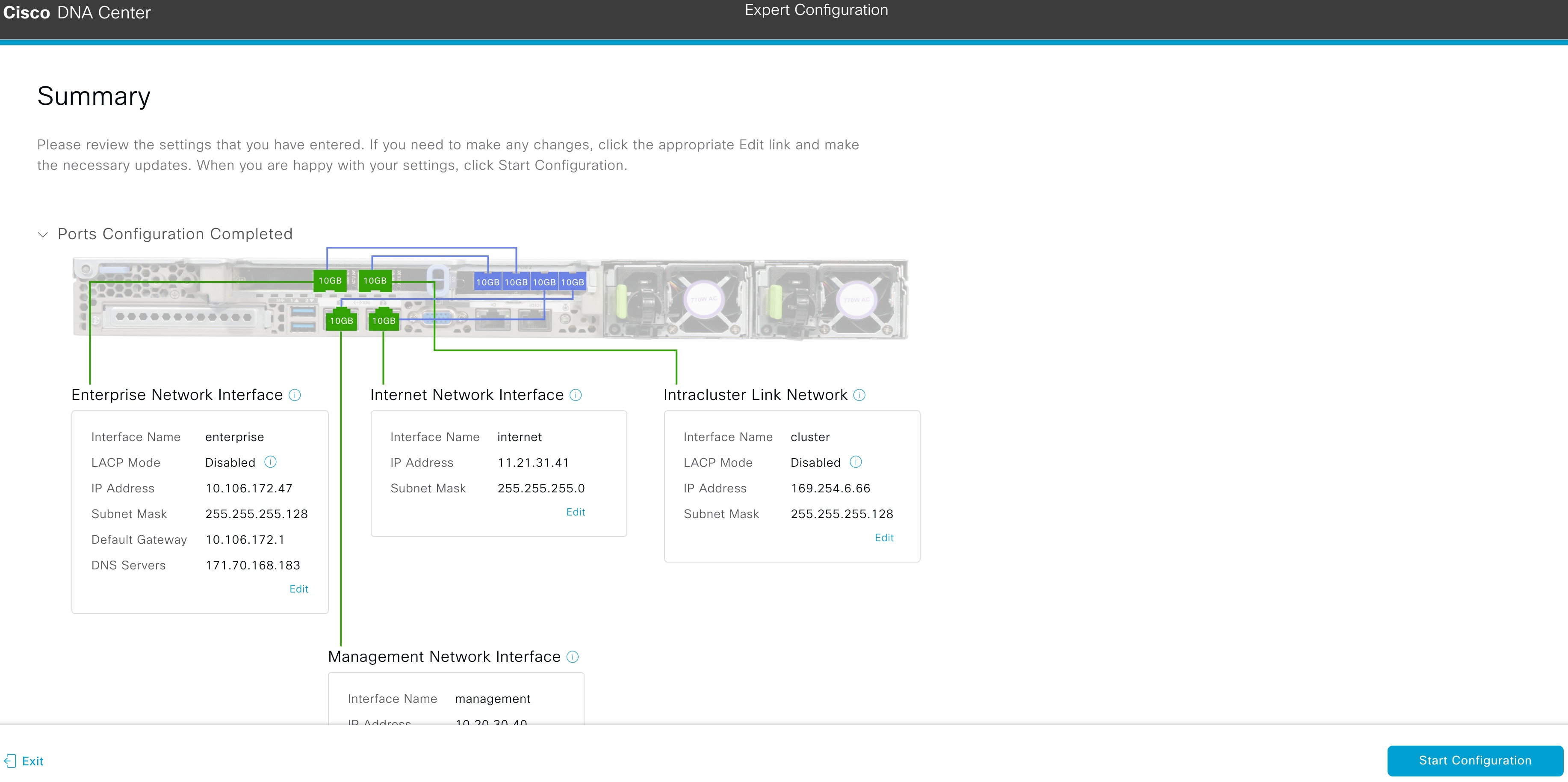
  13. Review all of the settings that you have entered while completing the wizard. If necessary, click the appropriate Edit link to open the wizard screen in which you want to make updates.

  14. To complete the configuration of your Cisco DNA Center appliance, click Start Configuration.

    The wizard screen continuously updates during the process, indicating the tasks that are currently being completed and their progress, as well as any errors that have occurred. To save a local copy of this information as a text file, click the download icon.
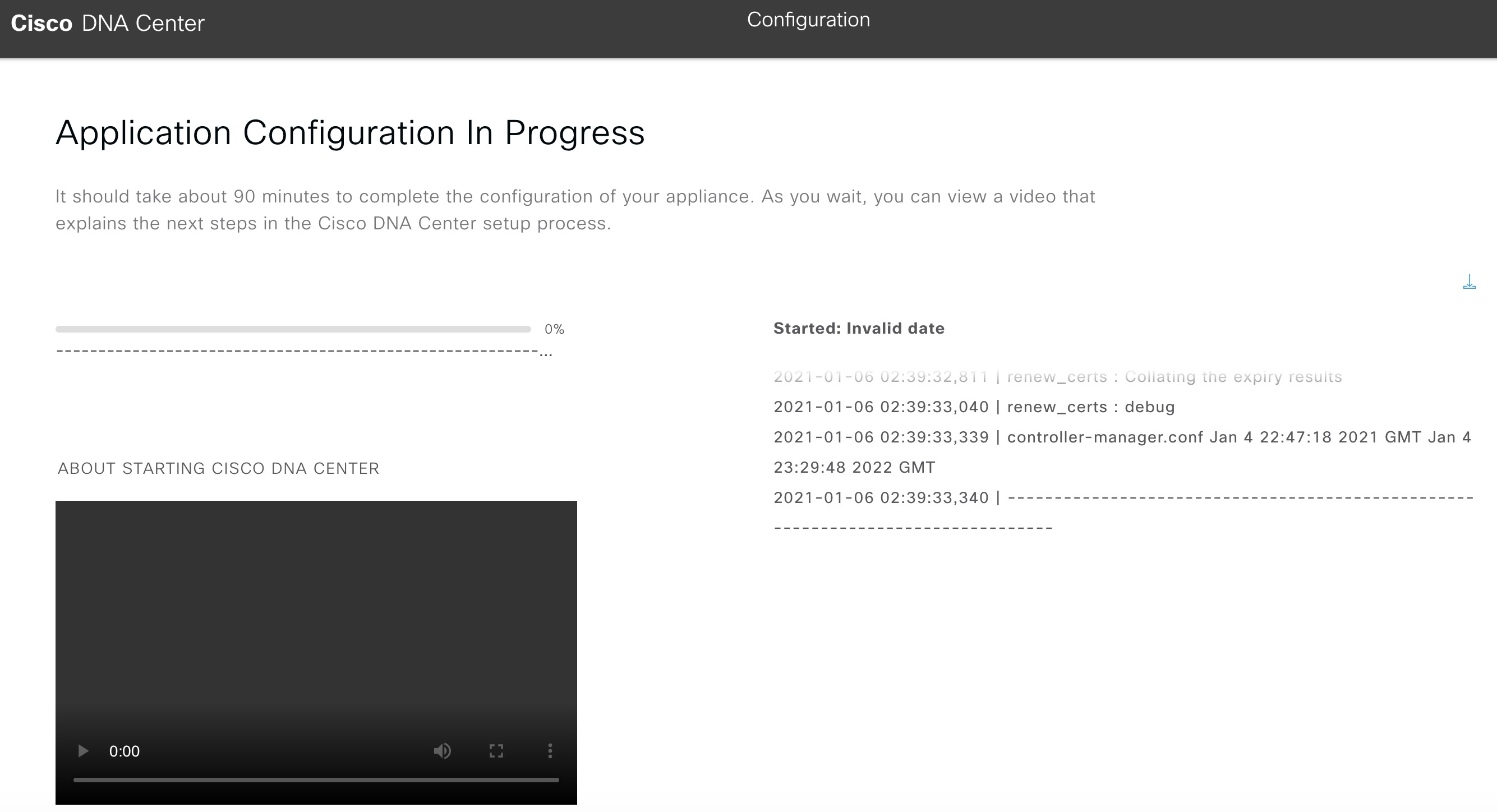
    While the configuration process is taking place, you can also watch a quick video that describes how to get started using Cisco DNA Center.


What to do next

When this task is complete:

Configure a Secondary Node Using the Expert Configuration Wizard

Perform the following steps to configure the second and third nodes in the cluster using the Expert Configuration wizard.


Important

  • In order to build a three-node cluster, the same version of the System package must be installed on your three Cisco DNA Center appliances. Otherwise, unexpected behavior and possible downtime can occur.

  • The following second generation Cisco DNA Center appliances support configuration using the Expert Configuration wizard:

    • 44-core appliance: Cisco part number DN2-HW-APL

    • 44-core promotional appliance: Cisco part number DN2-HW-APL-U

    • 56-core appliance: Cisco part number DN2-HW-APL-L

    • 56-core promotional appliance: Cisco part number DN2-HW-APL-L-U

    The first generation 44-core Cisco DNA Center appliance (Cisco part number DN1-HW-APL) cannot be configured using this wizard.


Note

Ensure that all of the IP addresses you enter while completing this procedure are valid IPv4 addresses with valid IPv4 netmasks. Also make sure that the addresses and their corresponding subnets do not overlap. Service communication issues can result if they do.


When joining each new secondary nodes to the cluster, you must specify the first appliance in the cluster as the primary node. Note the following when joining secondary nodes to a cluster:

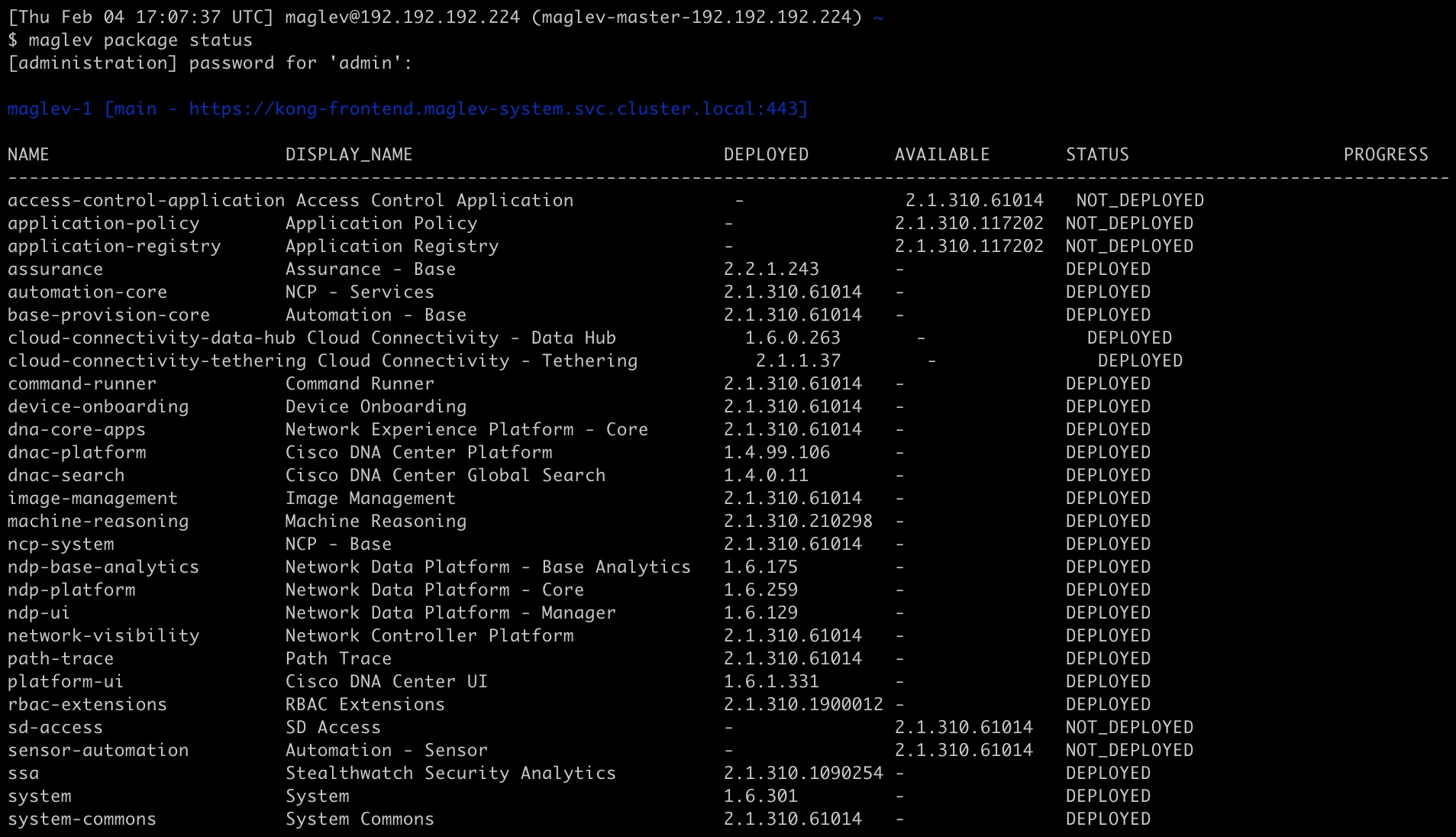
  • Before adding a new node to the cluster, be sure that all installed packages are deployed on the primary node. You can check this by using Secure Shell to log in to the primary node's Cisco DNA Center Management port as the Linux User (maglev) and then running the command maglev package status. All installed packages should appear in the command output as DEPLOYED. In the following example, a few packages were not installed, such as the application-policy and sd-access packages. They are the only packages whose status is NOT_DEPLOYED. Your package status should look similar to this before configuring a secondary node.

  • Be sure to join only a single node to the cluster at a time. Do not attempt to add multiple nodes at the same time, as doing so will result in unpredictable behavior.

  • Expect some service downtime during the cluster attachment process for each secondary node. Services will need to be redistributed across the nodes and the cluster will be down for periods of time during that process.

Before you begin

Ensure that you:

  • Installed the Cisco DNA Center software image onto your appliance, as described in Reimage the Appliance.


    Important

    This is only applicable if you are going to configure a promotional appliance, because the Cisco DNA Center software image is not preinstalled on the following appliances:

    • 44-core promotional appliance (Cisco part number DN2-HW-APL-U)

    • 56-core promotional appliance: (Cisco part number DN2-HW-APL-L-U)


  • Configured the first appliance in the cluster, following the steps in Configure the Primary Node Using the Expert Configuration Wizard.

  • Collected all of the information called for in Required IP Addresses and Subnets and Required Configuration Information.

  • Installed the second and third appliances as described in Appliance Installation Workflow.

  • Have done the following:

    1. Ran the maglev package status command on the first appliance.

      You can also access this information from the Cisco DNA Center GUI by clicking the Help icon () and choosing About > Packages.

    2. Contacted the Cisco TAC, gave them the output of this command, and asked them to point you to the ISO that you should install on your second and third appliances.

  • Configured Cisco IMC browser access on both secondary nodes as described in Enable Browser Access to Cisco IMC.

  • Checked that both secondary nodes' ports and the switches they use are properly configured, as described in Execute Preconfiguration Checks.

  • Are using a compatible browser. For a list of compatible browsers, see the Release Notes for the version of Cisco DNA Center you are installing.

  • Enabled ICMP on the firewall between Cisco DNA Center and both the default gateway and the DNS server you specify in the following procedure. The wizard uses ping to verify the gateway and DNS server you specify. This ping might get blocked if a firewall is in place and ICMP is not enabled on that firewall. When this happens, you will not be able to complete the wizard.

Procedure


Step 1

Start the Expert Configuration wizard:

  1. Point your browser to the Cisco IMC IP address you set during the Cisco IMC GUI configuration you performed, then log in to the Cisco IMC GUI as the Cisco IMC user (see Enable Browser Access to Cisco Integrated Management Controller).

    After successful login, the appliance displays the Cisco Integrated Management Controller Chassis Summary window, with a blue link menu at the upper right, as shown below.
  2. From the blue link menu, choose Launch KVM and then select either Java based KVM or HTML based KVM. If you select the Java-based KVM, you will need to launch the Java startup file from your browser or file manager in order to view the KVM console in its own window. If you select the HMTL-based KVM, it will launch the KVM console in a separate browser window or tab automatically.

    Irrespective of the KVM type you choose, use the KVM console to monitor the progress of the configuration and respond to Maglev Configuration Wizard prompts.

  3. With the KVM displayed, reboot the appliance by making one of the following selections:

    • In the main Cisco IMC GUI browser window: Choose Host Power > Power Cycle. Then switch to the KVM console to continue.

    • In the KVM console: Choose Power > Power Cycle System (cold boot).

    If asked to confirm your choice to reboot the appliance, click OK.

    After displaying reboot messages, the KVM console displays the Maglev Configuration wizard welcome screen.

    Note the URL listed in the Web Installation field.

  4. Open this URL to bring up the Appliance Configuration screen.

  5. Click the Expert Configuration radio button, then click Start.

    The Expert Configuration Overview slider opens. Click > to view a summary of the tasks that the wizard will help you complete.

  6. Click Start Workflow to start the wizard.

    The Appliance Interface Overview screen opens, providing a description of the four appliance interfaces that you can configure.

    At a minimum, you must configure the interfaces on your appliance's Enterprise and Cluster ports, as they are required for Cisco DNA Center functionality. If the wizard fails to display either or both of these ports during the course of configuration, they may be non-functional or disabled. If you discover that they are non-functional, choose Exit to exit the wizard immediately. Be sure you have completed all of the steps provided in Execute Preconfiguration Checks before resuming configuration or contacting the Cisco Technical Assistance Center (TAC).

Step 2

Complete the Expert Configuration wizard:

  1. Click Next.

    The Will this appliance join a cluster? screen opens.

  2. Click the Yes radio button, then click Next.

    The How would you like to set up your appliance interfaces? screen opens.

  3. Indicate whether you want to configure dedicated Management and Internet Access interfaces, then click Next.

    The Configure Your Enterprise Network Interface screen opens.

  4. Enter configuration values for the Enterprise interface.

    As explained in Interface Cable Connections, this is a required interface used to link the appliance to the enterprise network. See Required IP Addresses and Subnets and Required Configuration Information for a more detailed description of the values you need to enter.

    Note 
    • If you opted to configure the Enterprise and Internet Access interfaces on the same port, complete this step and then proceed to Step 2e (which describes how to configure your Management interface).

    • If you opted to configure the Enterprise and Management interfaces on the same port, complete this step and then skip ahead to Step 2f (which describes how to configure your Internet Access interface).

    • If you opted to configure the Enterprise, Management, and Internet Access interfaces on the same port, complete this step and then skip ahead to Step 2g (which describes how to configure your Intracluster interface).

    Table 7. Secondary Node Entries for the Enterprise Interface

    LACP Mode slider

    Choose one of the following network interface controller (NIC) bonding modes for the Enterprise interface:

    • Active-Backup mode: This mode provides fault tolerance by aggregating two Ethernet interfaces into a single logical channel. When the interface that's currently active goes down, the other interface takes its place and becomes active.

    • LACP mode: This mode aggregates two Ethernet interfaces that share the same speed and duplex settings into a single logical channel. This provides load balancing and higher bandwidth.

    For more information about Cisco DNA Center's implementation of NIC bonding, see NIC Bonding Overview.

    Host IP Address field

    Enter the IP address for the Enterprise port. This is required.

    Subnet Mask field

    Enter the netmask for the port's IP address. This is required.

    Default Gateway IP Address field

    Enter a default gateway IP address to use for the port.

    Important 

    Ensure that you enter a default gateway IP address for at least one of your appliance's interfaces. Otherwise, you will not be able to complete the configuration wizard.

    Note 

    You designated this interface to use the default gateway assigned to it by a DHCP server. Complete the following steps to specify a different gateway:

    1. Delete the IP address that is currently listed in this field and then click Exit.

      This will bring you back to the first wizard screen.

    2. Return to the Enterprise port's wizard screen and enter the gateway IP address you want to use.

    DNS Servers field

    Enter the IP address of the preferred DNS server. If entering multiple DNS servers, separate the IP addresses in the list with commas.

    Important 

    For each appliance in your cluster, configure a maximum of three DNS servers. Problems can occur if you configure more than three DNS servers for a node.

    Add Static Route link

    To configure a static route, click this link and then do the following:

    1. Enter the route's network IP prefix, subnet mask, and nexthop IP address.

      To configure additional static routes, click +.

    2. Click Add.

    From here, do one of the following:

    • To close the wizard, click Exit. A popup window appears, indicating that the settings you have entered up to this point will be saved. Click Exit again to confirm that you want to close the wizard. When you restart the wizard and return to this screen, the settings that you entered previously will already be populated.

    • To return to the previous wizard screen, click Back.

    • To proceed to the next wizard screen, click Next.

      The wizard validates the information you have entered, confirms that the port is up, and notifies you of any settings that need to be changed before you can proceed with the wizard. If the settings you have entered are valid and the port is up, the wizard's Configure Your Management Network Interface screen opens.

  5. (Optional) Enter configuration values for the Management port.

    As explained in Interface Cable Connections, this port is used to access the Cisco DNA Center GUI from your management network. If you chose to configure a dedicated Management interface, enter the information described in the following table. (See Required IP Addresses and Subnets and Required Configuration Information for a more detailed description of the values you need to enter.)

    Note 
    • If you opted to configure the Enterprise and Management interfaces on the same port, skip this step and proceed to Step 2f (which describes how to configure your Internet Access interface).

    • If you opted to configure the Enterprise, Management, and Internet Access interfaces on the same port, skip this step and proceed to Step 2g (which describes how to configure your Intracluster interface).

    Table 8. Secondary Node Entries for the Management Port

    Host IP Address field

    Enter the IP address for the Management port. This is required.

    Subnet Mask field

    Enter the netmask for the port's IP address. This is required.

    Default Gateway IP Address field

    Enter a default gateway IP address to use for the port.

    Important 

    Ensure that you enter a default gateway IP address for at least one of your appliance's interfaces. Otherwise, you will not be able to complete the configuration wizard.

    DNS Servers field

    Enter the IP address of the preferred DNS server. If entering multiple DNS servers, separate the IP addresses in the list with spaces.

    Important 
    • For NTP, ensure port 123 (UDP) is open between Cisco DNA Center and your NTP server.

    • For each appliance in your cluster, configure a maximum of three DNS servers. Problems can occur if you configure more than three DNS servers for a node.

    Add Static Route link

    To configure a static route, click this link and then do the following:

    1. Enter the route's network IP prefix, subnet mask, and nexthop IP address.

      To configure additional static routes, click +.

    2. Click Add.

    From here, do one of the following:

    • To close the wizard, click Exit. A popup window appears, indicating that the settings you have entered up to this point will be saved. Click Exit again to confirm that you want to close the wizard. When you restart the wizard and return to this screen, the settings that you entered previously will already be populated.

    • To return to the previous wizard screen, click Back.

    • To proceed to the next wizard screen, click Next.

      The wizard validates the information you have entered, confirms that the port is up, and notifies you of any settings that need to be changed before you can proceed with the wizard. If the settings you have entered are valid and the port is up, the wizard's Configure Your Internet Access Interface screen opens.

  6. (Optional) Enter configuration values for the Internet Access interface.

    As explained in Interface Cable Connections, this is an optional port used to link the appliance to the Internet when you cannot do so through the Enterprise port. If you chose to configure a dedicated Internet Access interface, enter the information described in the following table. (See Required IP Addresses and Subnets and Required Configuration Information for a more detailed description of the values you need to enter.)

    Note 

    If you opted to configure the Enterprise and Internet Access interfaces on the same port, skip this step and then proceed to Step 2g (which describes how to configure your Intracluster interface).

    Table 9. Secondary Node Entries for the Internet Access Port

    Host IP Address field

    Enter the IP address for the Internet Access port.

    Subnet Mask field

    Enter the netmask for the port's IP address. This is required if you enter an IP address.

    Default Gateway IP Address field

    Enter a default gateway IP address to use for the port.

    Important 

    Ensure that you enter a default gateway IP address for at least one of your appliance's interfaces. Otherwise, you will not be able to complete the configuration wizard.

    DNS Servers field

    Enter the IP address of the preferred DNS server. If entering multiple DNS servers, separate the IP addresses in the list with spaces.

    Important 

    For each appliance in your cluster, configure a maximum of three DNS servers. Problems can occur if you configure more than three DNS servers for a node.

    Add Static Route link

    To configure a static route, click this link and then do the following:

    1. Enter the route's network IP prefix, subnet mask, and nexthop IP address.

      To configure additional static routes, click +.

    2. Click Add.

    From here, do one of the following:

    • To close the wizard, click Exit. A popup window appears, indicating that the settings you have entered up to this point will be saved. Click Exit again to confirm that you want to close the wizard. When you restart the wizard and return to this screen, the settings that you entered previously will already be populated.

    • To return to the previous wizard screen, click Back.

    • To proceed to the next wizard screen, click Next.

      The wizard validates the information you have entered, confirms that the port is up, and notifies you of any settings that need to be changed before you can proceed with the wizard. If the settings you have entered are valid and the port is up, the wizard's Configure Your Intracluster Interface screen opens.

  7. Enter configuration values for your Intracluster interface.

    As explained in Interface Cable Connections, this required port is used to link the appliance to your cluster. See Required IP Addresses and Subnets and Required Configuration Information for a more detailed description of the values you need to enter.

    Table 10. Secondary Node Entries for the Intracluster Interface

    LACP Mode slider

    Choose one of the following NIC bonding modes for the Intracluster interface:

    • Active-Backup mode: This mode provides fault tolerance by aggregating two Ethernet interfaces into a single logical channel. When the interface that's currently active goes down, the other interface takes its place and becomes active.

    • LACP mode: This mode aggregates two Ethernet interfaces that share the same speed and duplex settings into a single logical channel. This provides load balancing and higher bandwidth.

    For more information about Cisco DNA Center's implementation of NIC bonding, see NIC Bonding Overview.

    Host IP Address field

    Enter the IP address for the Cluster port. This is required. Note that you cannot change the address of the Cluster port later.

    Subnet Mask field

    Enter the netmask for the port's IP address. This is required.

    From here, do one of the following:

    • To close the wizard, click Exit. A popup window appears, indicating that the settings you have entered up to this point will be saved. Click Exit again to confirm that you want to close the wizard. When you restart the wizard and return to this screen, the settings that you entered previously will already be populated.

    • To return to the previous wizard screen, click Back.

    • To proceed to the next wizard screen, click Next.

      The wizard validates the information you have entered, confirms that the port is up, and notifies you of any settings that need to be changed before you can proceed with the wizard. If the settings you have entered are valid and the port is up, the wizard's Interface to Port Configuration screen opens.

  8. Review the settings that you have entered for the secondary node's interfaces.

    If you need to make any changes, click the Edit link for the relevant interface to return to its wizard screen.

  9. When you are happy with the interface settings, click Configure.

  10. After initial interface configuration has completed, click Next.

    The Configure Proxy Server Information screen opens.

  11. Do one of the following:

    • If your network does not use a proxy server to access the internet, click the No radio button and then click Next.

    • If your network does use a proxy server to access the internet, enter the values described in the following table:

    Table 11. Secondary Node Entries for Proxy Server Settings

    Proxy Server field

    Enter the URL or host name of an HTTPS network proxy used to access the Internet.

    Note 
    Connection from Cisco DNA Center to the HTTPS proxy is supported only via HTTP in this release.

    Port field

    Enter the port your appliance used to access the network proxy.

    Username field

    Enter the user name used to access the network proxy. If no proxy login is required, leave this field blank.

    Password field

    Enter the password used to access the network proxy. If no proxy login is required, leave this field blank.

    From here, do one of the following:

    • To close the wizard, click Exit. A popup window appears, indicating that the settings you have entered up to this point will be saved. Click Exit again to confirm that you want to close the wizard. When you restart the wizard and return to this screen, the settings that you entered previously will already be populated.

    • To return to the previous wizard screen, click Back.

    • To proceed to the next wizard screen, click Next.

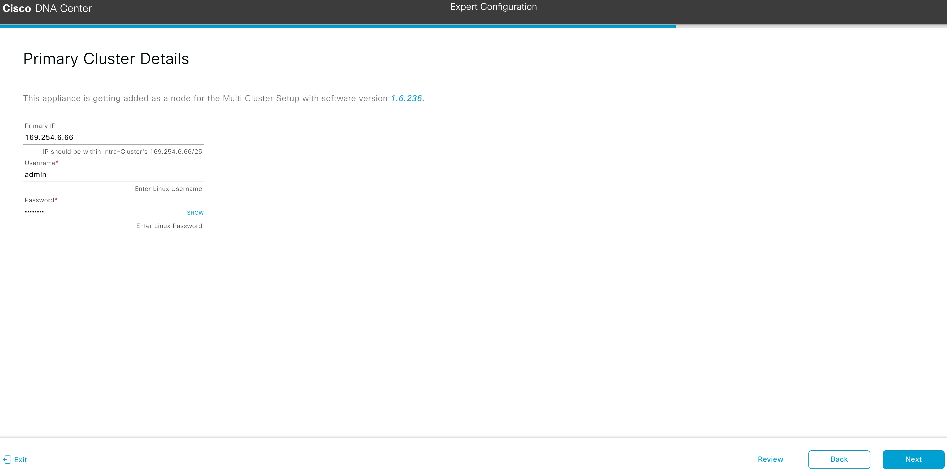
      The wizard validates the information you have entered and notifies you of any settings that need to be changed before you can proceed with the wizard. If the settings you have entered are valid, the wizard's Primary Cluster Details screen opens.

  12. To establish a connection with your cluster's primary node, enter its IP address and login credentials, and then click Next.

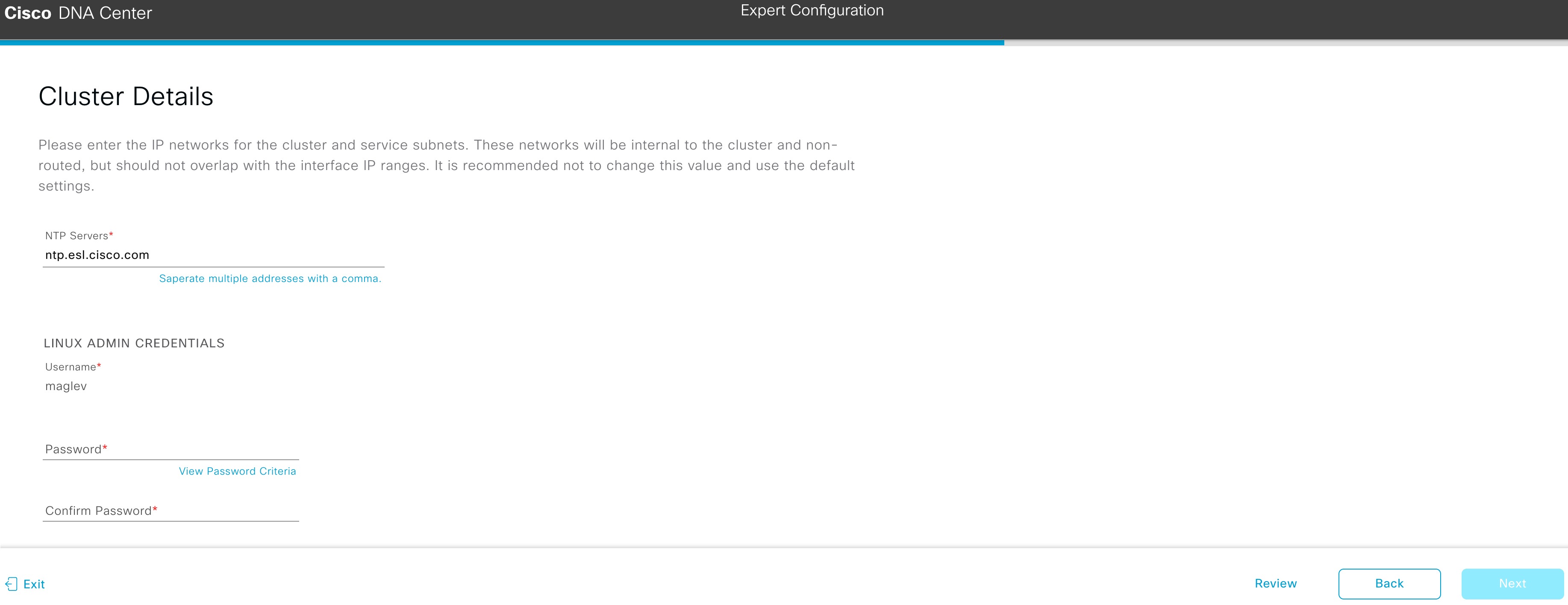
    The Cluster Details screen opens.

  13. Enter configuration values for your cluster.

    Table 12. Secondary Node Entries for Cluster Settings

    NTP Servers field

    Enter one or more NTP server addresses or hostnames, separated by commas. At least one NTP address or hostname is required.

    For a production deployment, Cisco recommends that you configure a minimum of three NTP servers.

    Linux Admin Credentials

    Password and Confirm Password fields

    Enter and then confirm the password for the maglev user.

    From here, do one of the following:

    • To close the wizard, click Exit. A popup window appears, indicating that the settings you have entered up to this point will be saved. Click Exit again to confirm that you want to close the wizard. When you restart the wizard and return to this screen, the settings that you entered previously will already be populated.

    • To return to the previous wizard screen, click Back.

    • To proceed to the next wizard screen, click Next.

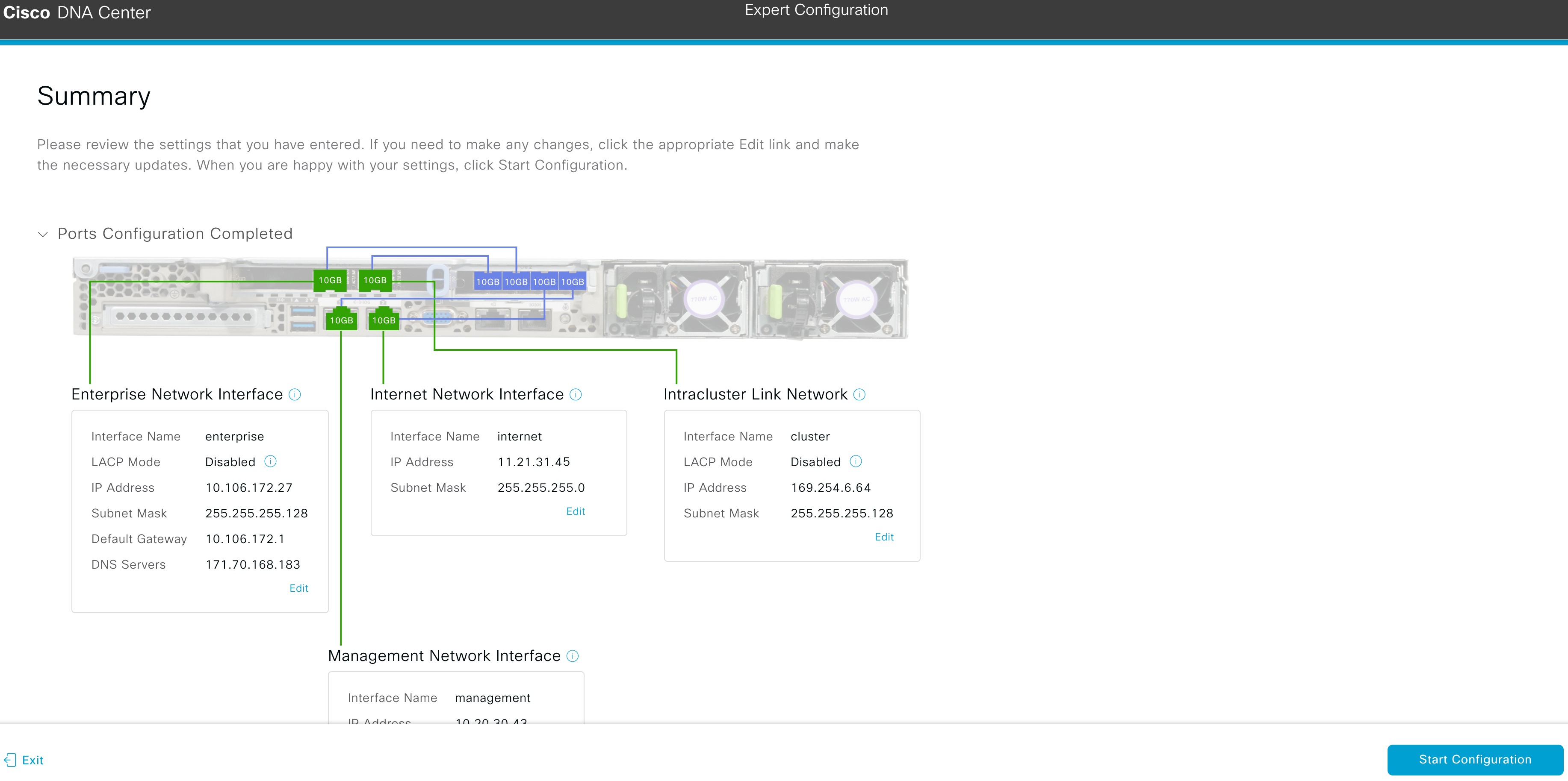
      The wizard validates the information you have entered, confirms that the port is up, and notifies you of any settings that need to be changed before you can proceed with the wizard. If the settings you have entered are valid, the wizard's Summary screen opens.

  14. Review all of the settings that you have entered while completing the wizard. If necessary, click the appropriate Edit link to open the wizard screen in which you want to make updates.

  15. To complete the configuration of your Cisco DNA Center appliance, click Start Configuration.

    The wizard screen continuously updates during the process, indicating the tasks that are currently being completed and their progress, as well as any errors that have occurred. To save a local copy of this information as a text file, click the download icon.

    While the configuration process is taking place, you can also watch a quick video that describes how to get started using Cisco DNA Center.


What to do next

When this task is complete:

  • If you have an additional appliance to deploy as the third and final node in the cluster, repeat this procedure.

  • If you are finished adding nodes to the cluster, continue by performing first-time setup: First-Time Setup Workflow.

Generate a Linux Password

When configuring your appliance, you have the option of using a Linux password that is generated by Cisco DNA Center. To generate this password, complete the following steps:

Procedure


Step 1

From the wizard's Cluster Setting screen, click the Click here to Generate New Password link.

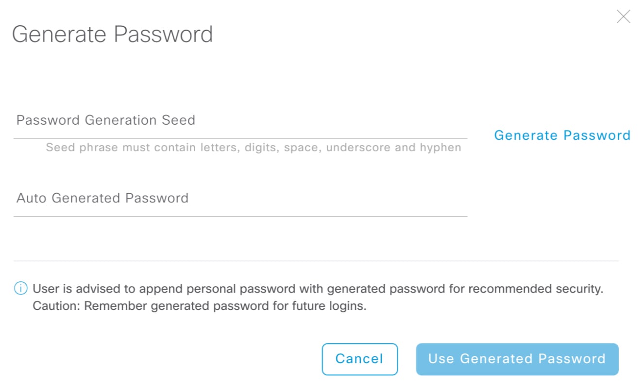
The Generate Password dialog box opens.

Step 2

In the Password Generation Seed field, enter a seed phrase.

The seed phrase can contain letters, numbers, spaces, underscores, and hyphens.

Step 3

Click the Generate Password link.

In the Auto Generated Password field, the seed phrase appears as part of a random and secure password that Cisco DNA Center generates. You can either use this password as is or make any desired changes.

Step 4

When you are happy with the password, click Use Generated Password.

Make sure to save this password for future logins.


Upgrade to the Latest Cisco DNA Center Release

For information about upgrading your current release of Cisco DNA Center, see the Cisco DNA Center Upgrade Guide.