Overview of Cisco Crosswork Optimization Engine

This is a post-installation document intended to cover the steps required to get up and running with Cisco Crosswork Optimization Engine and start using the user interface (UI). For administrative tasks including device and user management, see the Cisco Crosswork Infrastructure and Applications Administration Guide.

Audience

This guide is for experienced network administrators who want to use Cisco Crosswork Optimization Engine in their network. This guide assumes that you are experienced and familiar with using the following technologies:

  • Networking technologies and protocols (BGP-LS, IGP (OSPF and IS-IS), PCEP, model-driven telemetry, and so on)

  • Traffic Engineering (TE) Tunnels:

    • RSVP-TE tunnel provisioning

    • Segment Routing Traffic Engineering (SR-TE) policy provisioning

  • Cisco Segment Routing Path Computation Element (SR-PCE)

  • Point to Multi Point Tree (Tree-SID) on Topology Map

  • Flexible Algorithms

Overview of Cisco Crosswork Optimization Engine

Crosswork Optimization Engine is part of the Cisco Crosswork Network Automation suite of products and provides the ability to preserve network intent with proactive network monitoring, network visualization, and closed loop automation. It also provides real-time network optimization allowing operators to effectively maximize network utilization and increase service velocity.

Crosswork Optimization Engine provides the following:

  • A topology map that gives valuable real-time network visualization of the following:

    • devices

    • links and link utilization

    • provisioned SR-TE (SR-MPLS and SRv6) policies and RSVP-TE tunnels


    Note

    For more information, see View Devices and Links on the Topology Map


  • A UI that allows the network operator to perform the following tasks:

    • Provision SR-MPLS policies and RSVP-TE tunnels and modify or remove them using an intuitive workflow

    • Preview an SR-MPLS policy or RSVP-TE tunnel before deploying it to the network

    • Continuously track SR-MPLS policy dynamic path computations to maintain SLA objectives (with correct licensing)

    • Visualize SR-TE policies and RSVP-TE tunnels that are created directly on the network devices providing a comprehensive view of the active network configuration

    • Visualize Flexible Algorithms in the network.

    • Visualize Point to Multi Point (Tree-SID) on Topology Map.

  • APIs that extend Crosswork Optimization Engine functions to other Crosswork applications and third party applications.

  • Crosswork Optimization Engine feature packs (available with correct licensing) provide congestion mitigation and closed loop bandwidth optimization. A user defines the optimization intent and the tools implement the intent, and continuously monitor, track, and react to maintain the original intent.

This guide covers the capabilities that are allowed by the Crosswork Optimization Engine. However, either due to licensing or the configuration of the role that is associated with your user account, you may not be able to access the features and functions.

For licensing and ordering information, work with your Cisco Partner or Cisco Sales representative to review an option described in the "Cisco Crosswork Optimization Engine Ordering Guide".

Crosswork Optimization Engine APIs

Advanced users can integrate other Crosswork applications and third-party applications with Crosswork Optimization Engine functions by using application programming interfaces (APIs) delivering new capabilities into their network operations.

For more information, see the Cisco Crosswork Network Automation API Documentation on Cisco DevNet.

Crosswork Network Controller Solution and Crosswork Optimization Engine

Cisco Crosswork Network Controller is a turnkey network automation solution for deploying and operating IP transport networks that delivers increased service agility, cost efficiency, and optimization for faster time-to-customer value and lower operating cost. The solution combines intent-based network automation to deliver critical capabilities for service orchestration and fulfillment, network optimization, service path computation, device deployment and management, and anomaly detection and automatic remediation. For more information, see Cisco Crosswork Network Controller.

Throughout this document, when using the Crosswork Optimization Engine as part of the Crosswork Network Controller solution, some options are not available or are slightly different. For example, to navigate to the Traffic Engineering UI, instead of Traffic Engineering > Traffic Engineering, the navigation within the Crosswork Network Controller solution is Services & Traffic Engineering > Traffic Engineering.

Segment Routing Path Computation Element (SR-PCE)

Crosswork Optimization Engine uses the combination of telemetry and data that are collected from the Cisco Segment Routing Path Computation Element (SR-PCE) to analyze and compute optimal TE tunnels.

Cisco SR-PCE (formerly Cisco XR Traffic Controller (XTC)) runs on the Cisco IOS XR operating system. SR-PCE provides stateful PCE functionality that helps control and reroute TE tunnels to optimize the network. PCE describes a set of procedures by which a Path Computation Client (PCC) can report and delegate control of headend tunnels that are sourced from the PCC to a PCE peer. The PCC and PCE establish a Path Computation Element Communication Protocol (PCEP) connection that SR-PCE uses to push updates to the network.

Crosswork discovers all devices that are part of the IGP domain including those that do not establish PCEP peering with SR-PCE. However, PCEP peering is required to deploy TE tunnels to the device.


Note

Features may not work as expected if the SR-PCE version is not supported. It is important to refer to the Crosswork Optimization Engine Release Notes for SR-PCE version support and compatibility.


About Segment Routing

Segment routing is a method of forwarding packets on the network that are based on the source routing paradigm. The source selects a path and encodes it in the packet header as an ordered list of segments. Segments are an identifier for any type of instruction. For example, topology segments identify the next hop toward a destination. The segment ID (SID) consisting of an unsigned 32-bit integer identifies each segment.

With segment routing for traffic engineering (SR-TE), the network no longer must maintain a per-application and per-flow state. Instead, it simply obeys the forwarding instructions that are provided in the packet.

Segments

Interior gateway protocol (IGP) distributes two types of segments: prefix segments and adjacency segments. Each router (node) and each link (adjacency) has an associated segment identifier (SID).

  • A prefix SID is associated with an IP prefix. The prefix SID is manually configured from the segment routing global block (SRGB) range of labels, and is distributed by IS-IS or OSPF. The prefix segment steers the traffic along the shortest path to its destination. A node SID is a special type of prefix SID that identifies a specific node. It is configured under the loopback interface with the loopback address of the node as the prefix.

    A prefix segment is a global segment, so a prefix SID is globally unique within the segment routing domain.

  • An adjacency segment is identified by a label that is called an adjacency SID, which represents a specific adjacency, such as egress interface, to a neighboring router. The adjacency SID is distributed by IS-IS or OSPF. The adjacency segment steers the traffic to a specific adjacency.

    An adjacency segment is a local segment, so the adjacency SID is locally unique relative to a specific router.

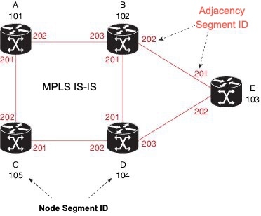
    The following diagram shows a basic network with the Node SID and the Adjacency SID for each of the devices and connections between the devices noted.

Segment Routing Policies

An SR policy path is expressed as a list of segments that specifies the path (SID list). By combining prefix (node) and adjacency segment IDs in an ordered list, any path within a network can be constructed. At each hop, the top segment is used to identify the next hop. Segments are stacked in order at the top of the packet header. When the top segment contains the identity of another node, the receiving node uses equal cost multipaths (ECMP) to move the packet to the next hop. When the identity is that of the receiving node, the node pops the top segment and performs the task that is required by the next segment.

There are two types of SR policies: dynamic and explicit.

Dynamic SR Policy

A dynamic path is based on an optimization objective and a set of constraints. The headend computes a solution, resulting in a SID list or a set of SID lists. When the topology changes, a new path is computed. If the headend does not have enough information about the topology, the headend might delegate the computation to a path computation engine (PCE). If a path isn't found, then the policy becomes operationally down (operation status down) and packets will not be routed based on the policy.

Explicit SR Policy

When you configure an explicit policy, you specify an explicit path which consists of a list of prefix or adjacency SIDs, each representing a node or link along on the path. Each segment is an end-to-end path from the source to the destination, and instructs the routers in the network to follow the specified path instead of the shortest path calculated by the IGP. If a packet is steered into an SR policy, the SID list is pushed on the packet by the headend. The rest of the network executes the instructions embedded in the SID list.


Note

For PCC-initiated policies, if the explicit path is configured in the form of IP addresses, the policy goes operational status down if one of the hops goes down. If it is configured as a list of labels, then the policy goes operational status down only if it is the first hop that goes down. The remaining hops are not resolved by the PCC and so it will not take the policy operational status down if they fail.


Segment Routing over MPLS (SR-MPLS)

Segment Routing can be applied on an MPLS data plane. In an SR-MPLS enabled network, an MPLS label represents an instruction. The source nodes programs the path to a destination in the packet header as a stack of labels. For more information, see IETF RFC 8660 Segment Routing with the MPLS Data Plane.

Segment Routing over IPv6 (SRv6)

Segment Routing over IPv6 (SRv6) extends Segment Routing support with an IPv6 data plane. SRv6 introduces the Network Programming framework that enables a network operator or an application to specify a packet processing program by encoding a sequence of instructions in the IPv6 packet header. Each instruction is implemented on one or several nodes in the network and identified by an SRv6 Segment Identifier (SID) in the packet. For more information, see IETF RFC 8986 SRv6 Network Programming.

In SRv6, an IPv6 address represents an instruction. SRv6 uses a new type of IPv6 Routing Extension Header, called the Segment Routing Header (SRH), in order to encode an ordered list of instructions. The active segment is indicated by the destination address of the packet, and the next segment is indicated by a pointer in the SRH.

For more information, see https://www.segment-routing.net/.

SRv6 Limitations

  • Cisco IOS XR 7.3.2 only supports SRv6 visualization with IS-IS IGP.

  • Traffic collection on SRv6 policies is not currently supported.

  • OSPFv3 IGP (PCE-initiated) SRv6 policies are not supported.

  • SRv6 is not supported on Bandwidth Optimization, Bandwidth on Demand, or Local Congestion Mitigation feature packs.

  • IPv4 and IPv6 topologies must be congruent. Different link metrics for IPv4 and IPv6 are not supported.

  • Visualization of PCC-initiated dynamic path SRv6 policies only. PCE-initiated and explicit path are not supported.

Segment Routing for Traffic Engineering

SR-TE takes place through a policy between a source and destination pair. SR-TE uses the concept of source routing, where the source calculates the path and encodes it in the packet header as a segment.

SR-TE utilizes network bandwidth more effectively than traditional MPLS-TE networks by using ECMP at every segment level. It uses a single intelligent source and relieves remaining routers from the task of calculating the required path through the network.

Disjointness

Crosswork can use a disjoint policy to compute two unique paths that steer traffic from the same source and destination avoiding common specified resources (links or nodes). This results in no single point of failure in steering traffic through the network. The following disjoint path computations are supported:

  • Link – Specifies that links are not shared on the computed paths.

  • Node – Specifies that nodes are not shared on the computed paths.

  • SRLG – Specifies that links with the same Share Risk Link Group (SRLG) value are not shared on the computed paths.

  • SRLG-node – Specifies that SRLG and nodes are not shared on the computed paths.


Note

  • Disjointness is supported for two policies with the same disjoint ID.

  • Configuration of affinity and disjointness at the same time is not supported.


Tree-SID Policies

Tree Segment Identifier (Tree-SID) is modern controller driven multicast technology based on Segment Routing. It is a tree-building solution that uses a Segment Routing Path Computation Element (SR-PCE) using path computation element protocol (PCEP) to calculate point-to-multipoint (P2MP) trees using SR policies. Tree-SID uses a single MPLS label to build a multicast replication tree in an SR network. The advantage of having a controller is that any sort of constraints can be applied to calculate the tree.

See View a Point-to-Multipoint Tree on the Topology Map

Flexible Algorithms

Flexible Algorithm allows operators to customize and compute the IGP shortest path according to their own needs and constraints (specific metrics and link properties). Many possible constraints can be used to compute a path over a network. For example, Flexible Algorithm can confine the path to a particular plane for networks with multiple logical planes. Since the meaning of the algorithm is not defined by any standard, but is defined by the user, it is called a Flexible Algorithm.

See Visualize Flexible Algorithm

About Resource Reservation Protocol (RSVP)

Resource Reservation Protocol (RSVP) is a signaling protocol that enables systems to request resource reservations from the network. RSVP processes protocol messages from other systems, processes resource requests from local clients, and generates protocol messages. As a result, resources are reserved for data flows on behalf of local and remote clients. RSVP creates, maintains, and deletes these resource reservations.

The RSVP-TE process contains the following functionalities:

  • Endpoint control, which is associated with establishing and managing TE tunnels at the headend and tail end.

  • Link-management, which manages link resources to do resource-aware routing of TE LSPs and to program MPLS labels.

  • Fast Reroute (FRR), which manages the LSPs that need protection and to assign backup tunnel information to these LSPs.

The interactions between TE and RSVP assume the existence of the endpoint control, link-management, and FRR functionality within TE.

RSVP-TE Explicit Routing (Strict, Loose)

RSVP-TE explicit routes are particular paths in the network topology that you can specify as abstract nodes, which could be a sequence of IP prefixes or a sequence of autonomous systems, in the Explicit Route Object (ERO). The explicit path can be administratively specified, or automatically computed using an algorithm such as constrained shortest path first (CSPF).

The explicit path that is specified in the ERO could be a strict path or a loose path.

A strict path means that a network node and its preceding node in the ERO must be adjacent and directly connected.

A loose hop means that a network node specified in the ERO must be in the path but is not required to be directly connected to its preceding node. If a loose hop is encountered during ERO processing, the node that processes the loose hop can update the ERO with one or more nodes along the path from itself to the next node in the ERO. The advantage of a loose path is that the entire path does not need to be specified or known when creating the ERO. The disadvantage of a loose path is that it can result in forwarding loops during transients in the underlying routing protocol.


Note

RSVP-TE tunnels cannot be configured with loose hops when provisioning within the UI.


RSVP FRR

When a router’s link or neighboring device fails, the router often detects this failure by receiving an interface-down notification. When a router notices that an interface has gone down, it switches LSPs going out that interface onto their respective backup tunnels (if any).

The FRR object is used in the PATH message and contains a flag that identifies the backup method to be used as facility-backup. The FRR object specifies setup and hold priorities, which are included in a set of attribute filters and bandwidth requirements to be used in the selection of the backup path.

The Record Route Object (RRO) reports in the RESV message the availability or use of local protection on an LSP, and whether bandwidth and node protection are available for that LSP.

The signaling of the FRR requirements is initiated at the TE tunnel headend. Points of Local Repair (PLR) along the path act on the FRR requirements based on the backup tunnel availability at the PLR, and signal the backup tunnel selection information to the headend. When an FRR event is triggered, the PLR sends PATH messages through the backup tunnel to the merge point (MP) where the backup tunnel rejoins the original LSP. The MP also sends RESV messages to the PLR using the RSVP-Hop object that is included by the PLR in its PATH message. This process prevents the original LSP from being torn down by the MP. Also, the PLR signals the tunnel headend with a PATH-ERROR message to indicate the failure along the LSP and that FRR is in active use for that LSP. This information is used by the headend to signal a new LSP for the TE tunnel, and to tear down the existing failed path after the new LSP is set up through make-before-break techniques.