- Preface
- Cisco APIC-EM Appliance Networks
- Cisco APIC-EM Series Appliances
- Installing and Configuring a Cisco APIC-EM Appliance
- Installing Cisco APIC-EM on a VMware Virtual Machine
- Managing Administrator Accounts
- Performing Post-Installation Tasks
- Installing the Cisco APIC-EM Series Appliance in a Rack
- Cisco APIC-EM Appliance Specifications
- Cisco APIC-EM Appliance Port Reference
- Cisco APIC-EM Licenses
- Index
Installing the Cisco
APIC-EM Series Appliance in a Rack
This appendix describes how to install the Cisco APIC-EM appliance in a rack.
 Note | Before you install, operate, or service a Cisco APIC-EM series appliance, review the Regulatory Compliance and Safety Information for Cisco UCS C-Series Servers for important safety information. |
IMPORTANT SAFETY INSTRUCTIONS
 Warning | This warning symbol means danger. You are in a situation that could cause bodily injury. Before you work on any equipment, be aware of the hazards involved with electrical circuitry and be familiar with standard practices for preventing accidents. Use the statement number provided at the end of each warning to locate its translation in the translated safety warnings that accompanied this device. Statement 1071 |
SAVE THESE INSTRUCTIONS
- Unpacking and Inspecting the Appliance
- Preparing for Appliance Installation
- Equipment Requirements
- Connecting and Powering On the Appliance
- Checking the LEDs
- Installing or Replacing Appliance Components
Unpacking and Inspecting the Appliance
 Caution | When handling internal appliance components, wear an ESD strap and handle modules by the carrier edges only. |
 Tip | Keep the shipping container in case the appliance requires shipping in the future. |
Note | The chassis is thoroughly inspected before shipment. If any damage occurred during transportation or any items are missing, contact your customer service representative immediately. |
What to Do Next
Prepare for the appliance installation.
Preparing for Appliance Installation
This section provides information about preparing for the Cisco APIC-EM series appliance installation.
Installation Guidelines
Warning | To prevent the system from overheating, do not operate it in an area that exceeds the maximum recommended ambient temperature of: 40° C (104° F). Statement 1047 |
Warning | The plug-socket combination must be accessible at all times, because it serves as the main disconnecting device. Statement 1019 |
Warning | This product relies on the building’s installation for short-circuit (overcurrent) protection. Ensure that the protective device is rated not greater than: 250 V, 15 A. Statement 1005 |
Warning | Installation of the equipment must comply with local and national electrical codes. Statement 1074 |
Caution | To ensure proper airflow it is necessary to rack the appliances using rail kits. Physically placing the units on top of one another or “stacking” without the use of the rail kits blocks the air vents on top of the appliances, which could result in overheating, higher fan speeds, and higher power consumption. We recommend that you mount your appliances on rail kits when you are installing them into the rack because these rails provide the minimal spacing required between the appliances. No additional spacing between the appliances is required when you mount the units using rail kits. |
Caution | Avoid UPS types that use ferroresonant technology. These UPS types can become unstable with systems such as the Cisco UCS, which can have substantial current draw fluctuations from fluctuating data traffic patterns. |
When you are installing an appliance, use the following guidelines:
-
Plan your site configuration and prepare the site before installing the appliance. For reference, see the Cisco UCS Site Preparation Guide for the recommended site planning tasks.
-
Ensure that there is adequate space around the appliance to allow for servicing the appliance and for adequate airflow. The airflow in this appliance is from front to back.
-
Ensure that the air-conditioning meets the thermal requirements listed in the Appliance Specifications.
-
Ensure that the cabinet or rack meets the requirements listed in the following "Rack Requirements" section.
-
Ensure that the site power meets the power requirements listed in the Appliance Specifications. If available, you can use an uninterruptible power supply (UPS) to protect against power failures.
Rack Requirements
This section provides the requirements for the standard open racks.
The rack must be of the following type:
-
A standard 19-in. (48.3-cm) wide, four-post EIA rack, with mounting posts that conform to English universal hole spacing, per section 1 of ANSI/EIA-310-D-1992.
-
The rack post holes can be square 0.38-inch (9.6 mm), round 0.28-inch (7.1 mm), #12-24 UNC, or #10-32 UNC when you use the supplied slide rails.
-
The minimum vertical rack space per server must be one RU, equal to 1.75 in. (44.45 mm).
Equipment Requirements
The slide rails sold by Cisco Systems for this appliance do not require tools for installation.
- Supported Slide Rail Kits
- Slide Rail Adjustment Range and Cable Management Arm Dimensions
- Installing the Appliance In a Rack
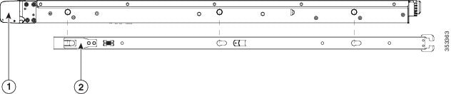
Supported Slide Rail Kits
This appliance supports two rail kit options:
Do not attempt to use a rail kit that was for the Cisco UCS C220 M3 server; the rail kits for the Cisco APIC-EM appliance have been designed specifically for it.
Slide Rail Adjustment Range and Cable Management Arm Dimensions
The slide rails for this server have an adjustment range of 24 to 36 inches (610 to 914 mm).
The optional cable management arm (CMA) adds additional length requirements:
Installing the Appliance In a Rack
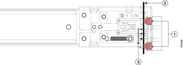
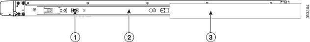
Installing the Slide Rails
This section describes how to install the appliance in a rack using the rack kits that are sold by Cisco.
Warning | To prevent bodily injury when mounting or servicing this unit in a rack, you must take special precautions to ensure that the system remains stable. The following guidelines are provided to ensure your safety: This unit should be mounted at the bottom of the rack if it is the only unit in the rack. When mounting this unit in a partially filled rack, load the rack from the bottom to the top with the heaviest component at the bottom of the rack. If the rack is provided with stabilizing devices, install the stabilizers before mounting or servicing the unit in the rack. Statement 1006 |
What to Do Next
If necessary for your installation, install the cable management arm.
Installing the Cable Management Arm (Optional)
The following procedure describes how to install the cable management arm.
The CMA is reversible left to right. To reverse the CMA, see Reversing the Cable Management Arm (Optional) section, before installation.
| Step 1 | With the server pushed fully into the rack, slide the CMA tab of the CMA arm that is farthest from the server onto the end of the stationary slide rail that is attached to the rack post (see the figure below). Slide the tab over the end of the rail until it clicks and locks. | ||||||||
| Step 2 | Slide the CMA tab that is closest to the server over the end of the inner rail that is attached to the server (see the figure below). Slide the tab over the end of the rail until it clicks and locks. | ||||||||
| Step 3 | Pull out the width-adjustment slider that is at the opposite end of the CMA assembly until it matches the width of your rack (see the figure below). | ||||||||
| Step 4 | Slide the CMA tab that is at the end of the width-adjustment slider onto the end of the stationary slide rail that is attached to the rack post (see figure below). Slide the tab over the end of the rail until it clicks and locks. | ||||||||
| Step 5 | Open the hinged
flap at the top of each plastic cable guide and route your cables through the
cable guides as desired.
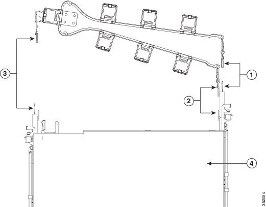 The following table describes the components of the CMA.
|
Reversing the Cable Management Arm (Optional)
The following procedure describes how to reverse the cable management arm.
| Step 1 | Rotate the entire CMA assembly 180 degrees. The plastic cable guides must remain pointing upward. | ||||
| Step 2 | Flip the tabs at the end of each CMA arm so that they point toward the rear of the server. | ||||
| Step 3 | Pivot the tab
that is at the end of the width-adjustment slider. Depress and hold the metal
button on the outside of the tab and pivot the tab 180 degrees so that it
points toward the rear of the server.
 Refer to the following figure when reversing the cable management arm.
|
Connecting and Powering On the Appliance
This section describes how to power on the appliance and assign an IP address to connect to it.
| Step 1 | Attach a
supplied power cord to each power supply in the appliance and then attach the
power cord to a grounded AC power outlet. See the
Power Specifications, for power specifications.
Wait for approximately two minutes to let the appliance boot in standby power during the first bootup. You can verify the power status by looking at the Power Status LED:
| ||
| Step 2 | Connect a USB
keyboard and VGA monitor by using the supplied KVM cable connected to the KVM
connector on the front panel.
| ||
| Step 3 | Refer to the following sections for configuring and using CIMC to assign an IP address to the appliance: |
Checking the LEDs
When the Cisco APIC-EM series appliances have been started up and are running, observe the state of the front-panel and rear-panel LEDs. The following topics describe the LED color, its power status, activity, and other important status indicators that are displayed for the Cisco-APIC-EM series appliance.
Front Panel LEDs and Buttons
The following table describes the appliance front panel LEDs and buttons on the appliance.
Note | The minimum network interface speed for the appliance should be 1 GB a second. |
|
LED Name |
State |
|---|---|
|
Front Panel LEDs and Buttons |
Off—There is no AC power to the appliance. Amber—The appliance is in standby power mode. Power is supplied only to the CIMC and some motherboard functions. Green—The appliance is in main power mode. Power is supplied to all server components. |
|
Identification |
Off—The Identification LED is not in use. Blue—The Identification LED is activated. |
|
System status |
Green—The appliance is running in a normal operating condition. Green, blinking—The appliance is performing system initialization and memory checks. Amber, steady—The appliance is in a degraded operational state, which may be due to one of the following: – Power supply redundancy is lost. – CPUs are mismatched. – At least one CPU is faulty. – At least one DIMM is faulty. – At least one drive in a RAID configuration failed. Amber, blinking—The appliance is in a critical fault state, which may be due to one of the following: – Boot failed. – Fatal CPU and/or bus error is detected. – Server is in an over-temperature condition. |
|
Fan status |
Green—All fan modules are operating properly. Amber, steady—One fan module has failed. Amber, blinking—Critical fault, two or more fan modules have failed. |
|
Temperature status |
Green—The appliance is operating at normal temperature. Amber, steady—One or more temperature sensors have exceeded a warning threshold. Amber, blinking—One or more temperature sensors have exceeded a critical threshold |
|
Power supply status |
Green—All power supplies are operating normally. Amber, steady—One or more power supplies are in a degraded operational state. Amber, blinking—One or more power supplies are in a critical fault state. |
|
Network link activity |
Off—The Ethernet link is idle. Green—One or more Ethernet LOM ports are link-active, but there is no activity. Green, blinking—One or more Ethernet LOM ports are link-active, with activity. |
|
Hard drive fault |
Off—The hard drive is operating properly. Amber—The hard drive has failed. Amber, blinking—The device is rebuilding. |
|
Hard drive activity |
Off—There is no hard drive in the hard drive sled (no access, no fault). Green—The hard drive is ready. Green, blinking—The hard drive is reading or writing data. |
Rear Panel LEDs and Buttons
The following table describes the appliance rear panel LEDs and buttons on the appliance.
Note | The minimum network interface speed for the appliance should be 1 GB a second. |
|
LED Name |
State |
|---|---|
|
Power supply fault |
Off—The power supply is operating normally. Amber, blinking—An event warning threshold has been reached, but the power supply continues to operate. Amber, solid—A critical fault threshold has been reached, causing the power supply to shut down (for example, a fan failure or an over-temperature condition). |
|
Power supply AC OK |
Off—There is no AC power to the power supply. Green, blinking—AC power OK, DC output not enabled. Green, solid—AC power OK, DC outputs OK. |
|
1 Gb Ethernet dedicated management link speed |
Off—link speed is 10 Mbps. Amber—link speed is 100 Mbps. Green—link speed is 1 Gbps. |
|
1 Gb Ethernet dedicated management link status |
Off—No link is present. Green—Link is active. • Green, blinking—Traffic is present on the active link. |
|
1 Gb Ethernet link speed |
Off—link speed is 10 Mbps. Amber—link speed is 100 Mbps. Green—link speed is 1 Gbps. |
|
1 Gb Ethernet link status |
Off—No link is present. Green—Link is active. Green, blinking—Traffic is present on the active link. |
|
Identification |
Off—The Identification LED is not in use. Blue—The Identification LED is activated. |
Installing or Replacing Appliance Components
Refer to the Cisco UCS C220 Server Installation and Service Guide for information on how to install or replace the Cisco APIC-EM appliance components.
 Feedback