Using the Topology Map
- About Topology
- Displaying Device Data
- Aggregating Devices
- Configuring the Topology Structure
- Saving a Topology Layout
- Opening a Saved Topology Layout
- Changing a Device's Role From the Topology Window
- Searching for Devices
- Applying Tags to Devices
- Displaying Devices with Tags
About Topology
The Topology window displays a graphical view of your network. Using the discovery settings that you have configured, the Cisco APIC-EM discovers and maps devices to a physical topology with detailed device-level data.
To access the Topology window, click Topology in the Navigation pane. The Topology window appears.
The topology map includes the following key features:
-
Auto-visualization of Layer 2 and 3 topologies on top of the physical topology provides a granular view for design planning and simplified troubleshooting.
-
For a Layer 2 topology, the controller discovers configured VLANs within your network to display in the Topology window. For a Layer 3 topology, the controller discovers all forms of a Layer 3 topology (OSPF, IS-IS, etc.), depending on what is currently configured and in use within your network to display in the Topology window.
-
You can click on a device icon to display information about that device.
-
You can perform a path trace and then view the trace in the topology map. For additional information about the performing a path trace, see About Path Trace.
 Note | Individual device configurations are retrieved and stored in a network information base (NIB). |
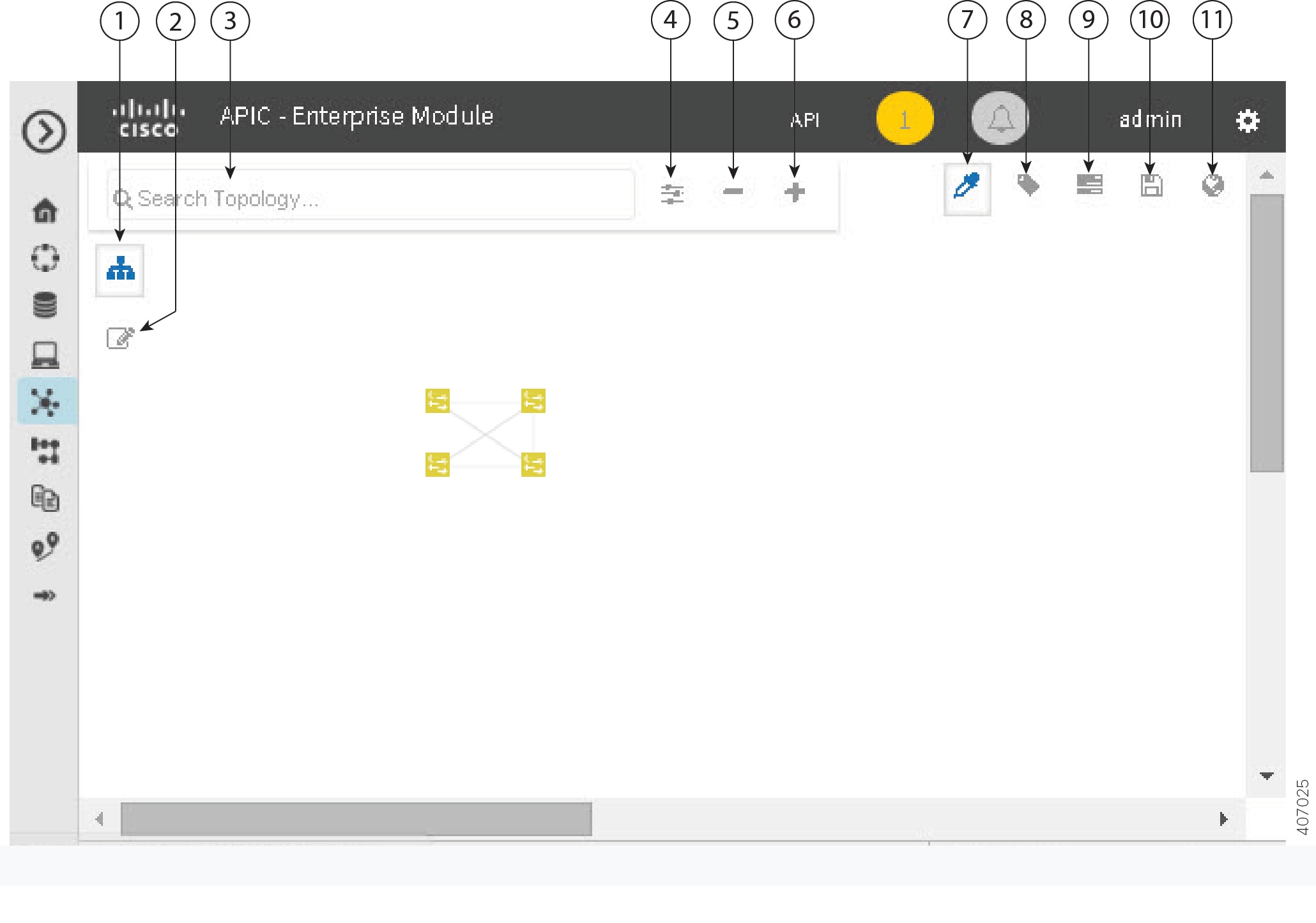
Topology Toolbar
The Topology toolbar is located at the top of the Topology window.
|
Callout Number |
Icon Name |
Description |
||||
|---|---|---|---|---|---|---|
|
1 |
Toggle Aggregation |
Enables or disables device aggregation. Aggregating devices means grouping devices together. You can group devices in any way that makes sense to you. You can save the layout for future reference by clicking the Save icon. This grouping does not effect the physical configuration on the devices. Aggregation is enabled by default. |
||||
|
2 |
Toggle Multiselect |
Allows you to select multiple devices by dragging the mouse over the desired devices or shift-clicking on devices. You can also select multiple groups of devices by clicking shift and dragging the mouse over a group of devices. After selecting the group of devices, you can aggregate or tag them. If you aggregate devices of different product families, the Cisco APIC-EM shows them as generic devices (without a device type) and the number of devices. Multiselect is off by default. |
||||
|
3 |
Search Topology |
Searches for a host or device by host name, device name, device type, or IP address. As you enter information into this field, the Cisco APIC-EM displays matches. Select the host or device from the results that appear. The selected host or device appears in the Topology window. |
||||
|
4 |
Filters |
Allows you to choose a filter that you can apply to the topology map. For each filter, you can make additional adjustments using the Advanced options. For information, see Configuring the Topology Structure.
|
||||
|
5 |
Zoom out |
|
||||
|
6 |
Zoom in |
Adjusts the Topology window's view. Click the + (plus) icon on the menu bar to maximize the view of the network hosts and devices. |
||||
|
7 |
Toggle Color Code |
Toggles between displaying the device icons in different colors or in a single color. Color coding is enabled by default. |
||||
|
8 |
Tags |
Displays the available tags. Clicking on an individual tag highlights the device or devices in the Topology window that have this tag. You can also apply tags to devices by selecting the device, clicking Device Tagging in the Device Information dialog box, and then creating and applying the tags. |
||||
|
9 |
Layers |
Displays devices with the following attributes on the topology map:
|
||||
|
10 |
Save and Load Options |
Displays the following options: |
||||
|
11 |
Map view |
Displays the Topology map view. Click this icon to view the network topology in a graphical representation of your network's physical location.
|
Topology Icons
The following icons appear in the Topology window:
|
Icon |
Network Element |
Description |
||
|---|---|---|---|---|
|
|
Cloud |
Representation of the external network. |
||
|
|
Router |
Displays the device name. |
||
|
|
Switch |
Displays the device name. |
||
|
|
Access Point |
Displays the device name. |
||
|
|
Wireless LAN Controller |
Displays the device name. |
||
|
|
Aggregated Devices |
Displays the number of aggregated devices and the device type.
|
||
|
|
Location Marker |
Displays the device name. The device icon is displayed with a location marker as a background. If you add location markers to your devices (from the Device Inventory window) and then click Topology in the navigation pane or click the Map button on the Topology toolbar, the Topology map view appears. The map view shows where you have placed your location markers (for example, San Jose and London). Click a location marker on the map to display the topology for that location (for example, San Jose). Devices that use a different location marker (for example, London) are shown with a location marker as a background. |
||
|
|
Links |
Lines between devices. Click on a link to display information about the connected devices.
|


Displaying Device Data
You can display data for a specific device in the Topology window. Displaying device data is helpful when troubleshooting network connectivity issues between devices.
Note | The device data that is accessible in the Topology window is also accessible in the Device Inventory window. |
The following device data is available:
-
Location (Location information is displayed if the selected device icon has a location marker background. Click the Location link to display the topology for devices that share that location marker.)
-
Type
-
Device role (For information about changing the device role, see Changing the Device Role.
-
IP address
-
MAC address
-
OS (operating system)
-
Software version
-
Ports -
VLAN (if exists)
-
Number of connections
-
List of connected devices (Each connected device shows its device type (icon) and the number of connections. Clicking on a connected device displays the details for that device.)
-
Tags
What to Do Next
Select and review data from other devices within your network, or perform other tasks including the following:
Aggregating Devices
You use the Cisco APIC-EM device aggregation feature to adjust how devices are displayed in the Topology window. This feature enhances network navigation and manageability.
- Aggregating Devices in the Topology Window
- Disaggregating Devices in the Topology Window
- Changing the Aggregated Devices Label
Aggregating Devices in the Topology Window
You can aggregate and disaggreate devices into and out of groups in the Topology window.
Scan your network using the discovery functionality of the Cisco APIC-EM to populate device inventory for the database.
Determine how the devices within your network configuration are to be visually grouped and organized.
| Step 1 | Click
Topology in the navigation pane.
The Topology window appears.
| ||
| Step 2 | Click the
Toggle Aggregation icon to enable device
aggregation.
| ||
| Step 3 | Drag and drop a device icon onto another device icon.
The device icon changes to an aggregated devices icon. For more information about the aggregated devices icon, see Topology Icons.
|
Disaggregating Devices in the Topology Window
Scan your network using the discovery functionality of the Cisco APIC-EM to populate device inventory for the database.
Determine how the devices within your network configuration are to be visually grouped and organized.
| Step 1 | From the
Navigation pane, click
Topology.
The Topology window appears.
| ||
| Step 2 | Click on an
aggregated devices icon.
A list of the aggregated devices appears. | ||
| Step 3 | From the list,
click the
Disaggregate link for each device that you want to
remove from the aggregated devices.
The device is removed from the list and from the aggregated devices icon. The aggregated device label and the aggregated devices icon are updated to reflect the number of devices. |
Changing the Aggregated Devices Label
The default label for aggregated devices is the number of devices and the device type (# devicetype Devices). However, you can change the default label to one that is meaningful in the context of your network topology.
Scan your network using the discovery functionality of the Cisco APIC-EM to populate device inventory for the database.
Determine how the devices within your network configuration are to be visually grouped and organized.
| Step 1 | From the
Navigation pane, click
Topology.
The Topology window appears.
| ||
| Step 2 | Click an
aggregated devices icon.
A list of the aggregated devices appears. At the top of the list is the aggregated devices label. | ||
| Step 3 | Click the aggregated devices label to open an edit field where you can change the label. | ||
| Step 4 | Change the label, then click outside of the edit field to save your changes. |
Configuring the Topology Structure
You can choose from three default topology layouts. You can also use advanced settings to modify these layouts, such as the overall size of the topology graph, the spacing that separates individual elements, and more.
Scan your network using the discovery functionality of the Cisco APIC-EM to populate device inventory for the database.
| Step 1 | From the
Navigation pane, click
Topology.
The Topology window appears.
| ||||||||||||||||||||||
| Step 2 | From the Topology toolbar, click the Filters icon. | ||||||||||||||||||||||
| Step 3 | Select a filter from the drop down list. Available options are Branch, Connections, or Device & Role. | ||||||||||||||||||||||
| Step 4 | Click the
Advanced View button to configure how each filter is
displayed. Click the
Basic
View button to return to the basic view.
|
What to Do Next
Save the current layout or load a previously saved layout. For information, see Saving a Topology Layout and Opening a Saved Topology Layout.
Saving a Topology Layout
You can save a topology layout so that you can open and view it later.
You must have administrator (ROLE_ADMIN) permissions to perform this procedure.
Make sure that you have devices in your inventory. If not, discover devices using the Discovery function.
| Step 1 | From the
Navigation pane, click
Topology.
The Topology window appears. |
| Step 2 | From the Topology toolbar, click the Save icon. |
| Step 3 | In the Topology Title field, enter a name for the topology and click Save as New. |
| Step 4 | Click
OK to confirm the save.
The topology is saved and the name appears at the top of the dialog box. |
Opening a Saved Topology Layout
You can open a topology layout that you have previously saved.
You must have administrator (ROLE_ADMIN) permissions to perform this procedure.
Make sure that you have devices in your inventory. If not, discover devices using the Discovery function.
| Step 1 | From the
Navigation pane, click
Topology.
The Topology window appears. |
| Step 2 | From the
Topology toolbar, click the
Save icon.
A dialog box appears listing the saved topology layouts. |
| Step 3 | For the topology layout that you want to open, click the Folder icon.. |
| Step 4 | Click
OK to confirm.
The topology layout opens in the Topology window. |
Changing a Device's Role From the Topology Window
During the scan process, a device role is automatically assigned to each discovered device. The device role is used for identifying and grouping devices according to their responsibilities and placement within the network.
A device can have one of the following roles within the Cisco APIC-EM:
-
Unknown—Device role is unknown.
-
Access—Device is located within and performs tasks required for the access layer or first tier/edge.
-
Border Router—Device performs the tasks required for a border router.
-
Distribution—Device is located within and performs tasks required for the distribution layer.
-
Core—Device is located within and performs tasks required for the core.
You can change the device role when you select a device and display the device data.
Note | You can also change the device role from the Device Inventory window. |
Scan your network using the discovery functionality of the Cisco APIC-EM to populate device inventory for the database.
| Step 1 | From the
Navigation pane, click
Topology.
The Topology window appears.
| ||
| Step 2 | Click a specific device in the Topology window to select it. | ||
| Step 3 | Choose a role from the Role drop-down list: Access, Core, Distribution, or Border Router. | ||
| Step 4 | (Optional) Select additional devices and change device roles. | ||
| Step 5 | Click the Filters icon on the Topology toolbar. | ||
| Step 6 | (Optional) Select a filter from the drop down list. Available options are Branch, Connections, or Device and Role. | ||
| Step 7 | Click the refresh button to the right of the filter type to update all of the device roles. The Topology structure refreshes showing the changed device roles. |
Searching for Devices
You use the Cisco APIC-EM search function to locate specific devices within your network. This function allows you to search the network using any string value. To locate a specific device quickly, use any of the following values in the search field:
Note | The search function supports fragmented results. For example, if you enter 12 in the search field, you will get results for devices with IP addresses or device names that contain 1 and 2 (.12, .120, .102, 10.20, 1-switch2, etc). |
Scan your network using the discovery functionality of the Cisco APIC-EM to populate device inventory for the database.
Determine the string value to be used within your network for your search.
| Step 1 | Click
Topology in the navigation pane.
The Topology window appears.
| ||
| Step 2 | From the
Topology toolbar, enter a keyword in the
Search
Topology field.
As you begin typing, the controller displays a list of possible matches to your entry.
| ||
| Step 3 | Click on a device from the search results to highlight that device and its links in the Topology window. Click on the device again to display detailed data for that device. | ||
| Step 4 | Proceed with any provisioning or troubleshooting tasks on the located devices. |
What to Do Next
Search using other string values for other devices within your network, or perform other tasks including the following:
Applying Tags to Devices
You use the Cisco APIC-EM tag feature to associate devices within your network with a single attribute. A tag also enables the grouping of devices based upon an attribute. For example, you can create a tag and use it to group devices based upon a platform ID, Cisco IOS releases, or location.
To apply tags to devices within your network in the Topology window, perform the following steps.
Note | Applying a tag to a host is not supported. |
You should have performed the following tasks:
| Step 1 | From the
Navigation pane, click
Topology.
The Topology window appears. | ||
| Step 2 | Click the device
or devices you want to tag. To select more than one device, click the
Multiselect icon. For information about how to use
the multiselect function, see
Topology Icons.
| ||
| Step 3 | Click
Device
Tagging.
The Device Tagging dialog box appears. | ||
| Step 4 | From the Available Tags column, click a tag to apply it to the selected device or devices. If the tag you want does not exist, you can create it by following these steps: | ||
| Step 5 | When you are done tagging, click x to close the dialog box. | ||
| Step 6 | You can verify the tagging by clicking on one of the devices that you tagged. The Device Information dialog box shows the Tags field with the total number and the names of the tags applied to the device. |
Displaying Devices with Tags
To display tagged devices from the Topology window, perform the following steps.
Discover the devices in your network.
Create tags and apply them either through the Device Inventory or Topology window.
| Step 1 | From the Navigation pane, click
Topology.
The Topology window appears. | ||
| Step 2 | From the Topology toolbar, click the
Tags.
A tag selection box appears. | ||
| Step 3 | To identify the devices associated with a tag, click the tag. To
return the devices to their normal display, click the tag again.
Tags are color-coded, so when you click a tag, a circle of the same color is drawn around its associated devices.
|
 Feedback