- About this Guide
- General Overview
- Command Line Interface
- Operations
- Utilities
- Configuring the Management Interface and Security
- Configuring the Line Interface
- Configuring the Connection
- Raw Data Formatting: The RDR Formatter and NetFlow Exporting
- Managing Subscribers
- Redundancy and Fail-Over
- Identifying and Preventing Distributed-Denial-Of-Service Attacks
- Value Added Services (VAS) Traffic Forwarding
- MPLS/VPN Support
- Managing the SCMP
- Monitoring SCE Platform Utilization
- Proprietary MIB Reference
- How to Configure the Line Interfaces
- How to Configure Tunneling Protocols
- How to Select the Tunneling Mode
- How to Display the Tunneling Configuration
- How to Display the Logged-in VPNs
Configuring the Line Interface
This module describes how to configure the physical line interfaces (ports) as well how to configure those interfaces for tunneling, VLAN translation, TOS marking, and traffic rules.
•![]() How to Configure the Line Interfaces
How to Configure the Line Interfaces
•![]() How to Configure Tunneling Protocols
How to Configure Tunneling Protocols
•![]() How to Configure VLAN Translation
How to Configure VLAN Translation
•![]() How to Configure Traffic Rules and Counters
How to Configure Traffic Rules and Counters
How to Configure the Line Interfaces
•![]() How to Configure the Gigabit Ethernet Line Interfaces
How to Configure the Gigabit Ethernet Line Interfaces
•![]() How to Configure the Fast Ethernet Line Interfaces
How to Configure the Fast Ethernet Line Interfaces
Line Interfaces
The Line Interfaces (Subscriber and Network) are used to connect the SCE platform to the network. See the description of network topologies in the Topology section of the Cisco SCE 2000/SCE 1000 Installation and Configuration Guides .
The SCE 1000 2xGBE and the SCE 2000 4xGBE have Gigabit Ethernet line interfaces. You should configure auto-negotiate for these interfaces.
The SCE 2000 4/8x FE has Fast Ethernet line interfaces. You should configure the speed and duplex for these interfaces.
How to Configure the Gigabit Ethernet Line Interfaces

Note ![]() The maximum packet size supported by the SCE platform is 1600 bytes
The maximum packet size supported by the SCE platform is 1600 bytes
Step 1 ![]() At the SCE# prompt, type
At the SCE# prompt, type configure , and press Enter.
Enters Global Configuration mode.
Step 2 ![]() At the SCE(config)# prompt, type
At the SCE(config)# prompt, type interface GigabitEthernet 0/ portnumber, and press Enter, where portnumber is the number of the selected port (1-4).
Enters Interface Configuration mode for the selected GBE interface.
Step 3 ![]() At the SCE(config if)# prompt, type
At the SCE(config if)# prompt, type auto-negotiate, and press Enter.
Enables auto-negotiation.
Step 4 ![]() At the SCE(config if)# prompt, type
At the SCE(config if)# prompt, type exit and press Enter.
Exits to global configuration mode, from which you can access a different Gigabit Ethernet interface.
Step 5 ![]() Repeat steps 2 and 3 for the remaining Gigabit Ethernet interfaces.
Repeat steps 2 and 3 for the remaining Gigabit Ethernet interfaces.
Auto-negotiation must enabled separately and explicitly for each Gigabit Ethernet interface.
How to Configure the Fast Ethernet Line Interfaces
Note that both sides of the FE link (both the SCE 2000 4/8xFE and the remote device) should have the same configuration. Use either of the following two configuration options:
•![]() Autonegotiation = ON
Autonegotiation = ON
•![]() Autonegotiation = ON, speed = 100
Autonegotiation = ON, speed = 100
Step 1 ![]() At the SCE# prompt, type
At the SCE# prompt, type configure , and press Enter.
Enters Global Configuration mode.
Step 2 ![]() At the SCE(config)# prompt, type
At the SCE(config)# prompt, type interface FastEthernet 0/ portnumber, and press Enter, where portnumberis the number of the selected port (1-4).
Enters Interface Configuration mode for the selected FE interface.
Step 3 ![]() At the SCE(config if)# prompt, type
At the SCE(config if)# prompt, type duplex auto|full|half, and press Enter.
Configures the duplex mode for the selected FE interface.
Step 4 ![]() At the SCE(config if)# prompt, type
At the SCE(config if)# prompt, type speed auto|100, and press Enter.
Configures the speed for the selected FE interface.
Step 5 ![]() At the SCE(config if)# prompt, type
At the SCE(config if)# prompt, type exit and press Enter.
Exits to global configuration mode, from which you can access a different Fast Ethernet interface.
Step 6 ![]() Repeat steps 2 through 5 for the remaining Fast Ethernet interfaces.
Repeat steps 2 through 5 for the remaining Fast Ethernet interfaces.
Speed and duplex mode must enabled separately and explicitly for each Fast Ethernet interface.
How to Configure Tunneling Protocols
•![]() How to Select the Tunneling Mode
How to Select the Tunneling Mode
•![]() How to Display the Tunneling Configuration
How to Display the Tunneling Configuration
•![]() How to Display the Logged-in VPNs
How to Display the Logged-in VPNs
•![]() VPNs
VPNs
About Tunneling Protocols
Tunneling technology is used across various telecommunications segments to solve a wide variety of networking problems. The SCE platform is designed to recognize and process various tunneling protocols in several ways. The SCE platform is able to either ignore the tunneling protocols ("skip" the header) or treat the tunneling information as subscriber information ("classify"). A special case of classification by tunneling information is MPLS/VPN with private IP support
The following table shows the support for the various tunneling protocols (the default behavior for each protocol is in bold):
When the tunneling information is ignored, the subscriber identification is the subscriber IP of the IP packet carried inside the tunnel.
L2TP
L2TP is an IP-based tunneling protocol, therefore the system must be specifically configured to recognize the L2TP flows, given the UDP port used for L2TP. The SCE platform can then skip the external IP, UDP, and L2TP headers, reaching the internal IP, which is the actual subscriber traffic. If L2TP is not configured, the system treats the external IP header as the subscriber traffic, thus all the flows in the tunnel are seen as a single flow .
VLAN
A single VLAN tag is supported per packet (no QinQ support).
Subscriber classification by VLAN tag is supported only in symmetric VLAN environments - i.e. where the upstream and downstream tags of a flow are identical.
MPLS
MPLS/VPN-based subscribers with private IP support are a special case of classification by tunneling information.
MPLS labels are supported up to a maximum of 15 labels per packet.
For more information regarding MPLS/VPN-based subscribers, see the MPLS/VPN Support, page 13-1
VPNs
A VPN is a named entity, introduced in the same way that a subscriber is introduced, and containing VPN mappings.
A VPN may contain several MPLS mappings or a single VLAN mapping. A VPN-based subscriber contains a set of mappings of the form: IP@VpnName, where IP can be either a single IP address or a range of addresses.
VPN entities can be configured only via the SM. The SCE platform CLI can be used to view VPN-related information, but not to configure the VPNs.
Private IP Addresses
Private IP addresses are supported only in the following modes, as these modes provide information regarding the higher-level entity (VLAN or VPN) to which the IP addresses of the flow belong:
•![]() MPLS VPN auto-learn
MPLS VPN auto-learn
•![]() VLAN symmetric classify
VLAN symmetric classify
Capacity
The system supports:
•![]() 2015 VPNs
2015 VPNs
•![]() 80,000 IP mappings over VPNs
80,000 IP mappings over VPNs
Limitations for VPN mode
Mutually exclusive system modes
When the system is working in VPN mode, the following modes are not supported:
•![]() TCP Bypass-establishment
TCP Bypass-establishment
•![]() DDoS
DDoS
•![]() Value Added Services (VAS) mode
Value Added Services (VAS) mode
Number of MPLS labels
•![]() The choice of the unique VPN site must be based on the BGP label only. The BGP label must be the innermost label.
The choice of the unique VPN site must be based on the BGP label only. The BGP label must be the innermost label.
•![]() The MPLS/VPN solution supports various combinations of labels.
The MPLS/VPN solution supports various combinations of labels.
•![]() The system does not support VPNs for which other MPLS-related features, such as MPLS-TE or MPLS-FRR, are enabled
The system does not support VPNs for which other MPLS-related features, such as MPLS-TE or MPLS-FRR, are enabled
Subscriber-related limitations
•![]() The SM must be configured to operate in Push mode.
The SM must be configured to operate in Push mode.
•![]() Introduced subscriber aging is not supported when using VPN-based subscribers
Introduced subscriber aging is not supported when using VPN-based subscribers
Topology-related limitations
•![]() An asymmetrical routing topology in which the traffic may be unidirectional, is not supported, since the identification of the VPN relies on the bidirectional nature of the traffic for various mechanisms.
An asymmetrical routing topology in which the traffic may be unidirectional, is not supported, since the identification of the VPN relies on the bidirectional nature of the traffic for various mechanisms.
TCP-related requirements
•![]() Number of Upstream TCP Flows - There must be enough TCP flows opening from the subscriber side on each PE-PE route in each period of time. The higher the rate of TCP flows from the subscriber side,the higher the accuracy of the mechanism can be.
Number of Upstream TCP Flows - There must be enough TCP flows opening from the subscriber side on each PE-PE route in each period of time. The higher the rate of TCP flows from the subscriber side,the higher the accuracy of the mechanism can be.
VPN configuration requirements
•![]() Two VPN sites must be aggregated into one VPN if the following conditions are both true:
Two VPN sites must be aggregated into one VPN if the following conditions are both true:
–![]() They are both connected to the same SCE platform †
They are both connected to the same SCE platform †
–![]() They both communicate with a common remote site using the same upstream labels and P router.
They both communicate with a common remote site using the same upstream labels and P router.
•![]() In MPLS-based VPNs (MPLS auto-learn mode), a subscriber MAY NOT have IP mappings over more than one VPN
In MPLS-based VPNs (MPLS auto-learn mode), a subscriber MAY NOT have IP mappings over more than one VPN
•![]() In VLAN-based VPNs (VLAN symmetric classify mode), a subscriber may have IP mappings over more than one VPN, but only if the IP mappings are the full range of the VPN (0.0.0.0/0). (This option is provided for backwards compatibility, supporting legacy multi-VLAN subscribers.)
In VLAN-based VPNs (VLAN symmetric classify mode), a subscriber may have IP mappings over more than one VPN, but only if the IP mappings are the full range of the VPN (0.0.0.0/0). (This option is provided for backwards compatibility, supporting legacy multi-VLAN subscribers.)
How to Select the Tunneling Mode
Use these commands to configure tunneling:
•![]() ip tunnel
ip tunnel
•![]() vlan
vlan
•![]() mpls
mpls
•![]() L2TP identify-by
L2TP identify-by
How to Configure IP Tunnels
By default, IP tunnel recognition is disabled. Use this command to configure recognition of L2TP tunnels and skipping into the internal IP packet.
The IP tunneling mode is mutually exclusive with VPN-based classification.
Step 1 ![]() From the SCE(config if)# prompt, type
From the SCE(config if)# prompt, type ip tunnel L2TP skip and press Enter.
Enables IP tunnel mode
•![]() To disable IP tunnels, use the following command:
To disable IP tunnels, use the following command:
no ip tunnel
How to Configure the VLAN Environment
Options
There are three options:
•![]() symmetric classify
symmetric classify
•![]() symmetric skip (default)
symmetric skip (default)
•![]() a-symmetric skip
a-symmetric skip
Symmetric environment refers to an environment in which the same VLAN tags are used for carrying a transaction in the upstream and downstream directions
Setting the mode to classify means that VPN and flow classification will use the VLAN tag. Using VLAN classification is mutually exclusive with other tunnel-based classification or IP tunnels.
An a-symmetric environment is an environment in which the VLAN tags might not be the same in the upstream and downstream directions of the same flow.
The SCE platform is configured by default to work in symmetric environments. A specific command should be used to allow correct operation of the SCE platform in asymmetric environments and instruct it to take into consideration that the upstream and downstream of each flow has potentially different VLAN tags.
Note ![]() Using the a-symmetric skip value incurs a performance penalty.
Using the a-symmetric skip value incurs a performance penalty.
Step 1 ![]() From the SCE(config if)# prompt, type
From the SCE(config if)# prompt, type vlan {symmetric classify | symmetric skip | a-symmetric skip} and press Enter.
Specify the desired VLAN mode.
Configuring the VLAN Environment: Example
The following example selects VLAN-based classification.
SCE(config if)#vlan symmetric classify
How to Configure the MPLS Environment
Use this command to set the MPLS environment.
•![]() Configuring the MPLS Environment: Example
Configuring the MPLS Environment: Example
Options
The following options are available:
•![]() traffic-engineering skip (default)—Use when all IP addresses are unique and MPLS labels are not mandatory for routing.
traffic-engineering skip (default)—Use when all IP addresses are unique and MPLS labels are not mandatory for routing.
•![]() VPN skip —Use when all IP addresses are unique, but MPLS labels are mandatory for routing.
VPN skip —Use when all IP addresses are unique, but MPLS labels are mandatory for routing.
•![]() VPN auto-learn —Use in an MPLS/VPN environment where auto-learning is required due to the existence of private IP addresses and/or VPN based subscribers.
VPN auto-learn —Use in an MPLS/VPN environment where auto-learning is required due to the existence of private IP addresses and/or VPN based subscribers.
When this option is configured, both ip-tunnel and VLAN must be set to their default values.
Use the VPN keyword when the labels are mandatory in the traffic, otherwise use traffic-engineering (default).
Note that using the VPN value incurs a performance penalty.
The MPLS VPN auto-learn option is required in an MPLS/VPN environment.
Step 1 ![]() From the SCE(config if)# prompt, type mpls {traffic-engineering skip|vpn skip|vpn auto-learn} and press Enter.
From the SCE(config if)# prompt, type mpls {traffic-engineering skip|vpn skip|vpn auto-learn} and press Enter.
Specify the desired MPLS mode.
Configuring the MPLS Environment: Example
The following example selects the MPLS/VPN tunnel environment.
SCE(config if)#mpls vpn auto-learn
About Changing VPN Modes
VPNs can only exist in either VLAN symmetric classify or MPLS VPN auto-learn, but these two modes cannot be enabled simultaneously. When changing from one of these VPN-related modes to another, keep the following guidelines in mind:
•![]() All VPN-based subscribers must be cleared to change the tunneling mode. If the connection with the SM is down, use the
All VPN-based subscribers must be cleared to change the tunneling mode. If the connection with the SM is down, use the no subscriber all with-vpn-mappings CLI command (see How to Remove VPN-based Subscribers, page 9-11 )
•![]() All VPN mappings must also be removed. This can only be done via the SM CLU (which means that the connection with the SM must be up). (See How to Manage VPN Mappings, page 13-26
All VPN mappings must also be removed. This can only be done via the SM CLU (which means that the connection with the SM must be up). (See How to Manage VPN Mappings, page 13-26
How to Restore the Default VLAN or MPLS Environment
Use this command to restore the default VLAN or MPLS configuration.
It is not usually necessary to explicitly restore the default environment, as this is done automatically when executing a VLAN or MPLS command. When such an automatic reset to default occurs, a warning message appears similar to the following:
Warning - Disabled previously configured IP-tunnel support or tunneling classification mode
Step 1 ![]() From the SCE(config if)# prompt, type
From the SCE(config if)# prompt, type default {mpls | vlan} and press Enter.
How to Configure the L2TP Environment
Use this command to set the port number that the LNS and LAC use for L2TP tunnels.
Options
The following option is available:
•![]() portnumber —The port number that the LNS and LAC use for L2TP tunnels.
portnumber —The port number that the LNS and LAC use for L2TP tunnels.
Default port# = 1701
Step 1 ![]() From the SCE(config if)# prompt, type
From the SCE(config if)# prompt, type L2TP identify-by port-number portnumberand press Enter.
Enables privileged EXEC mode.
Note ![]() If external fragmentation exists in the L2TP environment, it is required to configure a Traffic Rule (see How to Configure Traffic Rules and Counters ) that bypasses all IP traffic targeted to either the LNS or LAC IP address. This will make sure that any packets not having the L2TP port indication (i.e. non-first fragments) will not require handling by the traffic processors.
If external fragmentation exists in the L2TP environment, it is required to configure a Traffic Rule (see How to Configure Traffic Rules and Counters ) that bypasses all IP traffic targeted to either the LNS or LAC IP address. This will make sure that any packets not having the L2TP port indication (i.e. non-first fragments) will not require handling by the traffic processors.
How to Display the Tunneling Configuration
Step 1 ![]() From the SCE# prompt, type
From the SCE# prompt, type show interface linecard 0 MPLS|VLAN|L2TP|IP-tunnel and press Enter.
Displays the current configuration for the specified tunnel option.
How to Display the Logged-in VPNs
Options
The following options are available
•![]() vpn-name —The name of a specific currently logged-in VPN for which to display details.
vpn-name —The name of a specific currently logged-in VPN for which to display details.
•![]() all-names —Use this keyword to display all the VPN names that are currently logged into the system.
all-names —Use this keyword to display all the VPN names that are currently logged into the system.
Step 1 ![]() From the SCE>prompt, type
From the SCE>prompt, type show interface linecard 0 VPN {name vpn-name| all-names} and press Enter.
How to Configure VLAN Translation
•![]() VLAN Translation Features and Limitations
VLAN Translation Features and Limitations
•![]() How to Set the VLAN Translation Constant
How to Set the VLAN Translation Constant
•![]() How to Disable VLAN Translation
How to Disable VLAN Translation
•![]() How to Monitor VLAN Translation
How to Monitor VLAN Translation
About VLAN Translation
Some topologies require the SCE platform to be able to translate between different VLAN tags.
The following drawing illustrates an example of such a system, in which one router acts as a dispatcher, forwarding traffic and performing load balancing between two SCE 2000 platforms.
Figure 6-1 VLAN Translation
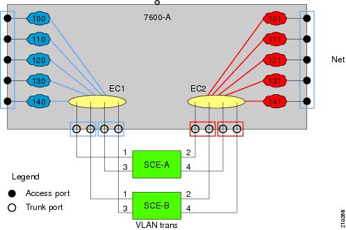
In this example, traffic enters the router via the access ports; it is forwarded to an EtherChannel, which is configured as a trunk, and enters the SCE 2000 platforms.
As can be seen from this drawing, the subscriber side VLAN tags must be different from those on the network side, or the router will simply forward the traffic to the opposite port. This can be supported very simply by having the SCE platform replace the VLAN tags according to a preset configuration.
VLAN Translation Features and Limitations
Features
•![]() Configuration of an increment or decrement constant.
Configuration of an increment or decrement constant.
•![]() Configuration of the constant is global for the line card.
Configuration of the constant is global for the line card.
•![]() The configured operation (either increment or decrement) is applied to the network side.
The configured operation (either increment or decrement) is applied to the network side.
•![]() The subscriber side automatically performs the opposite operation. That is, if the VLAN is incremented by X on the network side, it is decremented by X on the subscriber side.
The subscriber side automatically performs the opposite operation. That is, if the VLAN is incremented by X on the network side, it is decremented by X on the subscriber side.
•![]() VLAN tagged packets are changed (incremented or decremented) before transmission.
VLAN tagged packets are changed (incremented or decremented) before transmission.
•![]() Non-tagged packet are not changed.
Non-tagged packet are not changed.
•![]() This feature allows seamless processing with non-VLAN traffic.
This feature allows seamless processing with non-VLAN traffic.
Limitations
•![]() LIC Bypass not supported - Translation is done in the transmission. Therefore, in LIC bypass, where there is no transmission, there is also no translation.
LIC Bypass not supported - Translation is done in the transmission. Therefore, in LIC bypass, where there is no transmission, there is also no translation.
This means that in general, installations using the VLAN translation feature should rely on cutoff on failure and at upgrade (use redundant SCE platform).
•![]() STP hazard - VLAN translation may interfere with Spanning Tree Protocol. This should be taken in consideration when deploying the solution.
STP hazard - VLAN translation may interfere with Spanning Tree Protocol. This should be taken in consideration when deploying the solution.
•![]() The maximum offset that can be configured is 2047. Note that there is no protection for wraparound.
The maximum offset that can be configured is 2047. Note that there is no protection for wraparound.
How to Set the VLAN Translation Constant
Use this command to define the VLAN translation constant. Make sure that the same VLAN translation constant is configured for all SCE platforms in the system.
•![]() Setting the VLAN Translation Constant: Example
Setting the VLAN Translation Constant: Example
Options
The following options are available:
•![]() increment | decrement —Keywords indicating whether to increment or decrement the VLAN by the specified value.
increment | decrement —Keywords indicating whether to increment or decrement the VLAN by the specified value.
•![]() value — Integer value by which the VLAN is to incremented or decremented.
value — Integer value by which the VLAN is to incremented or decremented.
The configured translation is applied to the network port side. The reverse operation is performed at the subscriber side.
For example, if "increment 5" is defined, at the network port the VLAN is incremented by 5, and at the subscriber port the VLAN is decremented by 5.
In this case, the network side VLAN tags might be 105, 205, 305, and the subscriber side the VLAN tags would then be 100, 200, 300.
Default = 0
Maximum = 2047 (Note that there is no protection for wraparound of the VLAN value.)
Step 1 ![]() From the SCE(config if)# prompt, type
From the SCE(config if)# prompt, type vlan translation increment|decrement value valueand press Enter.
Sets the VLAN translation constant.
Setting the VLAN Translation Constant: Example
The following example sets the translation constant to 10, decremented at the network side.
SCE(config if)#vlan translation decrement value 10
How to Disable VLAN Translation
Step 1 ![]() From the SCE# prompt, type
From the SCE# prompt, type no vlan translation and press Enter
Disables VLAN translation.
How to Monitor VLAN Translation
Step 1 ![]() From the SCE# prompt, type show interface linecard 0 vlan translation and press Enter.
From the SCE# prompt, type show interface linecard 0 vlan translation and press Enter.
Displays current VLAN translation configuration.
How to Configure Traffic Rules and Counters
•![]() Information About Traffic Rules and Counters
Information About Traffic Rules and Counters
•![]() How to Configure Traffic Counters
How to Configure Traffic Counters
•![]() How to Configure Traffic Rules
How to Configure Traffic Rules
•![]() How to Manage Traffic Rules and Counters
How to Manage Traffic Rules and Counters
Information About Traffic Rules and Counters
•![]() What are Traffic Rules and Counters?
What are Traffic Rules and Counters?
What are Traffic Rules and Counters?
Traffic rules and counters may be configured by the user. This functionality enables the user to define specific operations on the traffic flowing through the SCE Platform, such as blocking or ignoring certain flows or counting certain packets. The configuration of traffic rules and counters is independent of the application loaded by the SCE platform, and thus is preserved when the application being run by the SCE platform is changed.
Possible uses for traffic rules and counters include:
•![]() Enabling the user to count packets according to various criteria. Since the traffic counters are readable via the SCE SNMP MIB, these might be used to monitor up to 32 types of packets, according to the requirements of the installation.
Enabling the user to count packets according to various criteria. Since the traffic counters are readable via the SCE SNMP MIB, these might be used to monitor up to 32 types of packets, according to the requirements of the installation.
•![]() Ignoring certain types of flows. When a traffic rules specifies an "ignore" action, packets matching the rule criteria will not open a new flow, but will pass through the SCE platform without being processed. This is useful when a particular type of traffic should be ignored by the SCE platform.
Ignoring certain types of flows. When a traffic rules specifies an "ignore" action, packets matching the rule criteria will not open a new flow, but will pass through the SCE platform without being processed. This is useful when a particular type of traffic should be ignored by the SCE platform.
Possible examples include ignoring traffic from a certain IP range known to require no service, or traffic from a certain protocol.
•![]() Blocking certain types of flows. When a traffic rules specifies a "block" action, packets matching the rule criteria (and not belonging to an existing flow) will be dropped and not passed to the other interface. This is useful when a particular type of traffic should be blocked by the SCE platform.
Blocking certain types of flows. When a traffic rules specifies a "block" action, packets matching the rule criteria (and not belonging to an existing flow) will be dropped and not passed to the other interface. This is useful when a particular type of traffic should be blocked by the SCE platform.
Possible examples include performing ingress source address filtering (dropping packets originating from a subscriber port whose IP address does not belong to any defined subscriber-side subnet), or blocking specific ports.
It should be noted that using traffic rules and counters does not affect performance. It is possible to define the maximum number of both traffic rules and counters without causing any degradation in the SCE platform performance.
Traffic Rules
A traffic rule specifies that a defined action should be taken on packets processed by the SCE Platform that meet certain criteria. The maximum number of rules is 128, which includes not only traffic rules configured via the SCE platform CLI, but also any additional rules configured by external management systems, such as SCA BB. Each rule is given a name when it is defined, which is then used when referring to the rule.
Packets are selected according to user-defined criteria, which may be any combination of the following:
•![]() IP address — A single address or a subnet range can be specified for each of the line ports (Subscriber / Network).
IP address — A single address or a subnet range can be specified for each of the line ports (Subscriber / Network).
•![]() Protocol — TCP/UDP/ICMP/IGRP/EIGRP/IS-IS/OSPF/Other
Protocol — TCP/UDP/ICMP/IGRP/EIGRP/IS-IS/OSPF/Other
•![]() TCP/UDP Ports — A single port or a port range can be specified for each of the line ports (Subscriber / Network). Valid for the TCP/UDP protocols only.
TCP/UDP Ports — A single port or a port range can be specified for each of the line ports (Subscriber / Network). Valid for the TCP/UDP protocols only.
•![]() Direction (Upstream/Downstream) (TCP only).
Direction (Upstream/Downstream) (TCP only).
The possible actions are:
•![]() Count the packet by a specific traffic counter
Count the packet by a specific traffic counter
•![]() Block the packet (do not pass it to the other side)
Block the packet (do not pass it to the other side)
•![]() Ignore the packet (do not provide service for this packet — No bandwidth metering, transaction reporting etc. is done)
Ignore the packet (do not provide service for this packet — No bandwidth metering, transaction reporting etc. is done)
•![]() Quick-forward the packet with service — forward delay-sensitive packets through the fast path while maintaining serviceability for these packets
Quick-forward the packet with service — forward delay-sensitive packets through the fast path while maintaining serviceability for these packets
•![]() Quick-forward the packet with no service — forward delay-sensitive packets through the fast path with no service provided for these packets
Quick-forward the packet with no service — forward delay-sensitive packets through the fast path with no service provided for these packets
Block and Ignore actions affect only packets that are not part of an existing flow.
Note that Block and Ignore are mutually exclusive. However, blocked or ignored packets can also be counted.
It is possible for a single packet to match more that one rule (The simplest way to cause this is to configure two identical rules with different names). When this happens, the system operates as follows:
•![]() Any counter counts a specific packet only once. This means that:
Any counter counts a specific packet only once. This means that:
–![]() If two rules specify that the packet should be counted by the same counter, it is counted only once.
If two rules specify that the packet should be counted by the same counter, it is counted only once.
–![]() If two rules specify that the packet should be counted by different counters, it is counted twice, once by each counter.
If two rules specify that the packet should be counted by different counters, it is counted twice, once by each counter.
•![]() Block takes precedence over Ignore — If one rule specifies Block , and another rule specifies Ignore , the packet is blocked.
Block takes precedence over Ignore — If one rule specifies Block , and another rule specifies Ignore , the packet is blocked.
Traffic Counters
Traffic counters count the traffic as specified by the traffic rules. The maximum number of counters is 32. Each counter is given a name when it is defined, which is then used when referring to the counter.
A traffic counter can be configured in one of two ways:
•![]() Count packets — the counter is incremented by 1 for each packet it counts.
Count packets — the counter is incremented by 1 for each packet it counts.
•![]() Count bytes — the counter is incremented by the number of bytes in the packet for each packet it counts.
Count bytes — the counter is incremented by the number of bytes in the packet for each packet it counts.
How to Configure Traffic Counters
A traffic counter must be created before it can be referenced in a traffic rule. Use the following commands to create and delete traffic counters.
•![]() How to Create a Traffic Counter
How to Create a Traffic Counter
•![]() How to Delete a Traffic Counter
How to Delete a Traffic Counter
•![]() How to Delete all Existing Traffic Counters
How to Delete all Existing Traffic Counters
How to Create a Traffic Counter
Options
The following options are available:
•![]() name —The name of the counter
name —The name of the counter
•![]() Count packets — the counter is incremented by 1 for each packet it counts.
Count packets — the counter is incremented by 1 for each packet it counts.
•![]() Count bytes — the counter is incremented by the number of bytes in the packet for each packet it counts.
Count bytes — the counter is incremented by the number of bytes in the packet for each packet it counts.
Step 1 ![]() From the SCE(config if)# prompt, type
From the SCE(config if)# prompt, type traffic-counter name namecount-bytes|count-packets and press Enter.
Adds a traffic counter with the specified name and counting mode..
How to Delete a Traffic Counter
Step 1 ![]() From the SCE(config if)# prompt, type
From the SCE(config if)# prompt, type no traffic-counter name nameand press Enter.
Note that a traffic counter cannot be deleted if it is used by any existing traffic rule.
How to Delete all Existing Traffic Counters
Step 1 ![]() From the SCE(config if)# prompt, type
From the SCE(config if)# prompt, type no traffic-counter all and press Enter.
Removes all traffic counters.
Note that a traffic counter cannot be deleted if it is used by any existing traffic rule.
How to Configure Traffic Rules
Use the following commands to create and delete traffic rules.
•![]() How to Delete all Traffic Rules
How to Delete all Traffic Rules
How to Create a Traffic Rule
•![]() Configuring Traffic Rules: Examples
Configuring Traffic Rules: Examples
Options
The following options are available:
IP specification:
all|([all-but] (ip-address|ip-range))
•![]() ip-addressis a single IP address in dotted-decimal notation, such as 10.1.2.3
ip-addressis a single IP address in dotted-decimal notation, such as 10.1.2.3
•![]() ip-rangeis an IP subnet range, in the dotted-decimal notation followed by the number of significant bits, such as 10.1.2.0/24.
ip-rangeis an IP subnet range, in the dotted-decimal notation followed by the number of significant bits, such as 10.1.2.0/24.
•![]() Use the all-butkeyword to exclude the specified IP address or range of IP addresses
Use the all-butkeyword to exclude the specified IP address or range of IP addresses
protocol:
Any one of the following protocols:
TCP/UDP/ICMP/IGRP/EIGRP/IS-IS/OSPF/Other
tunnel id specification:
all|([all-but] tunnel id)
•![]() tunnel id is an 8-bit Hex value range, in the format '(HEX) Tunnel-id' or '(HEX) MinTunnelId:(HEX) MaxTunnelId', which reflects the lower eight bits of the VLAN tag.
tunnel id is an 8-bit Hex value range, in the format '(HEX) Tunnel-id' or '(HEX) MinTunnelId:(HEX) MaxTunnelId', which reflects the lower eight bits of the VLAN tag.
•![]() Tunnel-ID-based rules can only be used in " VLAN symmetric classify " mode (see How to Configure the VLAN Environment, and only when tunnel id mode is enabled.
Tunnel-ID-based rules can only be used in " VLAN symmetric classify " mode (see How to Configure the VLAN Environment, and only when tunnel id mode is enabled.
Use the traffic-rule tunnel-id-mode command.
Note that the VLAN tag itself is a 12-bit value, and therefore aliasing of the lower 8 bits can occur, depending on the VLAN tags used.
direction:
Any of the following:
upstream/downstream/both
traffic-counter:
Either of the following:
•![]() name <name of an existing traffic counter>— Packets meeting the criteria of the rule are to be counted in the specified counter. If a counter name is defined, the "count" action is also defined implicitly. The keyword namemust appear as well as the actual name of the counter.
name <name of an existing traffic counter>— Packets meeting the criteria of the rule are to be counted in the specified counter. If a counter name is defined, the "count" action is also defined implicitly. The keyword namemust appear as well as the actual name of the counter.
•![]() none — If noneis specified, then an action must be explicitly defined via the action option.
none — If noneis specified, then an action must be explicitly defined via the action option.
action: (not required if the action is count only)
One of the following:
•![]() block — Block the specified traffic
block — Block the specified traffic
•![]() ignore — Bypass the specified traffic; traffic receives no service
ignore — Bypass the specified traffic; traffic receives no service
•![]() quick-forwarding — Forward delay-sensitive packets through the fast path while maintaining serviceability for these packets
quick-forwarding — Forward delay-sensitive packets through the fast path while maintaining serviceability for these packets
•![]() quick-forwarding-ignore — Forward delay-sensitive packets through the fast path with no service provided for these packets
quick-forwarding-ignore — Forward delay-sensitive packets through the fast path with no service provided for these packets
Step 1 ![]() From the SCE(config if)# prompt, type traffic-rule name nameIP-addresses (all|(subscriber-side <IP specification> network-side <IP specification>)) protocol protocol[tunnel-id tunnel-id specification]
From the SCE(config if)# prompt, type traffic-rule name nameIP-addresses (all|(subscriber-side <IP specification> network-side <IP specification>)) protocol protocol[tunnel-id tunnel-id specification] direction directiontraffic-counter <traffic-counter> [action action]
Enables privileged EXEC mode.
Configuring Traffic Rules: Examples
Example 1
This example creates the following traffic rule:
•![]() Name = rule1
Name = rule1
•![]() IP addresses: subscriber side = all IP addresses, network side = 10.10.10.10 only
IP addresses: subscriber side = all IP addresses, network side = 10.10.10.10 only
•![]() Protocol = other
Protocol = other
•![]() Direction = both
Direction = both
•![]() Traffic counter = counter1
Traffic counter = counter1
•![]() The only action performed will be counting
The only action performed will be counting
SCE(config if)# traffic-rule rule1 IP-addresses subscriber-side all network-side
10.10.10.10 protocol other direction both traffic-counter name counter1
Example 2
This example creates the following traffic rule:
•![]() Name = rule2
Name = rule2
•![]() IP addresses: subscriber side = all IP addresses, network side = all IP addresses EXCEPT the subnet 10.10.10.0/24
IP addresses: subscriber side = all IP addresses, network side = all IP addresses EXCEPT the subnet 10.10.10.0/24
•![]() Protocol = TCP
Protocol = TCP
•![]() Tunnel id = all
Tunnel id = all
•![]() Direction = downstream
Direction = downstream
•![]() Traffic counter = counter2
Traffic counter = counter2
•![]() Action = Block
Action = Block
•![]() The actions performed will be counting and blocking
The actions performed will be counting and blocking
The first command enables tunnel id mode.
SCE(config if)#traffic-rule tunnel-id-mode
SCE(config if)# traffic-rule rule2 IP-addresses subscriber-side all network-side all-but
10.10.10.0/24 protocol tcp tunnel-id all direction downstream traffic-counter name
counter2 action block
Example 3
This example creates the following traffic rule:
•![]() Name = rule3
Name = rule3
•![]() IP addresses: all
IP addresses: all
•![]() Protocol = IS-IS
Protocol = IS-IS
•![]() Direction = upstream
Direction = upstream
•![]() Traffic counter = none
Traffic counter = none
•![]() Action = ignore (required since traffic-counter = none)
Action = ignore (required since traffic-counter = none)
•![]() The only action performed will be Ignore .
The only action performed will be Ignore .
SCE(config if)# traffic-rule rule3 IP-addresses all protocol IS-IS direction upstream
traffic-counter none action ignore
How to Delete a Traffic Rule
Step 1 ![]() From the SCE(config if)# prompt, type
From the SCE(config if)# prompt, type no traffic-rule name nameand press Enter.
Removes the specified traffic rule.
How to Delete all Traffic Rules
Step 1 ![]() From the SCE(config if)# prompt, type
From the SCE(config if)# prompt, type no traffic-rule all and press Enter.
Removes all existing traffic rules.
How to Manage Traffic Rules and Counters
Use these commands to display existing traffic rule configuration, as well as traffic counter configuration (packets/bytes and the name of the rule using the counter) and traffic counter value.
You can also reset a specific counter or all counters.
•![]() How to View a Specified Traffic Rule
How to View a Specified Traffic Rule
•![]() How to View all Traffic Rules
How to View all Traffic Rules
•![]() How to View a Specified Traffic Counter
How to View a Specified Traffic Counter
•![]() How to View all Traffic Counters
How to View all Traffic Counters
•![]() How to Reset a Specified Traffic Counter
How to Reset a Specified Traffic Counter
•![]() How to Reset all Traffic Counters
How to Reset all Traffic Counters
How to View a Specified Traffic Rule
Step 1 ![]() From the SCE# prompt, type
From the SCE# prompt, type show interface linecard 0 traffic-rule name rule-nameand press Enter.
Displays the configuration of the specified traffic rule.
How to View all Traffic Rules
Step 1 ![]() From the SCE# prompt, type
From the SCE# prompt, type show interface linecard 0 traffic-rule all and press Enter.
Displays the configuration of all existing traffic rules.
How to View a Specified Traffic Counter
Step 1 ![]() From the SCE# prompt, type
From the SCE# prompt, type show interface linecard 0 traffic-counter name counter-nameand press Enter.
Displays the value of the specified counter and lists the traffic rules that use it.
Viewing a Traffic Counter: Example
The following example displays information for the traffic counter "cnt".
SCE# show interface linecard 0 traffic-counter name cnt
Counter 'cnt' value: 0 packets. Rules using it: None.
How to View all Traffic Counters
Step 1 ![]() From the SCE# prompt, type
From the SCE# prompt, type show interface linecard 0 traffic-counter all and press Enter.
Displays the value of the each counter and lists the traffic rules that use it.
Viewing the Traffic Counters: Example
The following example displays information for all existing traffic counters.
SCE# show interface linecard 0 traffic-counter all
Counter 'cnt' value: 0 packets. Rules using it: None.
Counter 'cnt2' value: 0 packets. Rules using it: Rule2.
2 counters listed out of 32 available.
How to Reset a Specified Traffic Counter
Step 1 ![]() From the SCE# prompt, type
From the SCE# prompt, type clear interface linecard 0 traffic-counter name counter-nameand press Enter.
Displays the value of the specified counter and lists the traffic rules that use it.
How to Reset all Traffic Counters
Step 1 ![]() From the SCE# prompt, type
From the SCE# prompt, type clear interface linecard 0 traffic-counter all and press Enter.
Displays the value of the each counter and lists the traffic rules that use it.
TOS Marking
TOS marking is used in IP networks as a means to signal the priority of a flow between network elements. The Cisco Service Control solution supports the TOS classification on a per-service, per-package level via the SCA BB application. The SCE platform TOS marking feature enables marking the TOS field in the IP header of each packet according to the policy configured via the SCA BB console. The actual TOS value set in the IP header is determined according to the value defined in a configurable TOS translation table.
TOS marking configuration is performed via the SCA BB console, The SCE platform CLI allows you to view the state of TOS marking (enabled or disabled) for each interface and to display the TOS translation table.
For information on configuring TOS marking, please refer to the Cisco Service Control Application for Broadband User Guide, Rel 3.1.5.
Note ![]() TOS marking in release 3.1.5 is not backwards compatible with any previous SCOS releases.
TOS marking in release 3.1.5 is not backwards compatible with any previous SCOS releases.
How to Display the TOS Marking Configuration
Use this command to display the state of TOS marking (enabled or disabled) per interface and the TOS translation table.
Step 1 ![]() From the SCE>prompt, type
From the SCE>prompt, type show interface linecard 0 ToS-marking and press Enter.
How to Count Dropped Packets
•![]() About Counting Dropped Packets
About Counting Dropped Packets
•![]() How to Disable the Hardware Packet Drop
How to Disable the Hardware Packet Drop
About Counting Dropped Packets
By default, the SCE platform hardware drops red packets (packets that are marked to be dropped due to BW control criteria). However, this presents a problem for the user who needs to know the number of dropped packets per service. To be able to count dropped packets per service, the traffic processor must see all dropped packets for all flows. However, if the hardware is dropping red packets, the traffic processor will not be able to count all dropped packets and the user will not get proper values on the relevant MIB counters ( tpTotalNumWredDiscardedPackets ).
Note ![]() The MIB object tpTotalNumWredDiscardedPackets counts dropped packets. The value in this counter is absolute only when hardware packet drop is disabled (not the default mode). When hardware packet drop is enabled (default mode), this MIB counter provides only a relative value indicating the trend of the number of packet drops, with a factor of approximately 1:6.
The MIB object tpTotalNumWredDiscardedPackets counts dropped packets. The value in this counter is absolute only when hardware packet drop is disabled (not the default mode). When hardware packet drop is enabled (default mode), this MIB counter provides only a relative value indicating the trend of the number of packet drops, with a factor of approximately 1:6.
The user can disable the drop-red-packets-by-hardware mode. This allows the application to access existing per-flow counters. The application can then retrieve the number of dropped packets for every flow and provide the user with better visibility into the exact number of dropped packets and their distribution.
Note that counting all dropped packets has a considerable effect on system performance, and therefore, by default, the drop-red-packets-by-hardware mode is enabled.
How to Disable the Hardware Packet Drop
Use this command to disable the drop-red-packets-by-hardware mode, enabling the software to count all dropped packets.
By default hardware packet drop is enabled.
Note ![]() Disabling this feature may have both delay and performance implications.
Disabling this feature may have both delay and performance implications.
Step 1 ![]() From the SCE(config if)# prompt, type
From the SCE(config if)# prompt, type no accelerate-packet-drops and press Enter.
Disables hardware packet drop.
•![]() To enable hardware packet drop, use the following command:
To enable hardware packet drop, use the following command:
accelerate-packet-drops
 Feedback