Table-Based Video and VPME Encryption

Table-based video is a configuration mode for video sessions. This feature statically maps UDP flows into appropriate RF QAM channels. Each UDP flow is identified by the destination IP address of the MPEG traffic and UDP port number. The configuration contains the input port number, which is resolved into a unique destination IP address, the UDP port, and an output program number.

The Video on Demand (VOD) Privacy Mode Encryption (PME) enables the Cisco Edge QAM Manager (CEM) to encrypt the VOD content streamed through Motorola/Arris VOD systems. PME encryption is applicable for table-based sessions.

Overview of VPME

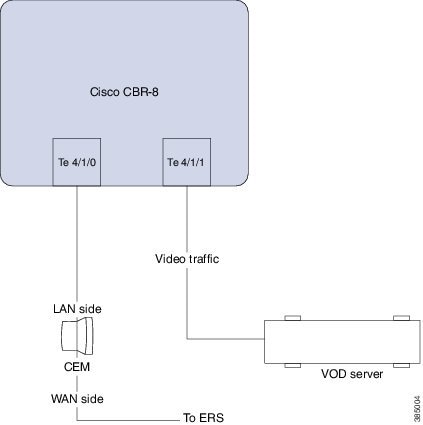
The PME Video On Demand system integrates the encrypted VOD content within an Arris digital cable headend. A VOD system provides the clear content while the Cisco cBR-8 and CEM are added to provide encryption. The details on the usage of the CEM are described in this chapter. Every MSO site should have the CEM application, which is the single entity connecting to the Arris Encryption Renewal System (ERS). All the Cisco cBR-8s on this MSO site should connect to this CEM.

Prerequisites for VPME

To enable VPME encryption, the connection to the CEM should be configured. VPME is a licensed feature and requires appropriate license on the chassis. The following connection should be configured:

  • The video traffic flow on the Ten Gigabit interface.

  • Table-based video sessions.

  • QAM PHY parameters for the physical QAM channel.

Restrictions for VPME

You can configure the line card in only one mode as the table-based session configuration and dynamic GQI-based sessions are mutually exclusive. Hence, PME and PowerKey encryption are also mutually exclusive modes at the line card level. For more details, see Configuring the Encryption Type on the Line Card section.

How to Configure Table-Based Video Session

Configuring Table-Based Video

Before You Begin

Before configuring table-based sessions, you must configure the physical and virtual constructs for Cisco cBR-8. You must also configure the Logical Edge Device (LED), Service Distribution Group (SDG), binding and Virtual Carrier Group (VCG).

The following is an example for LED configuration. In this example, assumes that the video traffic is routed via the input ports of Virtual Edge Input (VEI).

logical-edge-device pme_tbv id 1
protocol table-based
virtual-edge-input-ip 172.16.0.1 input-port-number 1
vcg pme_tbv
active

In the above example, protocol table-based indicates that this LED supports table-based sessions.

For more information, see the How to Configure the Logical Edge Devices section. For details related to D6 protocol, see the How to Configure the D6 Discovery Protocol section.

Configuring Table-Based Session : VEI Input Port-Based

To configure the table-based session based on Virtual Edge Input (VEI), complete the following procedure:

configure terminal 
cable video 
table-based 
vcg vcg-name 
rf-channel n-m 
session name {input-port number | bundle-id number} 
start-udp-port number num-sessions-per-qam number processing-type 
 {program | data } start-program number [repeat] jitter 
ms [cbr | vbr ] 
exit 

The table-based keyword is the root keyword. The entire table-based configuration should be under this keyword. Within this, the configuration is separated based on the VCG. Within each VCG, the configuration can be created for each QAM channel.

  • Processing-type

    • Remap—Configures VoD sessions as remap.

    • Data—Configure video streams that are not dejittered, and remapped. For example, Beacons, carousel, and so on.

  • Repeat—Repeats the program number across QAM channels.

Example:

The following is an example in which two sessions are created on all QAM channels from 20 to 22.

configure terminal
cable video
table-based
vcg pme_tbv
rf-channel 20-22
session bago_tbv input-port 1 start-udp-port 49152 num-sessions-per-qam 2 processing-type remap start-program 32 jitter 150 cbr
exit

The following is an example in which one session is created on each QAM channel.

configure terminal
cable video
table-based
vcg pme_tbv2
rf-channel 23
session pme_tbv input-port 1 start-udp-port 50152 num-sessions-per-qam 1 processing-type remap start-program 5 jitter 150 cbr
rf-channel 24
session pme_tbv input-port 1 start-udp-port 50153 num-sessions-per-qam 1 processing-type remap start-program 5 jitter 150 cbr
exit

Configuring Table-Based Session :VEI Bundle-Based

Before You Begin

  • Create two or more VEIs.

  • Bundle the VEIs.

For more details, see Virtual Edge Input Bundling section.

To configure the VEI bundled table-based session, complete the following procedure:

configure terminal 
cable video 
table-based 
vcg vcg-name 
rf-channel n-m 
session name  bundle-id number start-udp-port 
number num-sessions-per-qam number processing-type  
{program | passthru | data } start-program number
 [repeat] jitter ms [cbr | vbr ] 
exit 

Example:

The following is an example in which a session is created for VEI bundle (10) .

configure terminal
cable video
table-based
vcg pme_vcg
rf-channel 20-21
session tbv bundle-id 10 start-udp-port 49152 num-sessions-per-qam 2 processing-type remap start-program 1 repeat jitter 100 vbr
exit
Virtual Edge Input Bundling

To create and bundle the VEIs, complete the following procedure:

configure terminal 
cable video 
logical-edge-device name 
protocol table-based  
virtual-edge-input-ip ip address input-port-number number 
vcgvcg-name 
vei-bundle id input-port-number number 
active 
exit 

Example:

The following is an example in which a bundle (10) is created with two input ports (1 and 2) each with distinct IP address.

configure terminal
cable video
logical-edge-device pme_led id 1
protocol table-based
virtual-edge-input-ip 172.16.0.1 input-port-number 1
virtual-edge-input-ip 172.16.0.1 input-port-number 2
vcg pme_vcg
vei-bundle 10 input-port-number 1,2
active
exit

Verifying Table-Based Video Configuration

Verify All Sessions Configured on an LED

To verify all the sessions configured on a particular LED, use the show cable video session logical-edge-device id number command as shown in the example below:
show cable video session logical-edge-device id 1
Total Sessions = 6

Session Output Streaming Session Destination UDP   Output  Input      Output Input   Output  Encrypt Encrypt Session
Id      Port   Type      Type                Port  Program State      State  Bitrate Bitrate Type    Status  Name
-----------------------------------------------------------------------------------------------------------------------------------
1048576  1      Remap    UDP     174.21.1.1  49152 32      ACTIVE-PSI ON     1718234 1702594 CLEAR    -      bago_tbv.1.0.1.20.49152
1048577  1      Remap    UDP     174.21.1.1  49153 33      ACTIVE-PSI ON     1718631 1702594 CLEAR    -      bago_tbv.1.0.1.20.49153
1048578  2      Remap    UDP     174.21.1.1  49154 34      ACTIVE-PSI ON     1717832 1702977 CLEAR    -      bago_tbv.1.0.1.21.49154
1048579  2      Remap    UDP     174.21.1.1  49155 35      ACTIVE-PSI ON     1717322 1702977 CLEAR    -      bago_tbv.1.0.1.21.49155
1048580  3      Remap    UDP     174.21.1.1  49156 36      ACTIVE-PSI ON     1718697 1702959 CLEAR    -      bago_tbv.1.0.1.22.49156
1048581  3      Remap    UDP     174.21.1.1  49157 37      ACTIVE-PSI ON     1717542 1702959 CLEAR    -      bago_tbv.1.0.1.22.49157

verify the summary of the session details

To verify the summary of the session details at a LED level, use the show cable video session logical-edge-device id number summary command as shown in the example below:

show cable video session logical-edge-device id 1 summary
Video Session Summary:

Active    : 6        Init      : 0        Idle      : 0
Off       : 0        Blocked   : 0        PSI-Ready : 6
UDP       : 6        ASM       : 0        SSM       : 0
Remap     : 6        Data      : 0        Passthru  : 0
Total Sessions: 6

Verify QAM PHY Parameters of RF-channel

To verify the QAM PHY parameters of RF-channel that are configured on the RF port, which is controller Integrated-Cable 7/0/0, use the show controllers integrated-Cable slot/bay/portrf-channel n-m command as shown in the example below:

show controllers integrated-Cable 7/0/0 rf-channel 0-95 
Chan State Admin Frequency  Type   Annex Mod  srate Interleaver  dcid  power  output
 0     UP   UP   93000000   VIDEO   B    256   5361  I32-J4       -    34     NORMAL
 1     UP   UP   99000000   VIDEO   B    256   5361  I32-J4       -    34     NORMAL
 2     UP   UP   105000000  VIDEO   B    256   5361  I32-J4       -    34     NORMAL
 3     UP   UP   111000000  VIDEO   B    256   5361  I32-J4       -    34     NORMAL
 4     UP   UP   117000000  VIDEO   B    256   5361  I32-J4       -    34     NORMAL
 5     UP   UP   123000000  VIDEO   B    256   5361  I32-J4       -    34     NORMAL
 6     UP   UP   129000000  VIDEO   B    256   5361  I32-J4       -    34     NORMAL
 7     UP   UP   135000000  VIDEO   B    256   5361  I32-J4       -    34     NORMAL
 8     UP   UP   141000000  VIDEO   B    256   5361  I32-J4       -    34     NORMAL
 9     UP   UP   147000000  VIDEO   B    256   5361  I32-J4       -    34     NORMAL
 10    UP   UP   153000000  VIDEO   B    256   5361  I32-J4       -    34     NORMAL

Output State is OFF

Procedure

Step 1

Verify the video traffic using the show cable video session logical-edge-device id 1 command. In the below example, the output state is OFF. This value confirm that there is no output traffic.


Session Output Streaming Session Destination UDP   Output  Input Output Input   Output  Encrypt Encrypt Session
Id      Port   Type      Type                Port  Program State State  Bitrate Bitrate Type    Status  Name
------------------------------------------------------------------------------------------------------------------------------
1048582    1   Remap     UDP     172.16.0.1  49152 32      OFF   OFF    0       0       PME     Pending bago_tbv.1.0.1.20.49152
1048583    1   Remap     UDP     172.16.0.1  49153 33      OFF   OFF    0       0       PME     Pending bago_tbv.1.0.1.20.49153
1048584    2   Remap     UDP     172.16.0.1  49154 34      OFF   OFF    0       0       PME     Pending bago_tbv.1.0.1.21.49154
1048585    2   Remap     UDP     172.16.0.1  49155 35      OFF   OFF    0       0       PME     Pending bago_tbv.1.0.1.21.49155
1048586    3   Remap     UDP     172.16.0.1  49156 36      OFF   OFF    0       0       PME     Pending bago_tbv.1.0.1.22.49156
1048587    3   Remap     UDP     172.16.0.1  49157 37      OFF   OFF    0       0       PME     Pending bago_tbv.1.0.1.22.49157
Step 2

Verify if the RF output of the controller is shut using the show cable video integrated-cable command.

Router#show cable video integrated-cable 8/0/0

Integrated TSID ONID Output Physical    Admin Operational Virtual-Carrier Service-Distribution Logical-Edge Encryption Total
Cable                Port   QAM ID      State State       -Group Name     -Group Name          -Device Name Capable    Sessions
-------------------------------------------------------------------------------------------------------------------------------
8/0/0:20   1     0    1    unavailable  OFF   DOWN        pme_tbv        pme_tbv               pme_tbv      pme        2
8/0/0:21   2     0    2    unavailable  OFF   DOWN        pme_tbv        pme_tbv               pme_tbv      pme        2
8/0/0:22   3     0    3    unavailable  OFF   DOWN        pme_tbv        pme_tbv               pme_tbv      pme        2
8/0/0:23   4     0    4    unavailable  OFF   DOWN        pme_tbv        pme_tbv               pme_tbv      pme        2
8/0/0:24   5     0    5    unavailable  OFF   DOWN        pme_tbv        pme_tbv               pme_tbv      pme        0
  1. If the RF output of the controller is shut, you must unshut the port. This action changes the status as ON for the corresponding QAMs. You can verify the state using the show cable video integrated-cable command.

    Router#show cable video integrated-cable 8/0/0
    
    Integrated TSID ONID Output Physical Admin Operational Virtual-Carrier Service-Distribution Logical-Edge Encryption Total
    Cable                Port   QAM ID   State State       -Group Name     -Group Name          -Device Name Capable    Sessions
    ----------------------------------------------------------------------------------------------------------------------------
    8/0/0:20   1     0    1     48       ON    UP           pme_tbv        pme_tbv             pme_tbv       pme        2
    8/0/0:21   2     0    2     49       ON    UP           pme_tbv        pme_tbv             pme_tbv       pme        2
    8/0/0:22   3     0    3     50       ON    UP           pme_tbv        pme_tbv             pme_tbv       pme        2
    8/0/0:23   4     0    4     51       ON    UP           pme_tbv        pme_tbv             pme_tbv       pme        2
    8/0/0:24   5     0    5     24       ON    UP           pme_tbv        pme_tbv             pme_tbv       pme        2
    
    
Step 3

Verify the JIB channel number for a specific QAM channel using the show cable video integrated-cable command.

Router#show controllers integrated-Cable 7/0/0 rf-channel 21 verbose

Chan State Admin Frequency  Type   Annex Mod  srate Interleaver  dcid  power  output
 21    UP   UP   219000000  VIDEO   B    256   5361  I32-J4       -    34     NORMAL
 Qam profile: 1
 Spectrum Inversion: Off
 Frequency Lane: 1  Block: 3  index: 6
 Resource status:   OK
 License: granted <01:07:01 EDT Feb 19 2016>
 QAM Replication:
    Group ID: 57344 (Pilot)
    Slot group ID: 0
    Members: 7/0/0:21 (P) 7/0/1:21  7/0/2:21  7/0/3:21

   Channel Replication Status: Up
 JIB channel number: 21
Chan Pr EnqQ  Pipe  RAF   SyncTmr Vid Mac            Video Primary DqQ  TM Mpts Sniff
  21 --    21     0  6880       0   1 0000.0000.0000     1       0   21  0    5 NO 86
Grp  Prio P  Prate Phy0-ctl Phy1-ctl Enable Tun-Id  L2TPv3_Ses_id
   2    0  0     1        1        0   TRUE       0      2
Chan   Qos-Hi   Qos-Lo    Med-Hi   Med-Lo    Low-Hi   Low-Lo
  21    32774    16384     32768    16384     65536    32768
Chan  Med Low TB-neg Qos_Exc  Med_Xof  Low_Xof    Qdrops(H-M-L)  Pos Qlen(Hi-Med-lo) Fl
   21   0   0      0       0        0        0    0    0    0  N 23808     0 11656  0
  DSPHY Register Local Copy: QPRHI = c0005564, QPRLO = 216ab0
  DSPHY Register Local Copy Vaddr = 800002e4, qam2max_mapping = 80000015
  DSPHY Register Local Copy: SPR ID = 15, SPR Mapping= c200000b
  Last read from HW: Fri Feb 19 01:07:57 2016
   QPRHI = c0005564, QPRLO = 216ab0, SPR = c200000b SPRMAPING c0000205 Q2Max 80000015
  Last time read spr rate info from HW: Fri Feb 19 03:06:43 2016
    SPR ID 21, rate value in kbps 3463, overflow count 0, underflow count 0

Output Status is Idle or Pending

Procedure

Step 1

Verify the video traffic. In the below example, the input bitrate is zero, and the input state is IDLE / OFF. These values confirm that there is no input traffic.


Router#sh cable video session logical-edge-device id 1
Total Sessions = 6

Session Output Streaming Session Destination UDP   Output  Input Output Input   Output  Encrypt Encrypt Session
Id      Port   Type      Type                Port  Program State State  Bitrate Bitrate Type    Status  Name
------------------------------------------------------------------------------------------------------------------------------
1048588    1   Remap     UDP     172.16.0.1  49152 32      IDLE  PENDING 0      0       PME     Pending bago_tbv.1.0.1.20.49152
1048589    1   Remap     UDP     172.16.0.1  49153 33      IDLE  PENDING 0      0       PME     Pending bago_tbv.1.0.1.20.49153
1048590    2   Remap     UDP     172.16.0.1  49154 34      IDLE  PENDING 0      0       PME     Pending bago_tbv.1.0.1.21.49154
1048591    2   Remap     UDP     172.16.0.1  49155 35      IDLE  PENDING 0      0       PME     Pending bago_tbv.1.0.1.21.49155
1048592    3   Remap     UDP     172.16.0.1  49156 36      IDLE  PENDING 0      0       PME     Pending bago_tbv.1.0.1.22.49156
1048593    3   Remap     UDP     172.16.0.1  49157 37      IDLE  PENDING 0      0       PME     Pending bago_tbv.1.0.1.22.49157
Step 2

Verify details of the video traffic over the mid plane interface through which traffic is routed to the video data plane on the line card. The mid plane is specific to the line-card slot. On subsequent trials, the output packet count should keep increasing. You can verify the output packet count using the show interfaces video command.


Router#show interfaces video 7/0/0 accounting

Video7/0/0
                Protocol    Pkts In   Chars In   Pkts Out   Chars Out
                      IP          0          0   2211315936 2653579123200
                 DEC MOP          0          0         12        756
                     ARP          0          0          4        112

Video7/0/0
                Protocol    Pkts In   Chars In   Pkts Out   Chars Out
                      IP          0          0   2220252160 2664302592000
                 DEC MOP          0          0         12        756
                     ARP          0          0          4        112
Step 3

If the packet count is not increasing, verify the 10 GigE physical interface through which the video traffic is fed to the chassis using the show interfaces command. In the below example, the video traffic is fed through the 10GigE interface 4/1/0 and the counter for packets keeps incrementing.


Router#show interfaces tenGigabitEthernet 4/1/0 accounting
TenGigabitEthernet4/1/0
                Protocol    Pkts In   Chars In   Pkts Out  Chars Out
                   Other         15       1155       1814     109078
                      IP 8038262210 9404766785700       0          0
                 DEC MOP         15       1155         14       1078
                     ARP          0          0          1         60
Router#show interfaces tenGigabitEthernet 4/1/0 accounting
TenGigabitEthernet4/1/0
                Protocol    Pkts In   Chars In   Pkts Out  Chars Out
                   Other         15       1155       1816     109198
                      IP 8047199112 9415222959870       0          0
                 DEC MOP         15       1155         14       1078
                     ARP          0          0          1         60

Input State is Active and not Active PSI

If the input state is Active and the input PSI information is not detected, verify the input PMT information section for this particular session.

Procedure

Verify the details of a particular video session, using the show cable video session logical-edge-device id led-id session-id id command.


Router#show cable video session logical-edge-device id 1 session-id 1048599
Session Name        : bago_tbv.1.0.1.22.49157
Session Id:         : 1048599
Creation Time:      : Thu Feb 18 18:21:25 2016

Output Port         : 3
TSID                : 3
ONID                : 0
Number of Sources   : 1
  Destination IP    : 172.16.0.1
  UDP Port          : 49157
Config Bitrate      : 2000000
Jitter              : 150 ms
Processing Type     : Remap
Stream Rate         : CBR
Program Number      : 37
Idle Timeout        : 250 msec
Init Timeout        : 1000 msec
Off Timeout         : 60 sec
Encryption Type     : PME
Encryption Status   : Encrypted

Input Session Stats:
====================
  State: ACTIVE-PSI, Uptime: 0 days 00:01:01
  IP Packets: In 12202, RTP 0, Drop 0
  TP Packets: In 69979, PCR 2447, PSI 1323, Null 3233, Unreference 153
  Errors: Discontinuity 8, Sync loss 0, CC error 0, PCR Jump 17,
          Underflow 0, Overflow 0, Block 0
  Bitrate: Measured 1716626 bps, PCR 1800140 bps

Output Session Stats:
=====================
  State: ON, Uptime: 0 days 00:01:01
  TP Packets: In 70535, PCR 2440, PSI 1320,
              Drop 910, Forward 68305, Insert 1752
  Errors: Info Overrun 0, Info Error 0, Block 0, Overdue 0,
          Invalid Rate 0, Underflow 0, Overflow 0
  Bitrate: Measured 1723591 bps

PAT Info:
=========
  Version 0, TSID 1, len 20, section 0/0
  Program 0: NIT 16
  Program 1: PMT 8020

Input PMT Info:
===============
  Program 1, Version 0, PCR 8000, Info len 0
  PID 8000: Type 2, Info len 5, (desc 2 len 3)
  PID 8001: Type 129, Info len 17, (lang eng), (desc 5 len 4), (desc 129 len 3)

Output PMT Info:
================
  Program 37, Version 1, PCR 273, Info len 6, (CA SYS-ID 18249, PID 303)
  PID 273: Type 2, Info len 5, (desc 2 len 3)
  PID 274: Type 129, Info len 17, (lang eng), (desc 5 len 4), (desc 129 len 3)

Output PID Map:
===============
  PID 8000 -> 273
  PID 8001 -> 274
  PID 8020 -> 272


Abnormalities on the Output

If there are any abnormalities in the output such as macro blocks, ans so on, verify if there are any issues such as CC errors or PCR errors in the MPEG packet.

Verify the session details, using the show cable video session logical-edge-device id led-id session-id id command. This command displays errors for both input session stats and output session stats.

Configuring CEM Connectivity for PME Encryption

This section explains how to configure the connectivity to the external CEM and enforce PME encryption on the line card.

Only one device from the MSO site can communicate with the Encryption Renewal System (ERS) and obtain the latest ECM templates. The CEM communicates with the ERS and sends the ECM templates to the Cisco Edge QAM devices in the MSO site.

You can configure the following:

  • VODS-ID—IDs assigned by CCAD/ARRIS to the MSO site. The configured VODS-ID on the Cisco cBR-8 and the CEM must be same.

  • CEM IP—Interface IP of the Windows/Linux system through which the CEM can be reached by Cisco cBR-8.

  • CEM Port—Port number on which the CEM listens for connections from the Cisco cBR-8.

  • Management Interface—Source IP address of the cBR-8 virtual interface through which the connection must be established with the CEM server.


Note

There can be only one entry for VODS-ID, CEM IP, CEM Port, and Management Interface IP. If you configure any new values for these parameters, the previous configuration is cleared. You can clear the configurations using the 'no' form of the command.

Configuring VODS-ID

To configure the VODS-ID of the CEM, perform the following steps:
enable 
configure terminal 
cable video 
encryption  
pme vodsid id  
exit 

Configuring CEM IP and Port

To configure the CEM IP and port of the CEM, perform the following steps:
enable 
configure terminal 
cable video 
encryption  
pme cem ip-address tcp_port  
exit 

Configuring Management IP

To configure the PME management IP address to establish CEM connection, perform the following steps:

The virtual port group must be configured before configuring the management IP. For more information, see the Configuring the VirtualPortGroup Interface section.
enable 
configure terminal 
cable video 
encryption  
pme mgmt-ip ip-address  
exit 

Verifying CEM Connectivity

To verify the connection status of PME, use the show cable video encryption pme status command as shown in the following example:


Router#show cable video encryption pme status 
PME Connection Status:
VODS-ID : 111
CEM IP : 1.200.1.163
CEM Port : 5000
Local Mgmt IP : 1.24.2.6
Local Port : 50394
CEM Connection State : Connected
Count of ECMs recd : 2

Connectivity with CEM is Lost

Procedure

Step 1

If the CEM connection status is Not Connected, verify the VODS-ID, CEM IP, CEM port and local Mgmt IP address parameters using the show cable video encryption pme status command.


Router#show cable video encryption pme status  
PME Connection Status:
======================
VODS-ID              : 111
CEM IP               : 1.200.1.163
CEM Port             : 5000
Local Mgmt IP        : 1.35.2.5
Local Port           : 0
CEM Connection State : Not Connected
Step 2

If the PME connection parameters are valid, ensure there is route from the Cisco cBR-8's Virtual management iinterface to the CEM by using the ping command. Ping the CEM IP address from the virtualPortGroup 0 on which the management IP is created.


Router#ping 1.200.1.163 source virtualPortGroup 0
Type escape sequence to abort.
Sending 5, 100-byte ICMP Echos to 1.200.1.163, timeout is 2 seconds:
Packet sent with a source address of 1.35.2.1
!!!!!
Success rate is 100 percent (5/5), round-trip min/avg/max = 1/1/1 ms
Step 3

Verify the alarms in the logs for any connectivity loss.

Feb 18 18:28:12.053 IST: %VEMAN-3-CEM_CONNECTION_LOST: CLC4: sup_veman:  Alarm Set: CEM Connection Lost: Connection closed by peer-1.200.1.163:5000


How to Configure VPME Encryption

Enforcing Data Stream Encryption Type

Before You Begin

Configure the Virtual Carrier Group (VCG) to setup an encrypted session. For more details, see Configuring Virtual Carrier Group section.

To configure the encryption type for a VOD session, perform the following steps:

enable
configure terminal 
cable video 
encryption  
linecard slot/bay ca-system [dvb | pme | powerkey] scrambler scrambler-type [dvb-csa | des | dvs042] 
exit 

Configuring Virtual Carrier Group

To configure the Virtual Carrier Group (VCG) for setting up an encrypted session, perform the following steps:

enable 
configure terminal 
cable video 
encryption  
virtual-carrier-group name[idnumber] 
rf-channel start-channel number-end-channel number tsid start-tsid-end-tsid output-port-number start-num-end-num 
virtual-edge-input ipaddr input-port-number port-number 
encrypt 
exit 

Verifying VPME Encryption Configuration

  • To verify the encryption configurations, use the show cable video encryption linecard [all | slot number] command as shown in the following example:

    
    Router#show cable video encryption linecard 7/0
    Line card: 7/0
    CA System Scrambler
    ====================================
    PME dvs-042
    
    
  • To verify the encryption status of all sessions on an LED, use the show cable video session logical-edge-device id id command as shown in the following example:

    
    Router#show cable video session logical-edge-device id 1
    Total Sessions = 6
    
    Session Output Streaming Session Destination UDP   Output  Input      Output Input   Output  Encrypt Encrypt   Session
    Id      Port   Type      Type                Port  Program State      State  Bitrate Bitrate Type    Status    Name
    --------------------------------------------------------------------------------------------------------------------------------------
    1048582 1      Remap     UDP     172.16.0.1  49152 32      ACTIVE-PSI ON     996413  981109  PME     Encrypted bago_tbv.1.0.1.20.49152
    1048583 1      Remap     UDP     172.16.0.1  49153 33      ACTIVE-PSI ON     1004787 981246  PME     Encrypted bago_tbv.1.0.1.20.49153
    1048584 2      Remap     UDP     172.16.0.1  49154 34      ACTIVE-PSI ON     995088  984011  PME     Encrypted bago_tbv.1.0.1.21.49154
    1048585 2      Remap     UDP     172.16.0.1  49155 35      ACTIVE-PSI ON     993061  984051  PME     Encrypted bago_tbv.1.0.1.21.49155
    1048586 3      Remap     UDP     172.16.0.1  49156 36      ACTIVE-PSI ON     994238  988617  PME     Encrypted bago_tbv.1.0.1.22.49156
    1048587 3      Remap     UDP     172.16.0.1  49157 37      ACTIVE-PSI ON     1004658 988602  PME     Encrypted bago_tbv.1.0.1.22.49157


  • To verify the various sessions, which use the PME modules that are loaded on a specific line-card, use the show cable video encryption pme linecard slot/bay session 1-65535 | all | summary command as shown in the example below:

    
    Router#show cable video encryption pme linecard 7/0 session all
    Count of ECMG Streams: 4
    ==================== ECMG Stream DATA ========================
    Stream
    ID num EcmId CP# CwE CPDur NomCPD EcmRqst EcmRsp
    ---------- ---------- ---- --- ----- ------ ---------- ----------
    0020(0032) 0020(0032) 0002 0 0 40000 7 2
    0021(0033) 0021(0033) 0002 0 0 40000 7 2
    0040(0064) 0040(0064) 0002 0 0 40000 7 2
    0041(0065) 0041(0065) 0002 0 0 40000 7 2
    
    Router#show cable video encryption pme linecard 7/0 session 32
    Stream 32, session 7681 is active
    Stream number = 32 Session number = 7681
    ECM requests = 8 ECM replies = 2
    ECM ID = 32 CryptoPeriod num = 2
    CP duration = 0 Nominal duration = 40000
    CA transfer mode = 1 Stream status = No
    Error Blob details
    
    Router#show cable video encryption pme linecard 7/0 session summary
    Currently active streams:
    Active = 4
    ECM req/resp mismatch = 4
    ECM req, all streams = 32
    ECM resp, all streams = 8
    Since last reset:
    Sessions created = 4
    Sessions deleted = 0
    ECMs received =2 
    ECMs discarded = 0


No PMT at the Output

Procedure

Step 1

Verify the encryption status using the show cable video session logical-edge-device id command. If the encrypt status is shown as ca-waiting, then PMT is withheld.


Router#show cable video session logical-edge-device id 1
Total Sessions = 6

Session Output Streaming Session Destination UDP   Output  Input      Output Input   Output  Encrypt Encrypt    Session
Id      Port   Type      Type                Port  Program State      State  Bitrate Bitrate Type    Status     Name
--------------------------------------------------------------------------------------------------------------------------------------
1048582 1      Remap     UDP     172.16.0.1  49152 32      ACTIVE-PSI PENDING 996413 981109  PME     ca-waiting bago_tbv.1.0.1.20.49152

Step 2

Verify if the ECM count is zero using the show cable video encryption pme status command.


Router#show cable video encryption pme status
PME Connection Status:
VODS-ID : 111
CEM IP : 1.200.1.163
CEM Port : 5000
Local Mgmt IP : 1.24.2.6
Local Port : 50394
CEM Connection State : Connected
Count of ECMs recd : 0
Step 3

Verify if the ECM request or response count is 0 using the show cable video encryption pme linecard slot/bay session summary command.


Router#show cable video encryption pme linecard 7/0 session summary
Currently active streams:
Active = 4
ECM req/resp mismatch = 4
ECM req, all streams = 32
ECM resp, all streams = 8
Since last reset:
Sessions created = 4
Sessions deleted = 0
ECMs received =2 
ECMs discarded = 0


Configuration Examples For VPME Encryption

The following example shows running output for a PME configuration:

cable video

mgmt-intf virtualPortGroup 0

virtual-carrier-group pme_tbv
encrypt
service-type narrowcast
rf-channel 20-24 tsid 1-5 out 1-5

service-distribution-group pme_tbv
rf-port integrated-cable 7/0/0

bind-vcg
vcg pme_tbv sdg pme_tbv

encryption
linecard 7/0 ca-system pme scrambler dvs
pme vodsid 111
pme cem 1.200.1.163 5000
pme mgmt-ip 1.25.2.6

logical-edge-device pme_tbv
protocol table-based
virtual-edge-input-ip 174.101.1.1 input 1
vcg pme_tbv 
active

table-based
vcg vcg_replication
rf-channel 21-31
session pme_tbv1 in 1 start-udp-port 49152 num-sessions-per-qam 2 processing-type remap start-program 32 jitter 150 cbr
session pme_tbv2 in 1 start-udp-port 50001 num-sessions-per-qam 2 processing-type remap start-program 64 jitter 150 cbr

Use Cases or Deployment Scenarios

Topology

A typical topology for CEM connectivity is shown below:

Feature Information for Table-Based Video and VPME Encryption

Use Cisco Feature Navigator to find information about the platform support and software image support. Cisco Feature Navigator enables you to determine which software images support a specific software release, feature set, or platform. To access Cisco Feature Navigator, go to the https://cfnng.cisco.com/ link. An account on the Cisco.com page is not required.


Note

The following table lists the software release in which a given feature is introduced. Unless noted otherwise, subsequent releases of that software release train also support that feature.


Table 1. Feature Information for Table-Based Video and VPME Encryption

Feature Name

Releases

Feature Information

Table-Based Video and VPME Encryption

Cisco IOS XE Everest 16.6.1

This feature was integrated on the Cisco cBR Series Converged Broadband Routers.