How to Use Cisco Smart PHY

This section describes how to use the Cisco Smart PHY application:

Configure Cisco cBR for Smart PHY Application

Enable Logging

Enable logging to Cisco Smart PHY and set LCHA Traps to Smart PHY to ensure that the Smart PHY state is cBR-8 LCHA aware.

configure terminal
logging host <Smart PHY Worker node Virtual IP Address> transport [tcp|udp] port 8514
logging trap informational
cable logging layer2events

Configure Cable Service Profile-Group

Configure the Cable Service Profile-Group on the Cisco cBR router. The following is a sample of how to configure the Service Profile-Group:


Note

The number for US bonding groups should be a 2 or 4.


cable profile mac-domain test_MD
 cable ip-init dual-stack
 cable privacy accept-self-signed-certificate
 cable privacy skip-validity-period
!
!
cable profile wideband-interface test_WB
 cable downstream attribute-mask 80000001
!
!
cable profile downstream test_DS
 cable rf-bandwidth-percent 20
!
!
cable profile service-group test_SG1
 cable bundle 2
 mac-domain 0 profile test_MD
  downstream sg-channel 0-23 profile test_DS
  upstream 0 sg-channel 0
  upstream 1 sg-channel 1
  upstream 2 sg-channel 2
  upstream 3 sg-channel 3
  upstream 4 sg-channel 4
  upstream 5 sg-channel 5
  us-bonding-group 1
   upstream 0
   upstream 1
   upstream 2
   upstream 3
  us-bonding-group 2
   upstream 2
   upstream 3
   upstream 4
   upstream 5
  
 wideband-interface 0 profile test_WB
  downstream sg-channel 0-23 rf-bandwidth-percent 20
Log In using a Browser


Note

Upgrade to Cisco Smart PHY 3.1.1, if the user interface (UI) is not available.


Procedure


Step 1

In the browser's address bar, enter https:// server_name :30604.

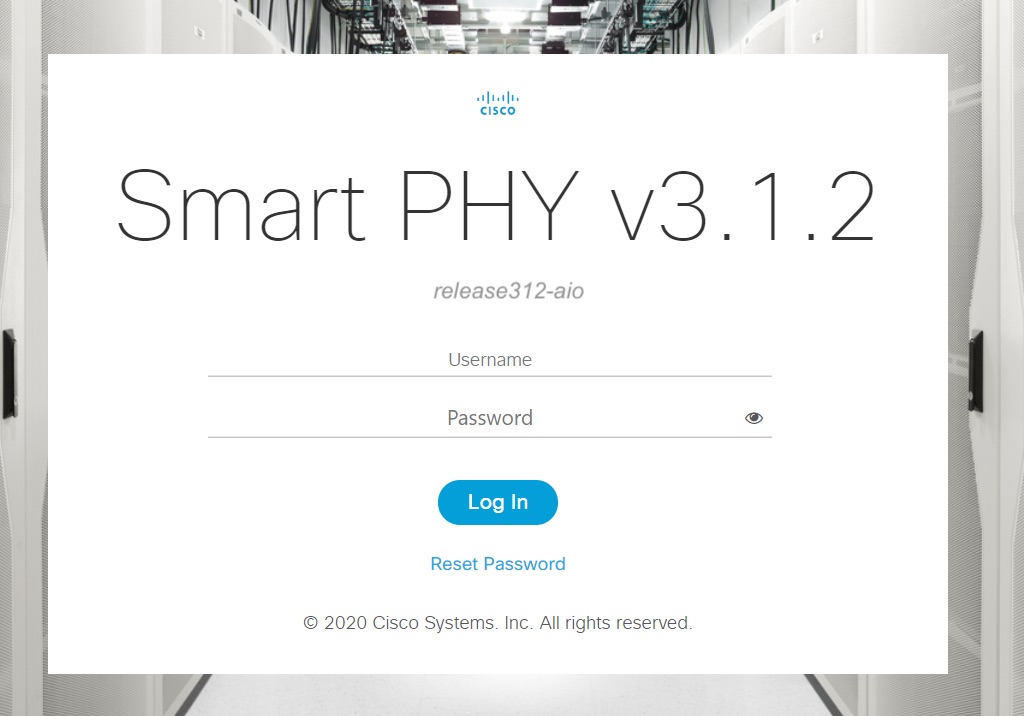
The Cisco Smart PHY web GUI displays the Login window. When you access Cisco Smart PHY for the first time, some browsers display a warning that the site is untrusted. When this happens, follow the prompts to add a security exception and download the self-signed certificate from the Cisco Smart PHY server. After you add the certificate, the browser accepts the Cisco Smart PHY server as a trusted site in all future login attempts.

Step 2

Log in using the default username admin and password admin.

If you are logging in for the first time, you are prompted to reset the password.

After resetting the password, log in using the new password.

Step 3

To exit the web GUI, close the browser window or click the settings icon in the top right corner and choose Log out.

Exiting a Cisco Smart PHY web GUI session does not shut down Cisco Smart PHY on the server.

If a system administrator stops the Cisco Smart PHY server during your Cisco Smart PHY session, your session ends. When the server restarts, you should start a new Cisco Smart PHY session.


Bring Up the RPD

Procedure


Step 1

Log into the Cisco Smart PHY application.

Go to https:// <HostOS_IP> :30604.

Step 2

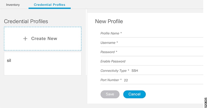
Create a Credential Profile.

  1. Choose Inventory > Credential Profiles.

  2. Enter the following details in the text fields.

    Field Name

    Description

    Profile Name

    Name of the Profile

    Username

    Username of the Cisco cBR router

    Password

    Password of the Cisco cBR router

    Connectivity Type

    SSH

    Port Number

    22

    Save/Delete/Cancel

    Use these buttons to complete your action

    Note 

    The Cisco Smart PHY application requires SSH to log in directly to the exec mode on the Cisco cBR-8 router.

  3. Click Save.

Step 3

Add the Cisco cBR router inventory and reference the credential profile.

Add a device manually or by importing from a CSV file.

  1. Choose Inventory > Inventory.

  2. To upload a CSV file, click the icon, select the file and click Import. The Import dialog box also holds a link to a sample CSV file which can be downloaded for reference. Make sure you save the edited file in CSV format.
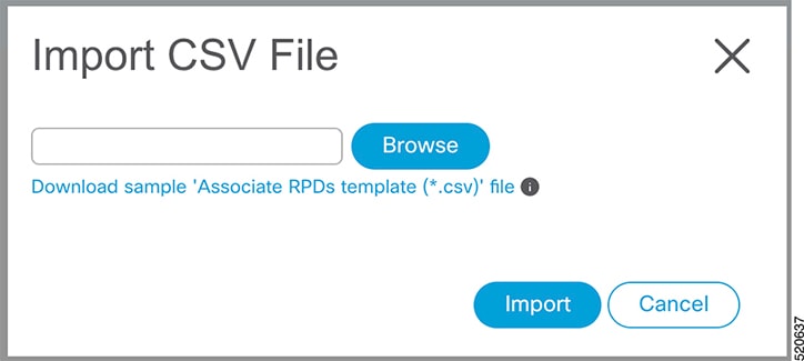
    The following values should be set for the Cisco cBR device.

    • Key Type—IP address

    • IP Address—IP address on the Cisco cBR router that can reach the Cisco Smart PHYapplication

    • Product Type—CBR-8-CCAP-CHASS

    • Credential Profile—Specify the credential profile

    Or

    To manually add a device, click the icon and provide the required information and save.
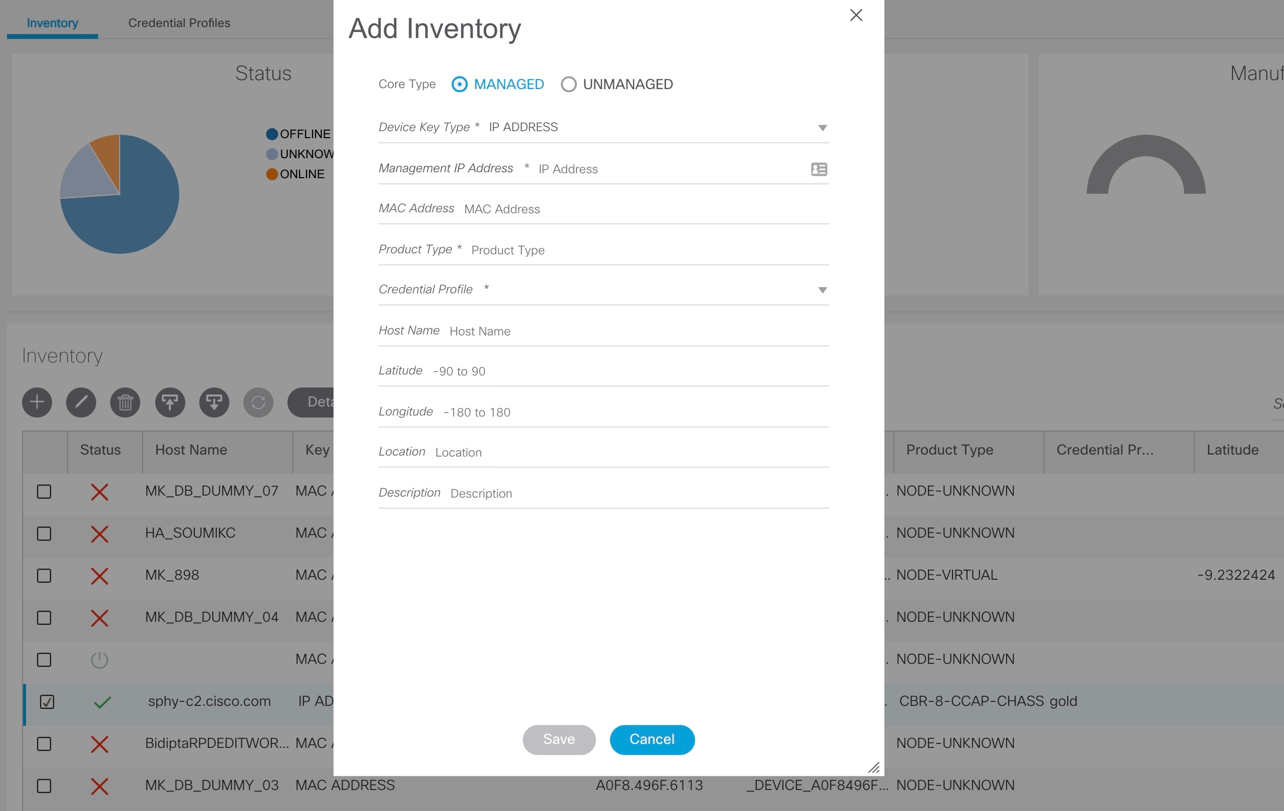
    Set the following values for the Cisco cBR device.

    • Key Type—IP address

    • IP Address—Management IP address on the Cisco cBR router

    • Product Type—CBR-8-CCAP-CHASS

    • Credential Profile—Specify the credential profile. Devices with the same credentials can use the same credential profile.

Step 4

Configure the Cisco cBR to send syslog messages to the Cisco Smart PHY application. The Cisco Smart PHY application uses syslog messages to monitor the state of the RPD on the Cisco cBR router. Run the following command on the Cisco cBR router:

logging host <Smart PHY interface connected to the Cisco cBR> transport udp port 8514
Step 5

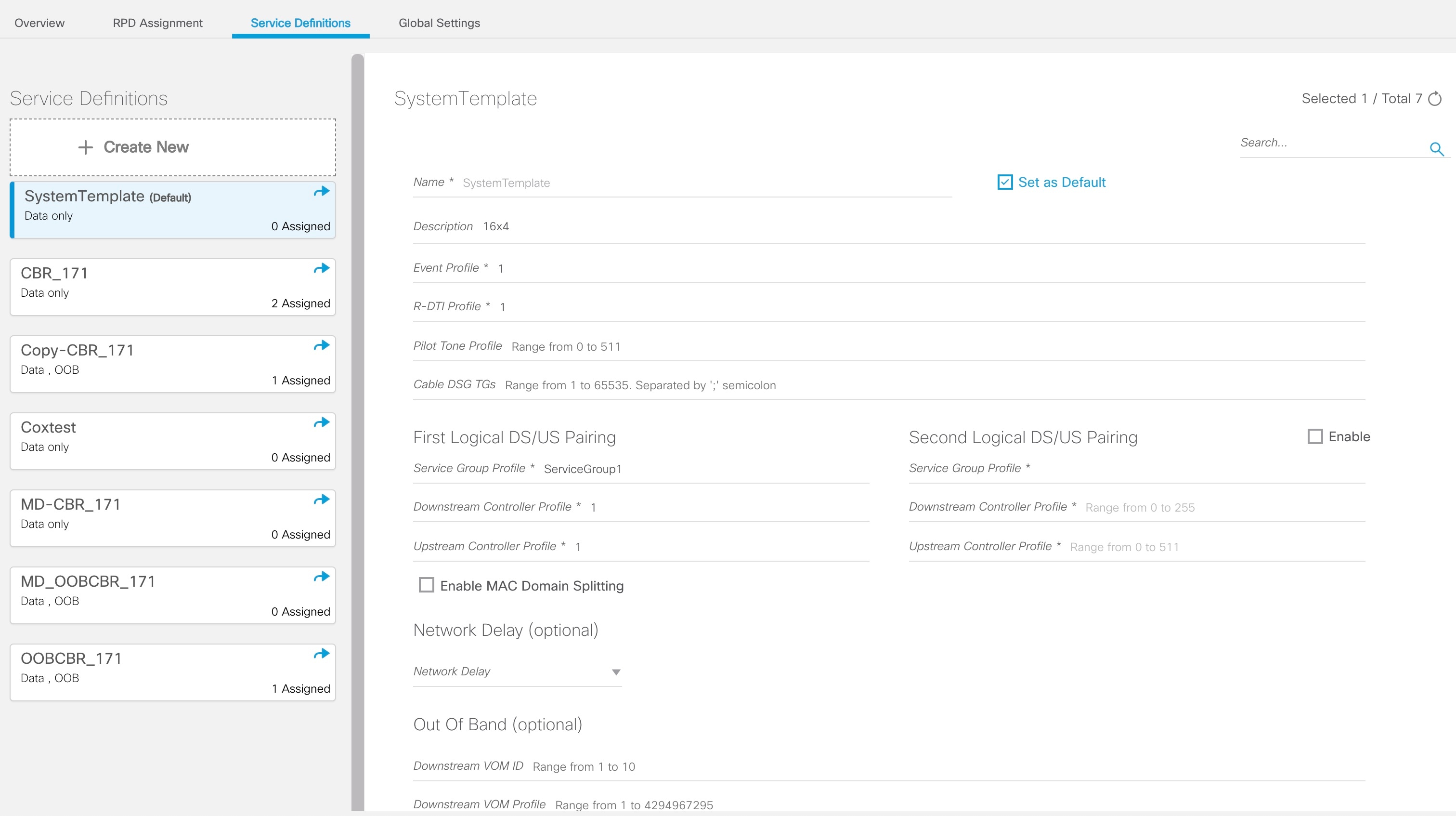
Create a Service Template.

Note 

Fields not marked as optional are mandatory.

  1. Choose Cable RPD Automation > Service Definitions.

  2. Specify Profiles as pre-configured on the Cisco cBR router.

    Name

    Description

    Event Profile

    RPD Event Profile Set

    R-DTI Profile

    Remote DOCSIS Timing Interface (R-DTI) Set

    Pilot Tone Profile

    Pilot tone profile.

    Cable DSG TGs

    DSG tag IDs.

    Primary Service

    Service Group Profile

    Pre-existing Cable Service Profile-Group on the CBR

    Enable MAC Domain Splitting

    Select the checkbox to split a MAC domain between two fiber-nodes that share the same downstream controller.

    Downstream Controller Profile

    Primary downstream CCAP controller profile.

    Upstream Controller Profile

    Primary upstream CCAP controller profile.

    Out Of Band

    Out-of-band profile parameters.

    Network Delay

    Network delay has two options:

    • DLM—System periodically measures the network latency between the CCAP core and the RPD, and dynamically updates the cable map advance. range is interval in seconds. The valid range for measuring DLM is 1 to 420 seconds.

      Measure only—Select to measure network latency between the CCAP core and the RPD. This option is not for updating the cable map advance. You can select this option for a service definition in use, but cannot deselect it.

    • Static—The cable map advance is adjusted by a fixed amount. The valid range is 30 to 100,000 microseconds.

      This range is the Converged Interconnect Network (CIN) delay in microseconds. CIN is the network between the CCAP core and RPD.

    You can change the network-delay range for a service definition in use.

    For more details, see DEPI Latency Measurement in the Service Template section in this document.

    Out Of Band

    Downstream VOM ID

    OOB 55-1 Downstream Virtual Out-of-Band Modulator (VOM) identification (ID).

    Downstream VOM Profile

    OOB 55-1 Downstream VOM profile.

    Upstream VARPD ID

    OOB 55-1 Upstream Virtual Advanced Return Path Demodulator (VARPD) ID.

    Upstream VARPD Profile

    OOB 55-1 Upstream VARPD profile for first logical downstream/upstream (DS/US) pairing.

    Second Upstream VARPD Profile

    OOB 55-1 Upstream VARPD profile for second logical downstream/upstream (DS/US) pairing.

    NDF/NDR

    Psuedowire Name (sic)

    NDF

    Narrowband digital forward (NDF) pseudowire name.

    Up to three pseudowire names, profile ID sets are supported. Values are applied to all downstream ports of the RPD.

    NDR

    NDR pseudowire name. Up to three pseudowire names, profile ID sets are supported per upstream port.

    Profile ID

    • NDF—NDF profile ID corresponding to the above NDF pseudowire.

    • NDR—NDR profile ID corresponding to above NDF pseudowire.

    NDR: Port

    Upstream port, Port 0 or Port 1, to apply Narrowband Digital Return (NDR) pseudowire name, profile set.

    Load Balance

    Paste the load balance XML text in the text field. Use the ntool to convert the XML configuration from the Cisco cBR router to the required XML format.

  3. Click Save.

Step 6

Pair an RPD with the RPD MAC address in the RPD assignment table.

If you are using the Smart PHY application on a mobile device, before you pair an RPD with the MAC address, ensure that you create a table entry for the RPD (RPD_NAME1) with the following details: RPD name, description, location, pairing with Cisco cBR-8 router, and service template.

After the initial installation of the RPD, the mobile application scans the RPD, gets an IP address, and contacts the Cisco Smart PHY application for provisioning as RPD_MAC1. You can also pair the RPD_NAME1 with the RPD_MAC1 when scanning the RPD using the mobile application.

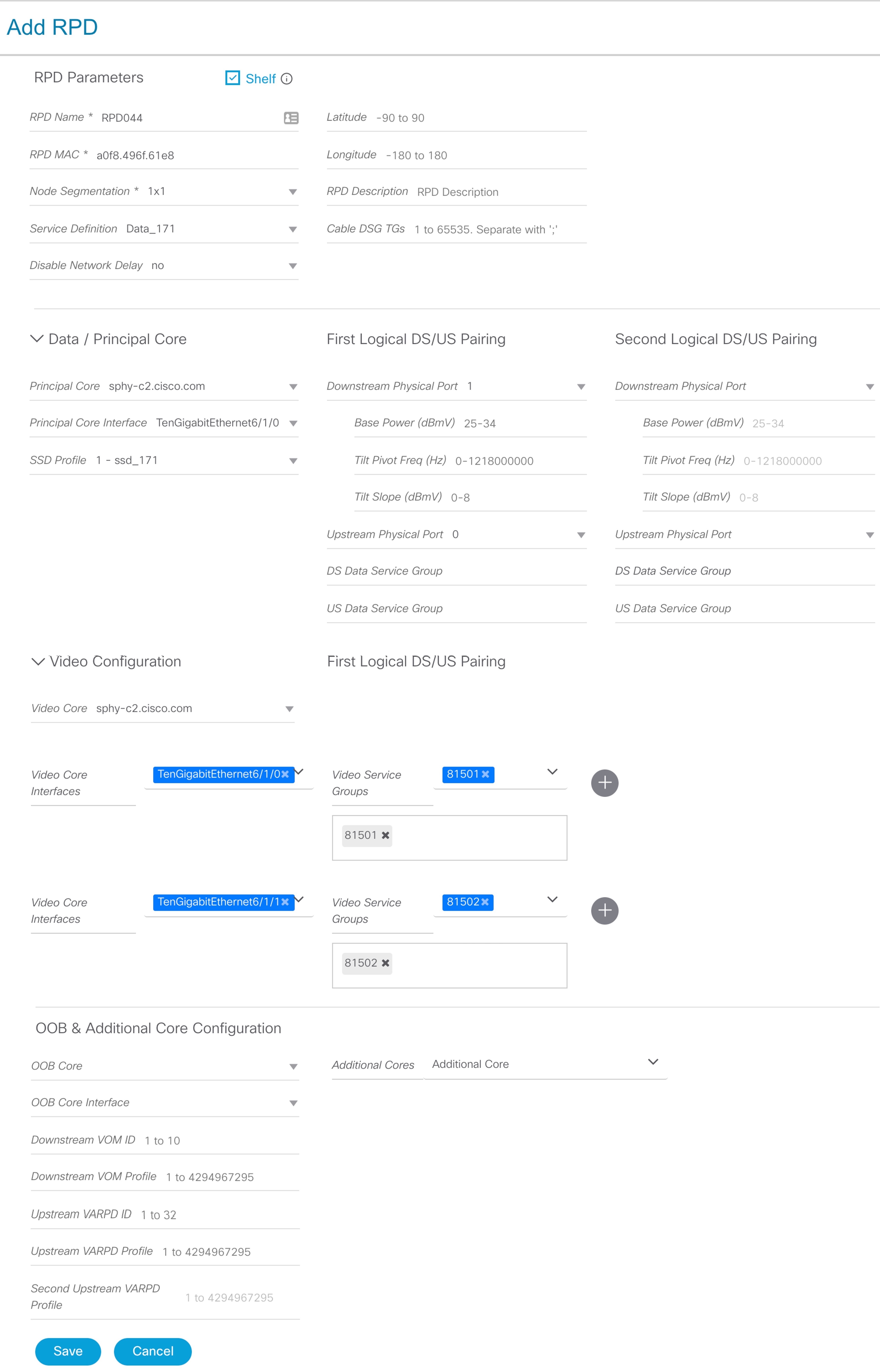
Adding RPD through a Web GUI

Note 

Fields with an asterisk is mandatory.

Add RPD devices through the Cable RPD Automation > RPD Assignment menu options and not through the Inventory menu.

  1. Choose Cable RPD Automation > RPD Assignment.

  2. RPD Assignment can be specified manually or by importing a CSV file.

    To upload a CSV file, click the icon, select the file and click Import.

    Or

    To specify RPD assignment manually, click Add or Edit.

    Field Name

    Description

    RPD Name

    Name for the RPD.

    This RPD name is also used in the cable rpd CLI command.

    RPD MAC Address

    MAC address of the RPD.

    Node Segmentation

    Node segmentation of the RPD: 1x1, 1x2, or 2x2.

    Service Definition

    Service Definition as created in the Service Definitions tab.

    CCAP Core

    Cisco cBR-8 broadband router to which RPD must connect for data, video, out-of-band (OOB) SCTE 55-1, and narrowband digital forward (NDF)/narrowband digital return (NDR) services.

    SSD Profile

    Solid State Device (SSD) profile details for image storage.

    Disable Network Delay

    The default is value is No.

    • No—Apply network delay from service definition to RPD.

    • Yes—Do not apply network delay from service definition to RPD.

    Changing this value to yes is service impacting, if the RPD’s assigned Service Definition/Template has network-delay configured.

    CCAP Core Interface

    Complete name of the TenGigabitEthernet DPIC Interface to be used for Data Service.

    Video Interfaces

    Complete names of the TenGigabitEthernet DPIC Interface to be used for Video Interfaces.

    Out of Band Interface

    Complete name of the TenGigabitEthernet DPIC Interface to be used for Out of Band 55-1

    Downstream VOM ID

    OOB 55-1 Downstream Virtual Out-of-Band Modulator (VOM) Identification (ID). If present, this value overrides the value from the Service Definition.

    Downstream VOM Profile

    OOB 55-1 Downstream VOM profile. If present, this value overrides the value from the Service Definition.

    Upstream VARPD ID

    OOB 55-1 Upstream Virtual Advanced Return Path Demodulator (VARPD) ID. If present, this value overrides the value from the Service Definition.

    Upstream VARPD Profile

    OOB 55-1 Upstream VARPD profile for first logical Downstream/Upstream (DS/US) pairing. If present, this value overrides the value from the Service Definition.

    Second Upstream VARPD Profile

    OOB 55-1 Upstream VARPD profile for second logical Downstream/Upstream (DS/US) pairing. If present, this value overrides the value from the Service Definition.

    Cable DSG TGs

    Semi-colon separated list of DOCSIS Set-Top Gateway (DSG) Tunnel Group (TG) identifications. If present, this list overrides the list from the Service Definition.

    Additional Cores

    Semi-colon separated list of additional cores to which the RPD must connect. For example, if an SCTE 55-2 OOB auxiliary core were needed, it would be listed here.

    Latitude

    Latitude of the RPD (GPS coordinates)

    Longitude

    Longitude of the RPD (GPS coordinates)

    RPD Description

    Description for the RPD

    The description of First and Second Logical DS/US Pairing fields for adding an assignment are as follows:

    Field Name

    Description

    Downstream Physical Port

    Downstream RPD Port of the logical pairing. Always “0” for first pairing and not applicable to second pairing for 1x1 or 1x2 node segmention. May be “0” or “1” for 2x2 node segmentation.

    Upstream Physical Port

    Upstream RPD Port of the logical pairing. May be “0” or “1.” Not applicable to second pairing for 1x1 node segmention.

    DS Data Service Group

    All RPDs with the same data service group share the downstream controller for Data Service (Virtual Splitting for Data). Not applicable to second pairing for 1x1 or 1x2 node segmention.

    US Data Service Group

    Upstream data service group allows multiple RPDs to share the same upstream controller for upstream data traffic. Not applicable to second pairing for 1x1 node segmention.

    Video Service Groups

    Video service group names. Video only travels in the downstream direction. Not applicable to second pairing for 1x1 or 1x2 node segmention.

    Click Save.

After assigning the RPD MAC address to the RPD name, the RPD is provisioned on the Cisco cBR-8 router and comes online on that Cisco cBR-8 router after getting redirected by the Cisco Smart PHY application.

Step 7

In the DHCP server, enter the IP address of the Smart PHY host OS in the CCAP Core field for the RPD.

After retrieving the IP address from the DHCP server, the RPDs are redirected to the Smart PHY application.

When the RPD resets, it gets the new DHCP server attributes and values from the DHCP server and connects to the Smart PHY application.

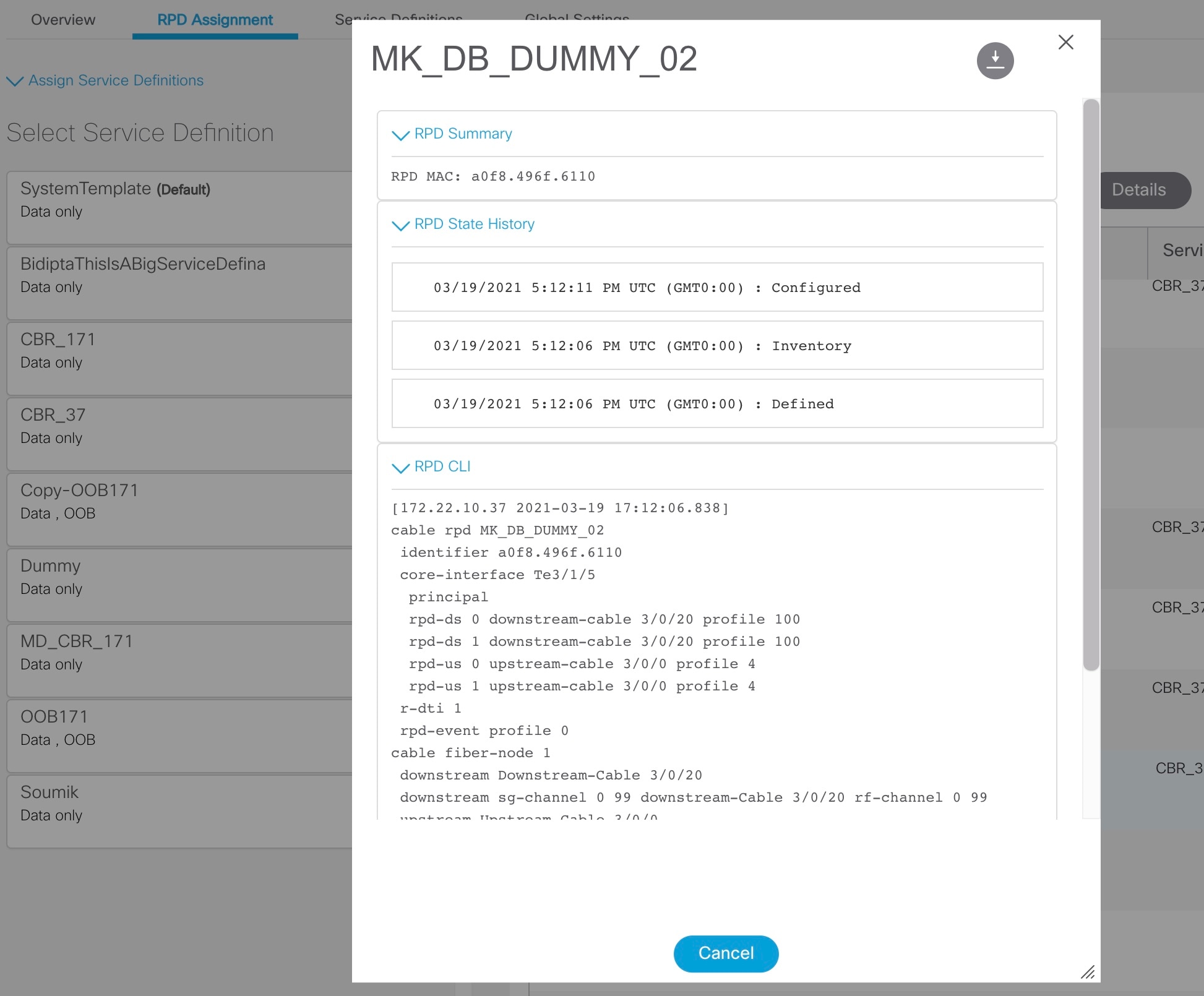
To view the details of an RPD such as the RPD Summary, RPD State History, and RPD CLI, select the checkbox and click the Details button.


Create a New Credential Profile

Before you begin

Make sure that the SSH and SNMP are configured on Cisco cBR-8 router.

Procedure


Step 1

Choose Inventory > Credential Profiles.

Step 2

Click Create New.

Step 3

Enter a profile name and description.

If you have many credential profiles, make the name and description as informative as possible because that information is displayed on the Credential Profiles panel.

Step 4

Enter the credentials for the profile.

When a device is added or updated using this profile, the content you specify here is applied to the device.

Step 5

Click Save.


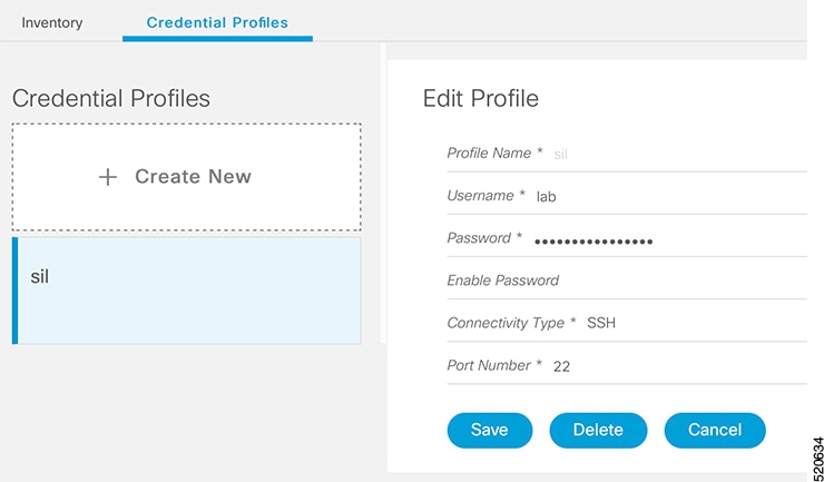
Apply Device Credential from Credential Profiles

Using credential profiles lets you apply credential settings consistently across devices. When you add or import devices, you specify the credential profile the devices use. If you need to make a credential change, such as changing a device password, you can edit the profile to update the settings across all devices that use that profile.

Procedure


Step 1

To view the existing profiles, choose Inventory > Credential Profiles.

Step 2

Click the profile you want to view. Credential profiles can be shared by multiple devices. Large networks might have similar credentials for hundreds of devices.

The mandatory fields are:

  • Profile Name

  • Username

  • Password

  • Connectivity Type

  • Port Number


Apply a Different Credential Profile to Existing Devices

You can use the Inventory user interface to edit device information, including changing the credential profile in the inventory record. This operation overwrites any existing association between a device and a credential profile. You can also use this operation to synchronize device configurations with new settings.

Before you begin

You need a credential profile to complete this task.

Procedure


Step 1

To view inventory, choose Inventory > Inventory.

Step 2

(Optional) In the Inventory section, filter the list of devices by entering text in the Search field or filtering on the individual headings.

Step 3

Check the check boxes of the devices you want to change, and click the Edit icon.

Step 4

Choose a different credential profile from the Credential Profile drop-down list, for example, or make other changes in the device records.

Step 5

Click Save.


Apply Different Credential Profile in Bulk

This is an alternative to changing the credential profile for devices within the Cisco Smart PHY Inventory Manager GUI. If you are changing the credential profile for a large number of devices, you may find it more efficient to make the change by using a CSV file rather than the Cisco Smart PHY UI. Export a CSV file, make the changes, and import the changed CSV file. This operation overwrites any existing association between a device and a credential profile. You can also use this operation to synchronize device configurations with new settings.

Procedure


Step 1

(Optional) To review the contents of a credential profile, choose Inventory > Credential Profiles.

Step 2

Click the profile you want to use. Else, create a new profile.

Step 3

To view device inventory, choose Inventory > Inventory.

Step 4

Choose which device records to change by including them in the CSV file.

Do one of the following:

  • Click the Export icon to include all devices.

  • Filter the list of devices by entering text in the Search field or by filtering on the individual headings, and then click the Export icon to include the filtered list of devices.

  • Check the check boxes for the device records you want to change, and then click the Export icon to include the selected devices.

Step 5

Edit and save the new CSV file. Note: You must save the file opened in MS Excel as a CSV file only.

Step 6

In the Import CSV File dialog box, click Browse, select the new CSV file, and click the Import icon.

Step 7

In the Replace Existing Node dialog box, click Yes to All.

Step 8

Click Save.


Delete a Device from the Inventory

Procedure


Step 1

Choose Inventory > Inventory.

Step 2

(Optional) In the Inventory section, filter the device list by entering text in Search or filtering specific columns.

Step 3

Check the check boxes for the devices you want to delete.

Step 4

Click Delete.

Step 5

In the confirmation dialog box, click Delete.

Deleting an RPD from the Inventory does not delete the corresponding RPD Assignment from the RPD Assignment table. Similarly deleting an RPD Assignment does not delete an RPD from the Inventory.


Create CSV File for Importing Devices

To add information for multiple devices to Inventory Manager, create a CSV file. Inventory Manager contains a sample template CSV file. The GUI for adding individual devices contains field information that also applies to the contents of the CSV files that you create for device import.

Procedure


Step 1

Choose Inventory > Inventory.

Step 2

In the Inventory section, click Import.

You will be prompted to open or save the sample CSV file. Save the CSV file.

Step 3

Edit the CSV file and save it as a CSV file on your system. Upload this CSV file to import devices.

The mandatory fields are:

  • Key Type

  • IP Address

  • Product Type

  • Credential Profile


Export Device Information to a CSV File

When you export the device list to a file, all device information is exported into a CSV file.


Caution

The CSV file lists all the credentials for the exported devices. Handle the CSV file with care. Ensure that only users with special privileges can perform a device export.


Procedure


Step 1

Choose Inventory > Inventory.

Step 2

(Optional) In the Inventory section, filter the device list by entering text in the Search field or filtering specific columns.

Step 3

Check the check boxes for the devices you want to export.

Step 4

Click Export.


Add Devices through GUI

If you have many devices to add to the Inventory Manager, you may find it more efficient to put the information in a CSV file and import the file.

Procedure


Step 1

Choose Inventory > Inventory.

Step 2

In the Inventory section, click Add.

Step 3

Enter the values for the device.

The mandatory fields are:
  • Device Key Type

  • Management IP Address

  • Product Type

  • Credential Profile

Step 4

Click Save.

Step 5

(Optional) Repeat to add more devices.


Import Device Information in Bulk

Before starting this procedure, create a CSV file that contains the device information.

Procedure


Step 1

Choose Inventory > Inventory.

Step 2

Click Import.

Step 3

In the Import CSV File window, click Browse, select the CSV file, and click Import.

If any primary keys are duplicates with existing device records, Inventory Manager alerts you.


Delete a Credential Profile

To delete a credential profile from Inventory Manager, disassociate the profile from any devices. Inventory Manager displays an alert if you attempt to delete a credential profile that is associated with devices.

(Optional) Check whether any devices are using the obsolete credential profile and change the credential profile before deleting the profile..

  1. Choose Inventory > Inventory.

  2. In the Inventory section, enter the obsolete credential profile name in the Search field.

  3. Check the check boxes for the devices that use the obsolete credential profile, and click Edit.

  4. Choose a different credential profile from the Credential Profile drop-down list.

  5. Click Save.

Procedure


Step 1

Choose Inventory > Credential Profiles.

Step 2

Click the profile, and click Delete.


Create a New Service Definition

Procedure


Step 1

Choose Cable RPD Automation > Service Definitions.

Step 2

Click + Create New.

Step 3

Enter a name and description.

If you have many service definitions, make the name and description as informative as possible because that information is displayed on the RPD Assignment and Overview tabs.

Step 4

(Optional) Check the Set as Default check box.

Step 5

Enter the definitions for the Service Definition.

When a device is added or updated using this service definition, the content you specify here is applied to the device. All fields that are not marked as optional are mandatory.

Step 6

Click Save or Save & Assign.


Specify RPD Assignment

Procedure


Step 1

Choose Cable RPD Automation > RPD Assignment.

RPD Assignment can be specified manually or by importing a CSV file.

Step 2

Click + to assign a service template to an RPD.

Fill in all the fields.

To upload a CSV file, click Upload, select the file and click Import.

Step 3

Click Save.

Step 4

Click Assign.


View RPD History

Procedure


Step 1

Choose Cable RPD Automation > RPD Assignment ..

Step 2

Select the RPD and click the Details button.

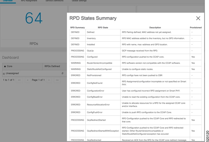
The RPD window shows the RPD Summary, RPD State History, RPD CLI, and RPD Automation Errors.

  1. On the Overview window, click the icon of the RPD State Summary tab to view the details of the RPD States.

Database Backup

The Database Backup section includes the following entry fields:

  • Server

  • Username

  • Password

  • Directory

  • Filename (Used exclusively for the Database Import function.)

The data that you enter in the Server field determines the location of the DB operation.

  • Local backup—localhost

  • Remote operation—IP address or hostname.domain.com

Local Backup

Local backup files are saved to the /var/smartphy/backup directory on the local filesystem.

  1. Go to RPD Automation> Global Settings > Database Backup.

  2. In the Server field enter localhost.

    Leave the remaining fields blank (Username, Password, Directory, and Filename).

  3. Click the Export button.

Remote Backup

Remote backup files are saved to the remote server at the specified file path.

  1. Go to RPD Automation> Global Settings > Database Backup.

  2. In the Server field enter the IP address or the hostname.domain.com of the remote server..

    Enter the user login credentials in the Username and Password fields.

  3. In the Directory field, enter the file path on the remote server.

    Leave the Filename (Import Only) field blank.

  4. Click the Export button.

Add Users and Switching Authentication Plugins

The Cisco Smart PHY application allows local and remote users to access and use the application UI. Through the basic authentication or LDAP authentication process, you can add authorized users to the application. You can also specify the authentication method that you want to use for the Cisco Smart PHY application.

Add Users

Procedure


Step 1

Log in to any one of the control-plane nodes using the following command:

ssh -i <private-key-file> <smartphy-user>@<control-plane-node-ip>
Step 2

Enter the following command.

kubectl get svc ops-center-smartphy-data-ops-center -n smartphy-data

Note the cluster IP address and TCP ports of the service ops-center-smartphy-data-ops-center.

Ops-center-smartphy-data-ops-center    ClusterIP     10.x.x.x    <none>  8008/TCP,8080/TCP,2024/TCP,2022/TCP,7681/TCP        19d
Step 3

Enter the following command to log in to the service resource using the password previously set by the deployer.

ssh admin@<cluster-ip-of-svc> -p <port-number>

Example:

smartphyuser: ~$ ssh admin@10.x.x.x -p 2024
Warning: Permanently added ‘[10.x.x.x]:2024’ (RSA) to the list of known hosts.
admin@10.x.x.x’s password:
Welcome to the smartphy CLI on user/data
admin connected from172.x.x.x using ssh on ops-center-smartphy-data-ops-center-774b8cc6fb-n6qmz
[user/data] smartphy#
Step 4

Run the following command to get into the configuration mode and get a list of available commands.

config
Use the kong command and its sub-commands.
Step 5

Run the following command .

kong user <username> password smartphy
Step 6

Enter the commit command to save the changes and add the new user.

Step 7

Enter end to exit the config mode and enter exit to exit the service resource.


You can log in to the UI using the new username and password. The UI will prompt you to change the password and set a strong password.

Basic and LDAP Authentication

The Cisco Smart PHY application supports the following two different authentication mechanisms:

  • Basic authentication

  • LDAP authentication

The default method is the Basic authentication. You can configure and switch to LDAP and vice versa using the following CLI procedures.

Switch from Basic Authentication to LDAP Authentication


Note

LDAP support is limited to Microsoft Active Directly (AD) only. Open LDAP is not supported.


Procedure


Step 1

Log in to any one of the control-plane nodes using the following command:

ssh -i <private-key-file> <smartphy-user>@<control-plane-node-ip>
Step 2

Enter the following command.

kubectl get svc ops-center-smartphy-data-ops-center -n smartphy-data

Note the cluster IP address and TCP ports of the service ops-center-smartphy-data-ops-center.

Ops-center-smartphy-data-ops-center    ClusterIP     10.x.x.x    <none>
    8008/TCP,8080/TCP,2024/TCP,2022/TCP,7681/TCP        19d
Step 3

Enter the following command to log in to the service resource using the password previously set by the deployer.

ssh admin@<cluster-ip-of-svc> -p <port-number>

Example:

smartphyuser: ~$ ssh admin@10.x.x.x -p 2024
Warning: Permanently added ‘[10.x.x.x]:2024’ (RSA) to the list of known hosts.
admin@10.x.x.x’s password:
Welcome to the smartphy CLI on user/data
admin connected from172.x.x.x using ssh on ops-center-smartphy-data-ops-center-774b8cc6fb-n6qmz
[user/data] smartphy#
Step 4

Run the following command to enter the configuration mode and get a list of available commands.

config
Use the kong command and its sub-commands.
Step 5

Display a list of configuration options available to configure the LDAP authentication plugin using the following command.

kong ldap_plugin configure ?
Step 6

Enter the required details of the Active Directory you want to use with the LDAP authentication plugin and enter commit to save.

Example:

kong ldap_plugin configure attribute cn ldap_host ldap.example.com ldap_port 309 base_dn dc=example,dc=com
Step 7

Enter the following command to enable the LDAP authentication plugin.

kong ldap_plugin enable true
commit
By default, the LDAP plugin is disabled. However, the Basic authentication plugin is enabled.

If you are using the LDAP authentication plugin for the first time, you should configure before enabling it.

Step 8

Enter end to exit the config mode and exit to exit the service resource.


You can log in to the UI using an LDAP user credentials.

Switch from LDAP Authentication to Basic Authentication

Procedure


Step 1

Log in to any one of the control-plane nodes using the following command:

ssh -i <private-key-file> <smartphy-user>@<control-plane-node-ip>
Step 2

Enter the following command.

kubectl get svc ops-center-smartphy-data-ops-center -n smartphy-data

Note the cluster IP address and TCP ports of the service ops-center-smartphy-data-ops-center.

Ops-center-smartphy-data-ops-center    ClusterIP     10.x.x.x    <none>
    8008/TCP,8080/TCP,2024/TCP,2022/TCP,7681/TCP        19d
Step 3

Enter the following command to log in to the service resource using the password previously set by the auto-deployer.

ssh admin@<cluster-ip-of-svc> -p <port-number>

Example:

smartphyuser: ~$ ssh admin@10.x.x.x -p 2024
Warning: Permanently added ‘[10.x.x.x]:2024’ (RSA) to the list of known hosts.
admin@10.x.x.x’s password:
Welcome to the smartphy CLI on user/data
admin connected from172.x.x.x using ssh on ops-center-smartphy-data-ops-center-774b8cc6fb-n6qmz
[user/data] smartphy#
Step 4

Run the following command to enter the configuration mode and get a list of available commands.

config
Use the kong command and its sub-commands.
Step 5

Enable the Basic authentication plugin regardless of the status of LDAP authentication plugin.

kong ldap_plugin enable false
Step 6

Enter the commit command to save the changes and start using the Basic authentication plugin.

Step 7

Enter end to exit the config mode and enter exit to exit the service resource.


Basic authentication plugin is enabled and you can log in to the UI using a local existing username and password.