Installing the Cisco CMC
Available Languages
Contents
- Installing the Cisco CMC
- Mounting the Cisco CMC
- Wall-Mounting the Cisco CMC
- Strand-Mounting the Cisco CMC
- Opening the Cisco CMC
- Removing and Installing the Accessories on the Cisco CMC
- Installing the Coaxial Cables on the Cisco CMC
- Trimming the Center Conductor on the F-Connector
- Connecting the Coaxial Cable to the Cisco CMC
- Installing a Fiber Adapter on the Cisco CMC
- Installing an SFP Module on the Cisco CMC
- Connecting the Optical Fibers to the SFP Module
- Connecting the RJ-45 Cables to the Cisco CMC
- Connecting the Optical Fibers to the FRx
- Connecting I/O to the Cisco CMC
- Enabling the 4-Way Forward Output RF Configuration on the Cisco CMC
- Enabling the 2-Way Forward Output RF Configuration on the Cisco CMC
- Enabling the 4-Way Reverse Input RF Configuration on the Cisco CMC
- Enabling the 2-Way Reverse Input RF Configuration on the Cisco CMC
- Powering Up the Cisco CMC
- Grounding the Cisco CMC
- Powering Up the Cisco CMC with the 220VAC PSU
- Powering Up the Cisco CMC with the 60VAC PSU
- Connecting 60VAC Power to the Cisco CMC Through the Power Port
- Connecting 60VAC Power to the Cisco CMC Through the RF Port
- Closing the Cisco CMC
Installing the Cisco CMC
This section provides information on how to install the Cisco CMC.
Mounting the Cisco CMC
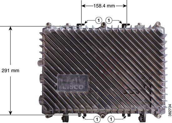
Wall-Mounting the Cisco CMC
Before You BeginProcedure
- To prevent injury and damage to the equipment, review the safety guidelines in Preparing for the Cisco Remote-PHY Solution Installation before installing the Cisco CMC on the wall.
- Close the Cisco CMC lid. See Closing the Cisco CMC.
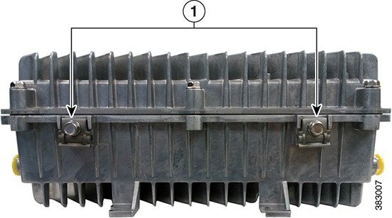
Strand-Mounting the Cisco CMC
Before You BeginProcedure
- To prevent injury and damage to the equipment, review the safety guidelines in Preparing for the Cisco Remote-PHY Solution Installation before installing the Cisco CMC on the strand.
- Close the Cisco CMC lid. See Closing the Cisco CMC.
- Have the following tools ready before performing this task:
Step 1 Check the strand size. The minimum strand diameter must be 5/16". Step 2 Loosen the strand clamp bolts on the Cisco CMC to separate the clamps enough to insert the strand, but do not remove them. Step 3 Place the Cisco CMC into proper position on the strand. Step 4 Insert the clamps over the strand and tighten the strand clamp bolts with your fingers. This allows additional side-to-side movement of the Cisco CMC as needed. Step 5 Move and position the Cisco CMC on the strand as required for installing the cables. Step 6 Tighten the strand clamp bolts from 5 ft-lb to 8 ft-lbs (6.8 to 10.8 Nm) using a torque wrench and 1/2-inch socket .
Note Due to the strand tension, a slight tilt of the face of the Cisco CMC is normal.
Opening the Cisco CMC
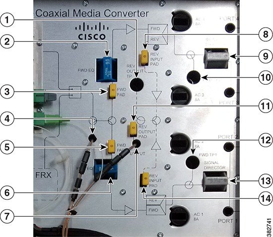
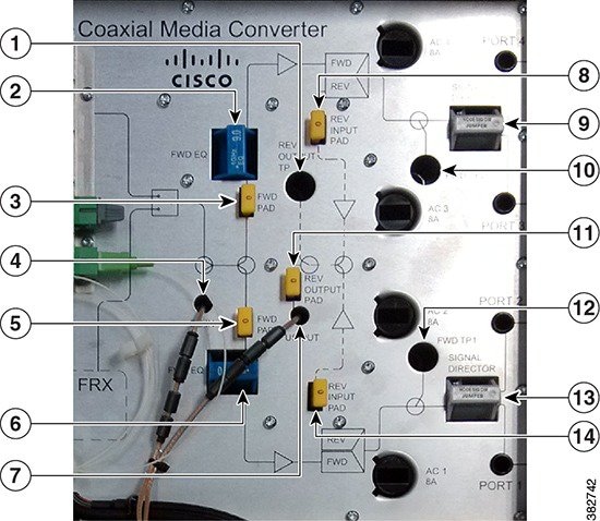
Removing and Installing the Accessories on the Cisco CMC
This section provides information on how to remove and install the following accessories located inside the Cisco CMC.
Accessory
Description
Illustration
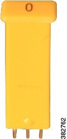
Attenuator pads
An attenuator pad produces flat (even) loss across the forward and reverse frequency spectrums. It is used during the station balancing to adjust signal levels. The loss (in dB) produced by an attenuator pad is equal to the value printed on the top of the attenuator pad. An attenuator pad with 75 Ω printed on the top works as a 75 ohm terminator.
Important:Do not change the attenuator pads, unless specified by the system design.
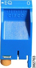
Equalizers
An equalizer produces linear tilt. It must be used on the Cisco CMC if the output tilt does not have the desired output tilt. The EQ value specified on the equalizer is the amount of tilt from lowest to highest frequency (52 to 1002 MHz).
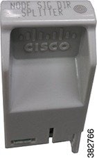
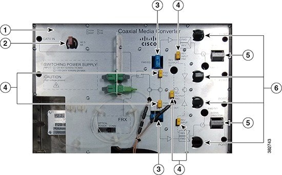
Signal director—Splitter
A splitter splits the RF input signal to feed two RF output ports. It is used for configuring the 4-way RF configuration on the Cisco CMC.
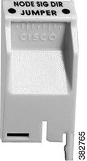
Signal director—Jumper
A jumper routes the RF input signal to the RF output port. It is used for configuring the 2-way RF configuration on the Cisco CMC.
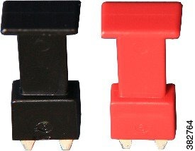
AC shunts
An AC shunt is used for configuring the power direction in the Cisco CMC with the 60VAC power supply unit. Use the red AC shunt for the RF input port and black AC shunts for the RF output ports.
Warning Remove all the AC shunts if they are installed in the Cisco CMC before connecting the coaxial cables to the F-connectors.
Note Do not use AC shunts in the Cisco CMC with the 220VAC power supply unit.
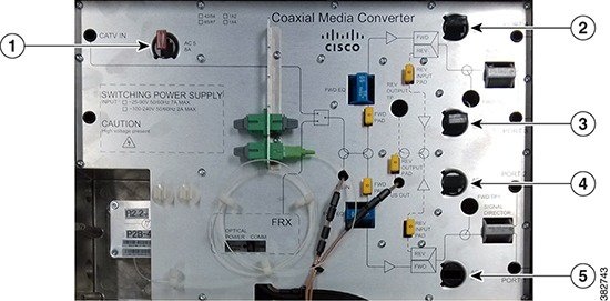
These accessories can be removed and installed in the Cisco CMC through the cutouts in the base cover.
Before You BeginProcedureOpen the Cisco CMC lid. See Opening the Cisco CMC.
What to Do Next
Close the Cisco CMC lid. See Closing the Cisco CMC.
Installing the Coaxial Cables on the Cisco CMC
Coaxial cables carry the forward-path RF signal input and outputs, and reverse-path RF signal inputs on the Cisco CMC. The coaxial cables can also supply 25 to 90VAC power input to the Cisco CMC. You can install up to:
Trimming the Center Conductor on the F-Connector
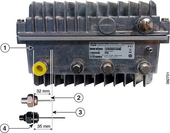
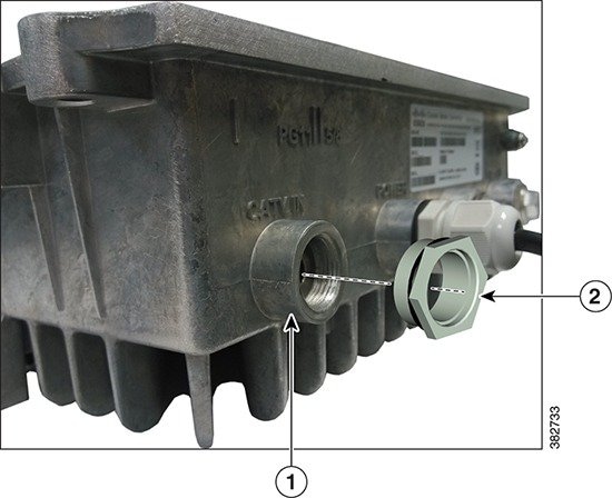
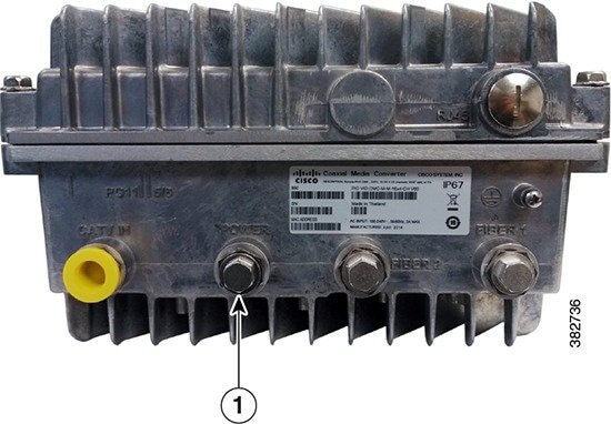
ProcedureF-connectors are used for the RF connections on the Cisco CMC. The Cisco CMC supports PG11 and 5/8" F-connectors. The Cisco CMC has a strip on the external housing that shows the center conductor pin trim length for the F-connector. You must trim the center conductor pin if it extends beyond the strip line on the Cisco CMC before inserting it into the RF ports.
Step 1 Place the F-connector above the CATV IN port on the Cisco CMC so that the seal shoulder aligns with the strip. Step 2 Perform one of the following:
- For the 5/8" F-connector, if the center conductor pin extends beyond the 5/8”-strip line, trim the pin to the 5/8”-strip line (35 mm) using a heavy-duty wire cutter.
- For the PG11 F-connector, if the center conductor pin extends beyond the PG11-strip line, trim the pin to the PG11-strip line (32 mm) using a heavy-duty wire cutter.
The figure below shows a visual guide of the center conductor trim length.
Step 3 Remove any burrs or sharp edges on the trimmed end of the center conductor pin using a deburring tool.
Connecting the Coaxial Cable to the Cisco CMC
Before You BeginProcedure
- Open the Cisco CMC lid. See Opening the Cisco CMC.
- Remove the plastic cover or 5/8" port plug from the RF ports on the Cisco CMC using a torque wrench.
- Have the following tools ready before performing this task:
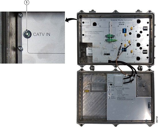
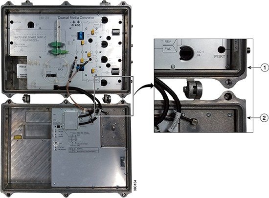
Step 1 Trim the center conductor pin with a heavy-duty wire cutter if it extends beyond the strip line on the Cisco CMC. See Trimming the Center Conductor on the F-Connector. Step 2 Lightly loosen the seizure screw, do not remove it. The figure below shows the location of the seizure screw inside the Cisco CMC. Step 3 To use the PG11 F-connector, remove the PG11-to-5/8" adapter plug from the RF port using a torque wrench. The figure below shows the PG11-to-5/8" adapter plug. Step 4 Insert the F-connector into the RF port. Tighten the connector nut with a torque wrench. Step 5 Tighten the seizure screw from 2 ft-lb to 5 ft-lb (2.7 Nm to 6.8 Nm) using a slot screwdriver. Step 6 Remove the AC shunt for the RF port to prevent damage to the equipment that is connected to the other end of the coaxial cable. Step 7 Connect the coaxial cable to the F-connector. Step 8 Reinstall the AC shunt for the RF port. Step 9 Repeat Step 1 through Step 7 for each RF port used. Step 10 Check if RF signal is present at the unused RF ports and perform one of the following:
What to Do Next
Close the Cisco CMC lid. See Closing the Cisco CMC.
Installing a Fiber Adapter on the Cisco CMC
The Cisco CMC supports two types of fiber adapters:
The Cisco CMC contains two pre-installed SC/APC-SC/APC fiber adapters. Perform this procedure to install additional fiber adapters.
Before You BeginProcedureOpen the Cisco CMC lid. See Opening the Cisco CMC.
Step 1 Align the fiber adapter with the slot. Step 2 Insert the fiber adapter through the slot as shown in the figure below until you feel the fiber adapter lock into the slot. Step 3 Remove the dust plug from the fiber adapter and connect the optical fibers. See Connecting the Optical Fibers to the SFP Module and Connecting the Optical Fibers to the FRx.
What to Do Next
Close the Cisco CMC lid. See Closing the Cisco CMC.
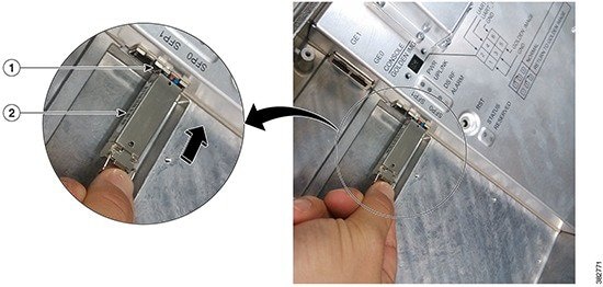
Installing an SFP Module on the Cisco CMC
Before You BeginProcedureOpen the Cisco CMC lid. See Opening the Cisco CMC.
Step 1 Remove the SFP module from its protective packaging. Step 2 Locate the transmit (Tx) and receive (Rx) markings on the top side of the SFP module.
Note On some SFP modules, the Tx and Rx markings may be replaced by arrowheads pointing from the SFP connector (transmit direction or Tx) and towards the connector (receive direction or Rx).
Step 3 Align the SFP module with the socket opening. Step 4 Insert the SFP module into the socket until you feel the SFP module connector lock into the socket connector and then close the SFP latch. Step 5 Remove the dust plug from the SFP module and save it for future use.
Note For optical SFP module, before you remove the dust plugs and make any optical connections, observe these guidelines:
Step 6 Perform one of the following:
- For the optical SFP module, connect the optical fibers to the SFP module. See Connecting the Optical Fibers to the SFP Module.
- For the Gigabit Ethernet SFP module, connect the RJ-45 cable to the Gigabit Ethernet SFP module. See Connecting the RJ-45 Cables to the Cisco CMC.
What to Do Next
Close the Cisco CMC lid. See Closing the Cisco CMC.
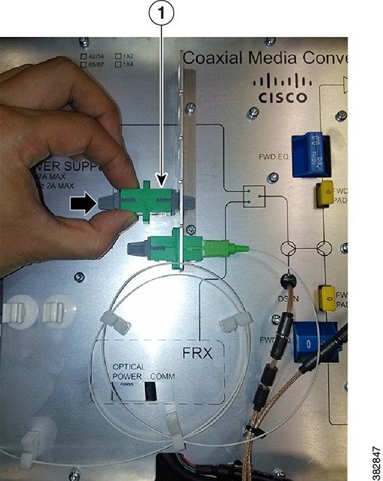
Connecting the Optical Fibers to the SFP Module
Before You BeginProcedure
- Open the Cisco CMC lid. See Opening the Cisco CMC.
- Install the SFP module on the Cisco CMC. See Installing an SFP Module on the Cisco CMC.
- Remove the 5/8" port plug from the fiber port on the Cisco CMC using a torque wrench
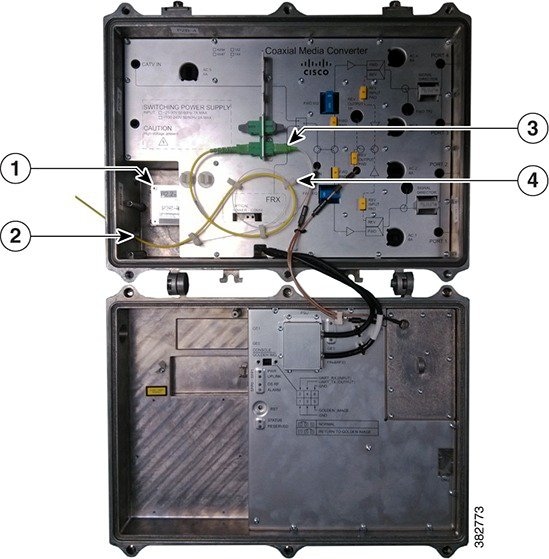
Step 1 Insert the optical fiber into the fiber port. Step 2 Secure the optical fibers using the cable clips and insert the optical fiber connector into the SFP port until it clicks and locks into place and as shown in the figure below: Step 3 Seal the fiber port with an appropriate gland to waterproof the port.
What to Do Next
Close the Cisco CMC lid. See Closing the Cisco CMC.
Connecting the RJ-45 Cables to the Cisco CMC
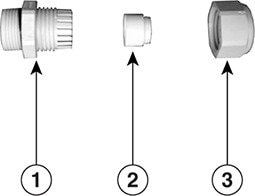
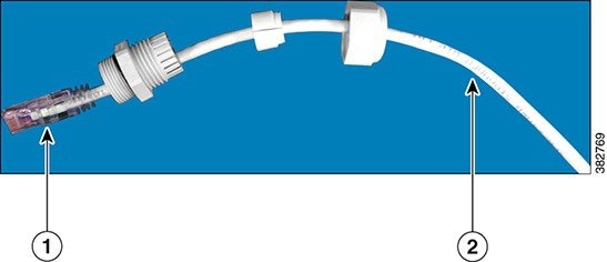
Use the PG16 gland to connect the RJ-45 cable to the Cisco CMC.
The Cisco CMC supports two types of PG16 glands for the RJ-45 port:
Before You BeginProcedure
- Open the Cisco CMC lid. See Opening the Cisco CMC.
- Have the following tools ready before performing this task:
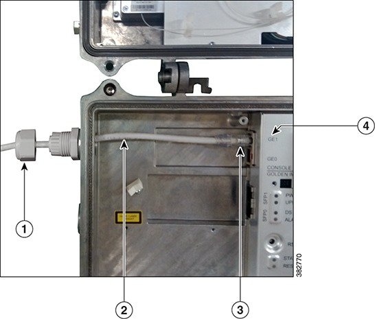
Step 1 Remove the PG16 port plug or the PG16 gland from the RJ-45 port on the Cisco CMC if it is already installed. Step 2 Insert the RJ-45 cable through the PG16 gland as shown in the figure below. Step 3 Insert the RJ-45 connector through the RJ-45 port on the Cisco CMC. Step 4 Insert the RJ-45 connector into the Gigabit Ethernet port until it clicks and locks into place. Step 5 Tighten the PG16 gland into the RJ-45 port using a torque wrench (4.44 ft-lb) and then tighten the dome cap using a torque wrench (2.44 ft-lb).
What to Do Next
Close the Cisco CMC lid. See Closing the Cisco CMC.
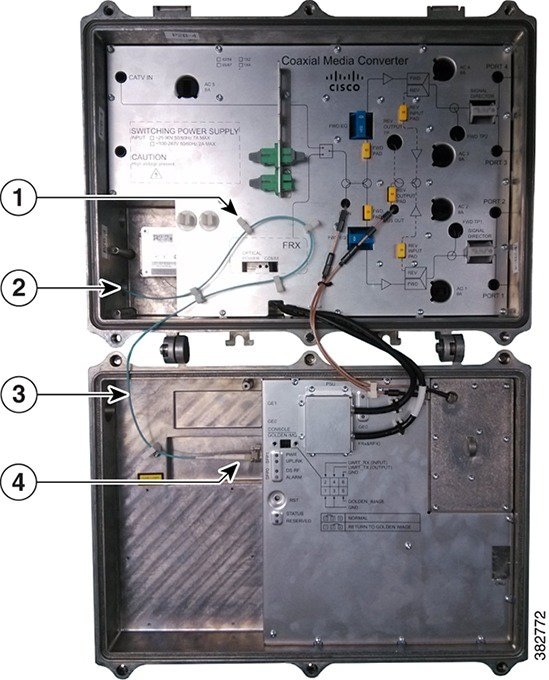
Connecting the Optical Fibers to the FRx
Before You BeginProcedure
- Open the Cisco CMC lid. See Opening the Cisco CMC.
- Ensure that the Forward Optical Receiver Module (FRx) module is installed on the Cisco CMC. To install the FRx on the Cisco CMC, contact the Cisco Technical Assistance Center (TAC) for further assistance.
- Remove the 5/8" port plug from the fiber port on the Cisco CMC using a torque wrench.
What to Do Next
Close the Cisco CMC lid. See Closing the Cisco CMC.
Connecting I/O to the Cisco CMC
The Cisco CMC supports two types of I/O configurations:
Forward-Path I/O Configurations
Forward-path refers to the signals received at the Cisco CMC from the headend. These signals are amplified in the Cisco CMC and routed to the subscribers through the cable modems. The Cisco CMC supports the following forward-path RF configurations:
Reverse-Path I/O Configurations
Reverse-path refers to the signals received at the Cisco CMC from the cable modem. These signals are amplified in Cisco CMC and returned to the headend optically through the fiber portion of the network. The reverse-path RF configuration is not used in all networks. The Cisco CMC supports the following reverse-path RF configurations:
Enabling the 4-Way Forward Output RF Configuration on the Cisco CMC
Before You BeginProcedureOpen the Cisco CMC lid. See Opening the Cisco CMC.
Step 1 Remove all the AC shunts installed on the Cisco CMC. Removing the AC shunts prevents damage to the equipment that is connected on the other end of the coaxial cable. Power surge to the components and F-connectors is reduced when the AC shunts are removed.
Caution The RF connectors and housing seizure assemblies can get damaged if the AC shunts are not removed from the Cisco CMC before installing or removing the components from the housing.
Step 2 Insert the signal director—splitter to provide the RF output to the four RF output ports. Step 3 Perform one of the following:
- If FRx is installed on the Cisco CMC, connect the optical input signal to the FRx. See Connecting the Optical Fibers to the FRx.
- If FRx is not installed on the Cisco CMC, insert the F-connector into the CATV IN port. Connect the coaxial cable from the node or amplifier in the HFC network to the F-connector. See Installing the Coaxial Cables on the Cisco CMC.
Step 4 Insert the F-connector into each RF output port (Port 1 through Port 4). Connect the coaxial cable from each F-connector to the cable modem. See Installing the Coaxial Cables on the Cisco CMC. Step 5 Reinstall the AC shunts on the Cisco CMC.
What to Do Next
Close the Cisco CMC lid. See Closing the Cisco CMC.
Enabling the 2-Way Forward Output RF Configuration on the Cisco CMC
Before You BeginProcedureOpen the Cisco CMC lid. See Opening the Cisco CMC.
Step 1 Remove all the AC shunts installed on the Cisco CMC. Removing the AC shunts prevents damage to the equipment that is connected on the other end of the coaxial cable. Power surge to the components and F-connectors is reduced when the AC shunts are removed.
Caution The RF connectors and housing seizure assemblies can get damaged if the AC shunts are not removed from the Cisco CMC before installing or removing the components from the housing.
Step 2 Insert the signal director—jumper to provide the RF output to two RF output ports. Step 3 Perform one of the following:
- If FRx is installed on the Cisco CMC, connect the optical input signal to the FRx. See Connecting the Optical Fibers to the FRx.
- If FRx is not installed on the Cisco CMC, insert the F-connector into the CATV IN port. Connect the coaxial cable from the node or amplifier in the HFC network to the F-connector. See Installing the Coaxial Cables on the Cisco CMC.
Step 4 Insert the F-connector into two RF output ports. Connect the coaxial cable from each F-connector to the cable modem. See Installing the Coaxial Cables on the Cisco CMC.
Note We recommend that you provide the RF output through the Port 1 and Port 4 for the 2-way forward output RF configuration.
Step 5 Reinstall the AC shunts on the Cisco CMC.
What to Do Next
Close the Cisco CMC lid. See Closing the Cisco CMC.
Enabling the 4-Way Reverse Input RF Configuration on the Cisco CMC
Before You BeginProcedureOpen the Cisco CMC lid. See Opening the Cisco CMC.
Step 1 Remove all the AC shunts installed on the Cisco CMC. Removing the AC shunts prevents damage to the equipment that is connected on the other end of the coaxial cable. Power surge to the components and F-connectors is reduced when the AC shunts are removed.
Caution The RF connectors and housing seizure assemblies can get damaged if the AC shunts are not removed from the Cisco CMC before installing or removing the components from the housing.
Step 2 Insert the signal director—splitter to provide the RF input from the four RF output ports. Step 3 Insert the F-connector into each RF output port (Port 1 through Port 4). Connect the coaxial cables from the cable modems to each F-connectors. See Installing the Coaxial Cables on the Cisco CMC. Step 4 Reinstall the AC shunts on the Cisco CMC. Step 5 Perform one of the following:
- If the optical SFP module is installed on the Cisco CMC, connect the optical fiber from the SFP module to the digital fiber network. See Connecting the Optical Fibers to the SFP Module.
- If the optical SFP module is not installed on the Cisco CMC, connect the RJ-45 cable from the Gigabit Ethernet port to the PON module in the digital fiber network. See Connecting the RJ-45 Cables to the Cisco CMC.
What to Do Next
Close the Cisco CMC lid. See Closing the Cisco CMC.
Enabling the 2-Way Reverse Input RF Configuration on the Cisco CMC
Before You BeginProcedureOpen the Cisco CMC lid. See Opening the Cisco CMC.
Step 1 Remove all the AC shunts installed on the Cisco CMC. Removing the AC shunts prevents damage to the equipment that is connected on the other end of the coaxial cable. Power surge to the components and F-connectors is reduced when the AC shunts are removed.
Caution The RF connectors and housing seizure assemblies can get damaged if the AC shunts are not removed from the Cisco CMC before installing or removing the components from the housing.
Step 2 Insert the signal director—jumper to provide the RF input from the two RF output ports. Step 3 Insert the F-connector into two RF output ports. Connect the coaxial cable from the cable modems to each F-connector. See Installing the Coaxial Cables on the Cisco CMC.
Note We recommend that you provide the RF input through the Port 1 and Port 4 for the 2-way reverse input RF configuration.
Step 4 Reinstall the AC shunts on the Cisco CMC. Step 5 Perform one of the following:
- If the optical SFP module is installed on the Cisco CMC, connect the optical fiber from the SFP module to the digital fiber network. See Connecting the Optical Fibers to the SFP Module.
- If the optical SFP module is not installed on the Cisco CMC, connect the RJ-45 cable from the Gigabit Ethernet port to the PON module in the digital fiber network. See Connecting the RJ-45 Cables to the Cisco CMC.
What to Do Next
Close the Cisco CMC lid. See Closing the Cisco CMC.
Powering Up the Cisco CMC
Warning
Before working on equipment that is connected to power lines, remove jewelry (including rings, necklaces, and watches). Metal objects will heat up when connected to power and ground and can cause serious burns or weld the metal object to the terminals. Statement 43.
Warning
This equipment must be grounded. Never defeat the ground conductor or operate the equipment in the absence of a suitably installed ground conductor. Contact the appropriate electrical inspection authority or an electrician if you are uncertain that suitable grounding is available. Statement 1024
Warning
This unit might have more than one power supply connection. All connections need to be removed to de-energize the unit. Statement 1028
Before powering up the Cisco CMC, you must provide an adequate ground connection for the equipment.
The Cisco CMC available in the following variants of the power supply unit (PSU):
The following sections provide information on how to ground and power up the Cisco CMC:
Grounding the Cisco CMC
ProcedureGrounding the equipment is mandatory for the Cisco CMC with the 60VAC PSU and optional for the Cisco CMC with the 220VAC PSU.
Warning
Use copper conductors only. Statement 1025.
Warning
This equipment must be grounded. Never defeat the ground conductor or operate the equipment in the absence of a suitably installed ground conductor. Contact the appropriate electrical inspection authority or an electrician if you are uncertain that suitable grounding is available. Statement 1024.
Warning
When installing or replacing the unit, the ground connection must always be made first and disconnected last. Statement 1046.
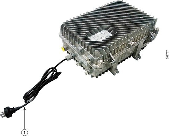
Powering Up the Cisco CMC with the 220VAC PSU
Before You BeginProcedureOpen the Cisco CMC lid. See Opening the Cisco CMC.
What to Do Next
Verify if the PWR LED illuminates (green) to ensure that the Cisco CMC is powered up. Close the Cisco CMC lid. See Closing the Cisco CMC.
Powering Up the Cisco CMC with the 60VAC PSU
This section describes how to power up the Cisco CMC with the 60VAC PSU:
Connecting 60VAC Power to the Cisco CMC Through the Power Port
Before You BeginProcedure
- Ensure that the grounding wire is installed before powering up the Cisco CMC. See Grounding the Cisco CMC.
- The F-connector used for connecting the 60VAC power must meet the following requirements:
- Open the Cisco CMC lid. See Opening the Cisco CMC.
Restrictions
Warning
You must supply 60VAC power to the Cisco CMC with 60VAC PSU using only one coaxial cable. Connecting more than one coaxial cable with the 60VAC power damages the Cisco CMC. If you are connecting a modem to the port that has a black AC shunt, ensure to use combiners in the network to isolate pass-through power to prevent accidental injury.
Step 1 Ensure that the power source is switched off. Step 2 Install the F-connector in the power port. See Connecting the Coaxial Cable to the Cisco CMC. Step 3 Connect the coaxial cable to the F-connector. Step 4 Connect the other end of the coaxial cable to a 60VAC power source. Step 5 Switch on the power source to power up the Cisco CMC.
What to Do Next
Verify if the PWR LED illuminates (green) to ensure that the Cisco CMC is powered up. Close the Cisco CMC lid. See Closing the Cisco CMC.
Connecting 60VAC Power to the Cisco CMC Through the RF Port
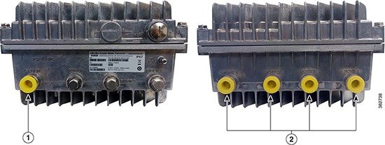
For the Cisco CMC with the 60VAC PSU, the power direction is configured by installing the AC shunts for the RF ports through which the AC power is passed. Use the red AC shunt for the RF input port and black AC shunts for the RF output ports.
Before You BeginProcedure
- Ensure that the grounding wire is installed before powering up the Cisco CMC. See Grounding the Cisco CMC.
- The F-connector used for connecting the 60VAC power must meet the following requirements:
- Open the Cisco CMC lid. See Opening the Cisco CMC.
Restrictions
Warning
You must supply 60VAC power to the Cisco CMC with 60VAC PSU using only one coaxial cable. Connecting more than one coaxial cable with the 60VAC power damages the Cisco CMC. If you are connecting a modem to the port that has a black AC shunt, ensure to use combiners in the network to isolate pass-through power to prevent accidental injury.
Step 1 Ensure that the power source is switched off. Step 2 Install the F-connector in the CATV IN and four RF output ports (Port 1 through Port 4). See Connecting the Coaxial Cable to the Cisco CMC.
Note Each RF port can support up to 8 A. Ensure that the total current from all the four RF output ports and Cisco CMC does not exceed 8 A.
Step 3 Remove all the AC shunts installed on the Cisco CMC. Step 4 Connect the coaxial cables to the F-connectors. Step 5 Insert the black AC shunts for the RF ports that need to be supplied with 60VAC power from the Cisco CMC. Step 6 Insert the red AC shunt for the RF port that supplies 60VAC power to the Cisco CMC. Connect the other end of the coaxial cable to a 60VAC power source. Step 7 Switch on the power source to power up the Cisco CMC.
What to Do Next
Verify if the PWR LED illuminates (green) to ensure that the Cisco CMC is powered up. Close the Cisco CMC lid. See Closing the Cisco CMC.
Closing the Cisco CMC
Proper housing closure is important to maintain the Cisco CMC in good working condition. Proper closure ensures a good seal against the environment and protects the internal modules.
Caution
Avoid moisture damage and RF leakage. Follow the procedure exactly as shown below to ensure a proper seal.
The Cisco CMC has waterproof rubber and EMI gasket to seal the equipment.
Before You BeginProcedure
- Ensure that the waterproof rubber and EMI gasket on the Cisco CMC are not worn out. Wipe off any excess dirt and debris. If the waterproof rubber or EMI gasket is worn out, contact the Cisco Technical Assistance Center (TAC) for further assistance.
- Have the following tools ready before performing this task:
Step 1 Close the lid.
Caution Ensure that all the cables are out of the way when closing the lid.
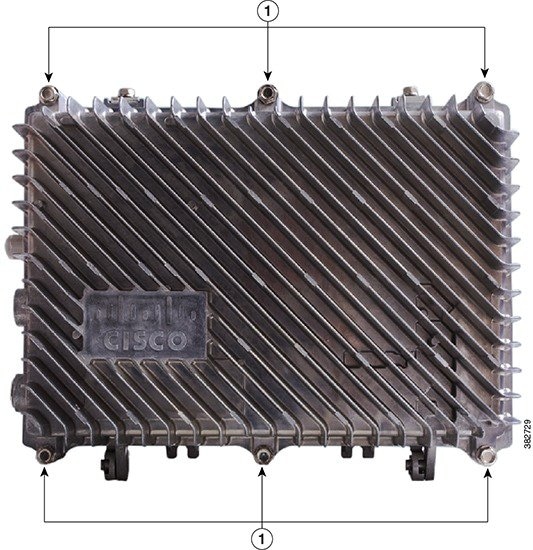
Step 2 Lightly secure the six 1/2-inch closure bolts using a hex driver or ratchet. Step 3 Tighten the six housing closure bolts from 5 ft-lb to 12 ft-lb (6.8 Nm to 16.3 Nm) using a torque wrench in the correct sequence as shown in the figure below. Step 4 Using the same sequence, tighten the closure bolts again with the same torque specification to ensure proper closure.
Notices
Copyright © 2014, Cisco Systems, Inc. All rights reserved.


 Feedback