Cisco Wide Area Virtualization Engine 294 Hardware Installation Guide
Bias-Free Language
The documentation set for this product strives to use bias-free language. For the purposes of this documentation set, bias-free is defined as language that does not imply discrimination based on age, disability, gender, racial identity, ethnic identity, sexual orientation, socioeconomic status, and intersectionality. Exceptions may be present in the documentation due to language that is hardcoded in the user interfaces of the product software, language used based on RFP documentation, or language that is used by a referenced third-party product. Learn more about how Cisco is using Inclusive Language.
- Updated:
- March 18, 2015
Chapter: Installing the WAVE-294
Installing the WAVE-294
This chapter describes how to install a WAVE-294 in an equipment rack. This chapter contains the following sections:
•![]() Rack-Mounting Considerations, Parts, and Tools
Rack-Mounting Considerations, Parts, and Tools
•![]() Rack Mounting and Cabling the WAVE-294
Rack Mounting and Cabling the WAVE-294
•![]() Connecting Power and Booting the System
Connecting Power and Booting the System
•![]() Removing or Replacing a WAVE Appliance
Removing or Replacing a WAVE Appliance
Before you begin the installation, read Chapter 2 "Preparing to Install the WAVE-294" and the Regulatory Compliance and Safety Information for Cisco Wide Area Virtualization Engines document.
 |
Warning |
Rack-Mounting Considerations, Parts, and Tools
To allow for servicing and adequate airflow, observe the following space and airflow requirements when deciding where to install a rack:
•![]() Leave a minimum clearance of 63.5 cm (25 in) in front of the rack.
Leave a minimum clearance of 63.5 cm (25 in) in front of the rack.
•![]() Leave a minimum clearance of 76.2 cm (30 in) behind the rack.
Leave a minimum clearance of 76.2 cm (30 in) behind the rack.
•![]() Leave a minimum clearance of 121.9 cm (48 in) from the back of the rack to the back of another rack or row of racks.
Leave a minimum clearance of 121.9 cm (48 in) from the back of the rack to the back of another rack or row of racks.
The WAVE-294 appliance draws in cool air through the front door and expels warm air through the rear door. Therefore, the front and rear rack doors must be adequately ventilated to allow ambient room air to enter the cabinet, and the rear door must be adequately ventilated to allow the warm air to escape from the cabinet.
 |
Caution |
When vertical space in the rack is not filled by a WAVE appliance or rack component, the gaps between the components cause changes in airflow through the rack and across the WAVE appliances. Cover all gaps with filler panels to maintain proper airflow.
|
Caution |
•![]() Observe the following additional requirements to ensure adequate airflow and to prevent damage to the equipment:
Observe the following additional requirements to ensure adequate airflow and to prevent damage to the equipment:
–![]() Front and rear doors—If the 42U rack includes closing front and rear doors, you must allow 5,350 sq cm (830 sq in) of holes evenly distributed from top to bottom to permit adequate airflow (equivalent to the required 64 percent open area for ventilation).
Front and rear doors—If the 42U rack includes closing front and rear doors, you must allow 5,350 sq cm (830 sq in) of holes evenly distributed from top to bottom to permit adequate airflow (equivalent to the required 64 percent open area for ventilation).
–![]() Side—The clearance between the installed rack component and the side panels of the rack must be a minimum of 7 cm (2.75 in).
Side—The clearance between the installed rack component and the side panels of the rack must be a minimum of 7 cm (2.75 in).
 |
Note |
Table 3-1 lists the rack mounting hardware included in your shipping container. You will need a Phillips screwdriver. Verify that you have received the following items for the installation:
Rack Mounting and Cabling the WAVE-294
There are two ways you can rack mount the WAVE appliance. The following topics are included in this section:
•![]() Front-Mounting in a 2-Post Rack
Front-Mounting in a 2-Post Rack
Mounting in a 4-Post Rack
Follow these steps to mount the WAVE appliance in a 4-post rack:
Step 1 ![]() Prepare for installation by reading the "Rack-Mounting Considerations, Parts, and Tools" section) and verify that you have the correct tools and rack-mount hardware necessary for the installation.
Prepare for installation by reading the "Rack-Mounting Considerations, Parts, and Tools" section) and verify that you have the correct tools and rack-mount hardware necessary for the installation.
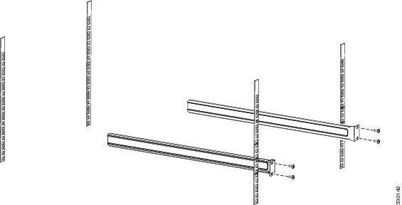
Step 2 ![]() Attach the front rack mount brackets (item #1 in Table 3-1) using the six front bracket screws (item #4 in Table 3-1). (See Figure 3-4.)
Attach the front rack mount brackets (item #1 in Table 3-1) using the six front bracket screws (item #4 in Table 3-1). (See Figure 3-4.)
Step 3 ![]() Attach the rear rack mount holder brackets (item #2 in Table 3-1) using the six rear bracket holder screws (item #5 in Table 3-1).
Attach the rear rack mount holder brackets (item #2 in Table 3-1) using the six rear bracket holder screws (item #5 in Table 3-1).
|
Note |
Figure 3-1 Attaching the Brackets

Step 4 ![]() Attach the rear mount bracket holders (item #3 in Table 3-1) to the rear rack posts using four appropriate rack screws (item #6 or #7 in Table 3-1). (see Figure 3-2)
Attach the rear mount bracket holders (item #3 in Table 3-1) to the rear rack posts using four appropriate rack screws (item #6 or #7 in Table 3-1). (see Figure 3-2)
Figure 3-2 Attaching Rear Rack Mount to the Rack
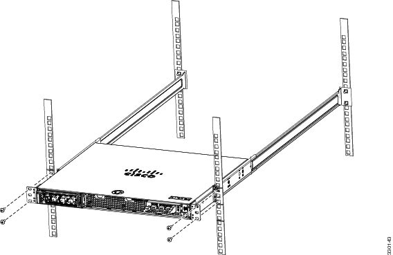
Step 5 ![]() Insert the chassis between the mounting posts and secure (see Figure 3-3):
Insert the chassis between the mounting posts and secure (see Figure 3-3):
a. ![]() Insert the chassis into the rack with the rear rack mount holders sliding into the rear rack mount brackets.
Insert the chassis into the rack with the rear rack mount holders sliding into the rear rack mount brackets.
b. ![]() Align the mounting holes in the front brackets with the mounting holes in the equipment rack.
Align the mounting holes in the front brackets with the mounting holes in the equipment rack.
c. ![]() Secure the chassis using four (two on each side) rack screws (item #6 or #7 in Table 3-1) through the holes in the front brackets and into the threaded holes in the mounting post.
Secure the chassis using four (two on each side) rack screws (item #6 or #7 in Table 3-1) through the holes in the front brackets and into the threaded holes in the mounting post.
Figure 3-3 Rack-Mounting the Chassis
Step 6 ![]() Verify that the chassis is securely installed in the rack.
Verify that the chassis is securely installed in the rack.
Front-Mounting in a 2-Post Rack
Follow these steps to front-mount the WAVE appliance in a 2-post rack:
|
Note |
Step 1 ![]() Prepare for installation by reading the "Rack-Mounting Considerations, Parts, and Tools" section) and verify that you have the correct tools and rack-mount hardware necessary for the installation.
Prepare for installation by reading the "Rack-Mounting Considerations, Parts, and Tools" section) and verify that you have the correct tools and rack-mount hardware necessary for the installation.
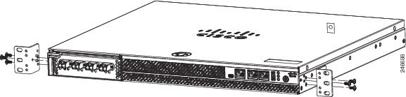
Step 2 ![]() Attach the front rack mount brackets (item #1 in Table 3-1) using the six front bracket screws (item #4 in Table 3-1). (See Figure 3-4.)
Attach the front rack mount brackets (item #1 in Table 3-1) using the six front bracket screws (item #4 in Table 3-1). (See Figure 3-4.)
Figure 3-4 Attaching the Front Brackets
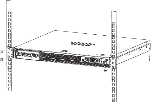
Step 3 ![]() Insert the chassis between the mounting posts and secure (see Figure 3-5):
Insert the chassis between the mounting posts and secure (see Figure 3-5):
a. ![]() Align the mounting holes in the front brackets with the mounting holes in the equipment rack.
Align the mounting holes in the front brackets with the mounting holes in the equipment rack.
b. ![]() Secure the chassis using four (two on each side) rack screws (item #6 or #7 in Table 3-1) through the holes in the front brackets and into the threaded holes in the mounting post.
Secure the chassis using four (two on each side) rack screws (item #6 or #7 in Table 3-1) through the holes in the front brackets and into the threaded holes in the mounting post.
c. ![]() Use a tape measure and level to ensure that the chassis is installed straight and level.
Use a tape measure and level to ensure that the chassis is installed straight and level.
|
Note |
Figure 3-5 Rack-mounting the Chassis
Step 4 ![]() Verify that the chassis is securely installed in the rack.
Verify that the chassis is securely installed in the rack.
Cabling
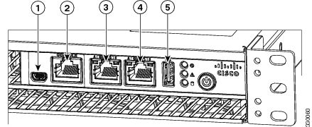
Use the following information (see Figure 3-6) when connecting peripheral cables to the WAVE appliance.
|
Warning |
|
Warning |
Figure 3-6 Cable Connections—Front
|
|
Console port (mini-USB) |
|
10/100/1000 GE 0/1 connector |
|
|
Console port (RJ-45) |
|
External USB port |
|
|
10/100/1000 GE 0/0 connector |
Connecting Power and Booting the System
To connect power to your system, follow these steps:
Step 1 ![]() Review the information in the "Safety Guidelines" section.
Review the information in the "Safety Guidelines" section.
Step 2 ![]() Plug a power cord into the power cord receptacle on the back of the WAVE appliance.
Plug a power cord into the power cord receptacle on the back of the WAVE appliance.
Step 3 ![]() Connect the other end of the power cord to a power source at your installation site.
Connect the other end of the power cord to a power source at your installation site.
Step 4 ![]() Power up all externally connected devices.
Power up all externally connected devices.
Step 5 ![]() Press the power control button on the front of the WAVE appliance.
Press the power control button on the front of the WAVE appliance.
The system should begin booting. Once the operating system boots, you are ready to initialize the basic software configuration. (See the software configuration guide for details.)
|
Note |
Checking the LEDs
When the WAVE-294 is up and running, observe the front panel LEDs (see Figure 1-1 and Table 1-1) to verify that your system is operating properly.
To troubleshoot using the LEDs, see Chapter 6 "Troubleshooting the System Hardware."
Removing or Replacing a WAVE Appliance
To remove a WAVE appliance from your network, power it down, disconnect the power cords and network cables, and physically remove the chassis from the rack.
The WAVE appliance is in constant communication with the router on your network. When the router notices that the WAVE appliance is no longer responding to it, the router stops sending requests to the WAVE appliance. This action is transparent to users. If other WAVE appliances are attached to the router, the router continues sending requests to the other WAVE appliances.
When you remove a WAVE appliance, the pages that were cached on that appliance are no longer available to the router or other WAVE appliances. You might see an increase in outgoing web traffic that might have otherwise been fulfilled by the WAVE appliance that you are removing. However, after a time, the router and other WAVE appliances redistribute the load of web traffic.
If you remove the last WAVE appliance from your network, you can also disable WAVE support on the router. However, this action is not necessary because leaving WAVE support enabled when there are no WAVE appliances attached has no effect on the router's performance.
To replace a WAVE appliance, remove it from the network, and then install a new WAVE appliance and configure it using the same configuration parameters (IP address and so forth) that you used for the removed WAVE appliance.
 Feedback