Release 6.0: Cisco Vision Director Data Integration Guide
Bias-Free Language
The documentation set for this product strives to use bias-free language. For the purposes of this documentation set, bias-free is defined as language that does not imply discrimination based on age, disability, gender, racial identity, ethnic identity, sexual orientation, socioeconomic status, and intersectionality. Exceptions may be present in the documentation due to language that is hardcoded in the user interfaces of the product software, language used based on RFP documentation, or language that is used by a referenced third-party product. Learn more about how Cisco is using Inclusive Language.
- Updated:
- November 30, 2017
Chapter: Configuring Data Integration in Cisco Vision Director
- Before You Begin
- Prerequisites for Configuring NFL GSIS Integration
- Prerequisites for Configuring OES ISC9000 Scoreboard Integration
- Prerequisites for Configuring Daktronics All Sport 5000 Scoreboard Integration
- Prerequisites for Configuring Generic Data Sources
- Prerequisites for Configuring POS Data Sources
- Prerequisites for Configuring RSS and Atom Data Sources
- Workflow Summary for Data Integration
- How to Configure Data Integration
- Accessing the Data Integration Interface
- Adding a New Data Source
- Configuring the Network Connection to the Data Source
- Configuring the Connection to an Atom or RSS Feed
- Configuring the Connection to a Generic Data Source
- Configuring the Connection to a Generic POS Data Source
- Configuring the Connection to an Internal Database POS Data Source
- Configuring the Connection to a Menu Theme POS Data Source
- Configuring the Connection to the NFL GSIS SIAB Server
- Configuring the Connection to the Scoreboard Controllers
- Configuring Data Options
- Configuring the Image Display Size for Atom and RSS Feeds
- Providing Sample XML or JSON Data for Generic Data Sources
- Selecting Input Statistics and Mapping to Output Fields for Display
- Enabling the Data Source Configuration
- Activating Data Integration System-Wide From the Management Dashboard
- Restarting the Data Integration Application
- Verifying the Integration
- Modifying the Default Data Throttling
Configuring Data Integration in Cisco Vision Dynamic Signage Director
First Published: August 2, 2012
Last Updated: November 15, 2017
This module describes the requirements and how to configure support for data sources in Cisco Vision Director.
This module includes the following topics:
■![]() Workflow Summary for Data Integration
Workflow Summary for Data Integration
■![]() How to Configure Data Integration
How to Configure Data Integration
Before You Begin
Before you configure Cisco Vision Director for Data Integration, be sure that the following requirements are met for the system that you are integrating with:
■![]() Prerequisites for Configuring NFL GSIS Integration
Prerequisites for Configuring NFL GSIS Integration
■![]() Prerequisites for Configuring OES ISC9000 Scoreboard Integration
Prerequisites for Configuring OES ISC9000 Scoreboard Integration
■![]() Prerequisites for Configuring Daktronics All Sport 5000 Scoreboard Integration
Prerequisites for Configuring Daktronics All Sport 5000 Scoreboard Integration
■![]() Prerequisites for Configuring Generic Data Sources
Prerequisites for Configuring Generic Data Sources
■![]() Prerequisites for Configuring POS Data Sources
Prerequisites for Configuring POS Data Sources
■![]() Prerequisites for Configuring RSS and Atom Data Sources
Prerequisites for Configuring RSS and Atom Data Sources
Prerequisites for Configuring NFL GSIS Integration
Before you configure the National Football League (NFL) Game Statistics and Information System (GSIS) integration, be sure that the following requirements are met:
■![]() The required Cisco Vision Director server hardware is installed and running Cisco Vision Release 6.0 or later.
The required Cisco Vision Director server hardware is installed and running Cisco Vision Release 6.0 or later.
■![]() The NFL Stats-in-a-Box (SIAB) server is installed at the venue and is connected to the NFL GSIS database. Advise your network Administrator to allow communication between these two servers.
The NFL Stats-in-a-Box (SIAB) server is installed at the venue and is connected to the NFL GSIS database. Advise your network Administrator to allow communication between these two servers.
■![]() The SIAB server is reachable by the Cisco Vision Director server on the Internet Protocol (IP) network.
The SIAB server is reachable by the Cisco Vision Director server on the Internet Protocol (IP) network.
■![]() For support of the NFL GSIS clock, a router in the network must be configured for Network Address Translation (NAT) to change the local broadcast address to the unicast IP address of the Cisco Vision Director server.
For support of the NFL GSIS clock, a router in the network must be configured for Network Address Translation (NAT) to change the local broadcast address to the unicast IP address of the Cisco Vision Director server.
–![]() A router in the network is configured for Network Address Translation (NAT) to change the local broadcast address to the unicast IP address of the Cisco Vision Director server.
A router in the network is configured for Network Address Translation (NAT) to change the local broadcast address to the unicast IP address of the Cisco Vision Director server.
TIP : You can verify reachability using the ping command from the Cisco Vision Director server to the SIAB server.
–![]() You have obtained the UDP port number used by the vendor.
You have obtained the UDP port number used by the vendor.
■![]() The NFL GSIS representative has provided the SIAB IP address and account information, which will be needed to configure Cisco Vision Director connectivity to the SIAB server.
The NFL GSIS representative has provided the SIAB IP address and account information, which will be needed to configure Cisco Vision Director connectivity to the SIAB server.
Prerequisites for Configuring OES ISC9000 Scoreboard Integration
Before you configure the OES ISC9000 Intelligent Scoreboard Controller integration, be sure that the following requirements are met:
■![]() The required Cisco Vision Director server hardware is installed and running Cisco Vision Release 6.0 or later.
The required Cisco Vision Director server hardware is installed and running Cisco Vision Release 6.0 or later.
■![]() The OES ISC9000 Scoreboard controller is installed at the venue (preferably in the Cisco Vision network).
The OES ISC9000 Scoreboard controller is installed at the venue (preferably in the Cisco Vision network).
■![]() The OES ISC9000 Scoreboard controller is reachable by the Cisco Vision Director server on the Internet Protocol (IP) network.
The OES ISC9000 Scoreboard controller is reachable by the Cisco Vision Director server on the Internet Protocol (IP) network.
■![]() A site Administrator or OES equipment vendor has added the Cisco Vision Director server IP address and UDP port number in the OES controller.
A site Administrator or OES equipment vendor has added the Cisco Vision Director server IP address and UDP port number in the OES controller.
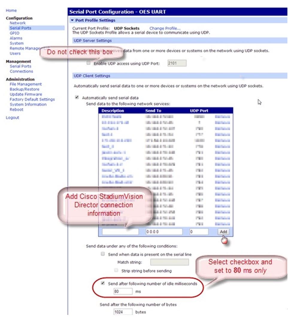
NOTE : Be sure to record the UDP port number used in the OES ISC9000 controller so that you can configure the same port in the network connection information for Cisco Vision Director.
OES ISC9000 Configuration shows an example of the interface for the Serial Port Configuration on the OES ISC9000 controller where the Cisco Vision Director server information must be added.
Figure 1 OES ISC9000 Configuration
Prerequisites for Configuring Daktronics All Sport
5000 Scoreboard Integration
Before you configure the Daktronics All Sport 5000 Scoreboard integration, be sure that the following requirements are met:
■![]() The required Cisco Vision Director server hardware is installed and running Cisco Vision Release 6.0.
The required Cisco Vision Director server hardware is installed and running Cisco Vision Release 6.0.
■![]() The Daktronics Scoreboard controller is installed at the venue (preferably in the Cisco Vision network).
The Daktronics Scoreboard controller is installed at the venue (preferably in the Cisco Vision network).
■![]() The Daktronics Scoreboard controller is reachable by the Cisco Vision Director server on the Internet Protocol (IP) network.
The Daktronics Scoreboard controller is reachable by the Cisco Vision Director server on the Internet Protocol (IP) network.
■![]() The Lantronix UDS 1100-POE Device Server is installed on the network.
The Lantronix UDS 1100-POE Device Server is installed on the network.
■![]() A computer is set up with the Daktronics Scoring and Timing Interface (DSTI) software and has two serial ports available (or use two USB ports with USB-to-serial adapter cables).
A computer is set up with the Daktronics Scoring and Timing Interface (DSTI) software and has two serial ports available (or use two USB ports with USB-to-serial adapter cables).
■![]() If using the Daktronics scoreboard for NBA basketball, be sure that the Daktronics software uses Rev 1 of the Daktronics Basketball TV Feed Specification for compatibility with Cisco Vision Director Release 4.0 and Release 4.1.A.
If using the Daktronics scoreboard for NBA basketball, be sure that the Daktronics software uses Rev 1 of the Daktronics Basketball TV Feed Specification for compatibility with Cisco Vision Director Release 4.0 and Release 4.1.A.
TIP: The basketball protocol changes whenever there are NBA rules changes—contact your Daktronics representative to determine your protocol version.
■![]() Be sure that you have the UDP port number that is hard-coded in the DSTI configuration file so that you can configure the same port in the network connection information for Cisco Vision Director.
Be sure that you have the UDP port number that is hard-coded in the DSTI configuration file so that you can configure the same port in the network connection information for Cisco Vision Director.
■![]() You have the Daktronics configuration file with the baud rate and port information.
You have the Daktronics configuration file with the baud rate and port information.
■![]() You have the IP address of the Cisco Vision Director server.
You have the IP address of the Cisco Vision Director server.
■![]() The Daktronics Scoreboard controller is reachable by the Cisco Vision Director server on the network.
The Daktronics Scoreboard controller is reachable by the Cisco Vision Director server on the network.
■![]() The devices are connected using straight-through DB-25 male to DB-9 female serial cables:
The devices are connected using straight-through DB-25 male to DB-9 female serial cables:
–![]() The scoreboard controller is connected to the DSTI computer.
The scoreboard controller is connected to the DSTI computer.
–![]() The DSTI computer is connected to the Lantronix device serial port.
The DSTI computer is connected to the Lantronix device serial port.
■![]() You have completed the following configuration tasks on the Daktronics scoreboard controller, DSTI computer, and Lantronix devices:
You have completed the following configuration tasks on the Daktronics scoreboard controller, DSTI computer, and Lantronix devices:
–![]() Configuring the Serial Ports on all Devices (required)
Configuring the Serial Ports on all Devices (required)
–![]() Configuring the Network Connections (required)
Configuring the Network Connections (required)
Configuring the Serial Ports on all Devices
■![]() Configure the serial COM port on the Daktronics scoreboard controller with the following settings:
Configure the serial COM port on the Daktronics scoreboard controller with the following settings:
NOTE: Use the baud rate in the configuration file provided by Daktronics. For example, it could be 19200.
■![]() Configure all serial COM ports on the DSTI computer, and Lantronix device with the following settings:
Configure all serial COM ports on the DSTI computer, and Lantronix device with the following settings:
NOTE : Be sure that the serial ports on the DSTI computer and Lantronix device have matching baud rates.
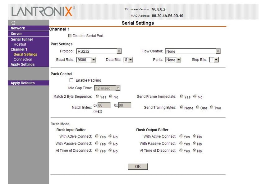
Daktronics All Sport 5000 Configuration shows the serial configuration on the Lantronix device.
Figure 2 Lantronix USD 1100-POE Serial Settings
Configuring the Network Connections
Be sure that the Lantronix device and the DSTI software is network connections are configured:
■![]() Using the port information provided in the Daktronics configuration file, configure the Lantronix device connection settings for the UDP protocol, Daktronics port, and the IP address of the Cisco Vision Director server as shown in the example in Figure 3
Using the port information provided in the Daktronics configuration file, configure the Lantronix device connection settings for the UDP protocol, Daktronics port, and the IP address of the Cisco Vision Director server as shown in the example in Figure 3
Figure 3 Lantronix USD 1100-POE Connection Settings

■![]() In the Hostlist settings on the Lantronix device, configure the IP address of the Cisco Vision Director server and port as shown in the example in Figure 4.
In the Hostlist settings on the Lantronix device, configure the IP address of the Cisco Vision Director server and port as shown in the example in Figure 4.
Figure 4 Lantronix UDS 1100-POE Hostlist Settings

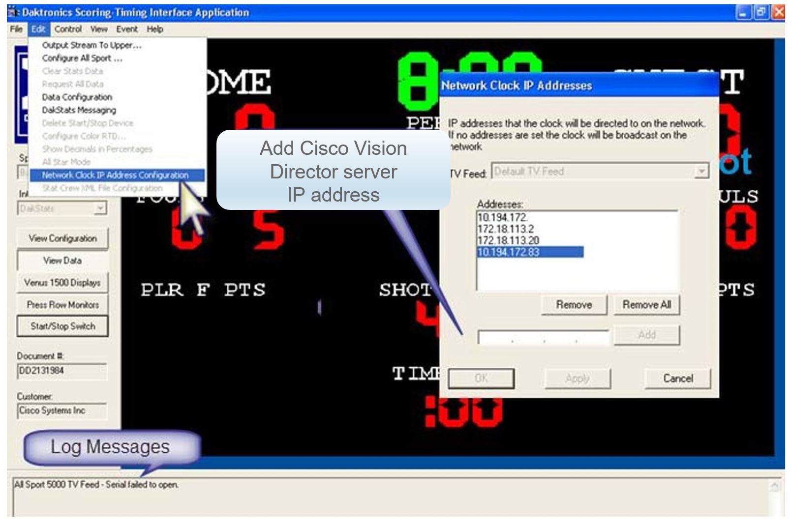
■![]() Configure the DSTI application for the Daktronics controller with the IP address of the Cisco Vision Director server as shown in the example in Figure 5.
Configure the DSTI application for the Daktronics controller with the IP address of the Cisco Vision Director server as shown in the example in Figure 5.
Figure 5 Daktronics All Sport 5000 Configuration
Prerequisites for Configuring Generic Data Sources
Before you configure generic data sources, be sure that the following requirements are met:
■![]() You know the message type of the data source (TCP, HTTP, UDP, FTP, or Database).
You know the message type of the data source (TCP, HTTP, UDP, FTP, or Database).
■![]() You have the corresponding connection information for the specified message type.
You have the corresponding connection information for the specified message type.
■![]() You have a copy of one unique sector of the XML data from the source feed that can be used as sample data for the External Content Integration configuration or a sample file that can be uploaded to Cisco Vision Director.
You have a copy of one unique sector of the XML data from the source feed that can be used as sample data for the External Content Integration configuration or a sample file that can be uploaded to Cisco Vision Director.
■![]() Cisco Vision Director must be able to reach any externally referenced source data (for example, referenced images) on the network
Cisco Vision Director must be able to reach any externally referenced source data (for example, referenced images) on the network
■![]() You are aware of the following dependencies for proper rendition of fonts:
You are aware of the following dependencies for proper rendition of fonts:
For information about installing fonts, see the “Using the Software Manager to Upgrade Cisco Vision Director Software, Language Packs, and Fonts” module in the Cisco Vision Director Software Installation and Upgrade Guide.
–![]() For the SV-4K or DMP-2K—Most unicode characters can be rendered as part of the DMP system fonts. This means that the system font is available as a substitution font to HTML pages or feeds that might not explicitly reference web fonts in their CSS.
For the SV-4K or DMP-2K—Most unicode characters can be rendered as part of the DMP system fonts. This means that the system font is available as a substitution font to HTML pages or feeds that might not explicitly reference web fonts in their CSS.
Prerequisites for Configuring POS Data Sources
Cisco Vision Director supports the following types of POS data sources: Generic PoS, Internal Database PoS, and Menu Theme. Before you configure a POS data source, be sure that you understand the differences between these types and when to use them by seeing Information About POS Data Sources in Cisco Vision Director.
This section includes the following topics:
■![]() Prerequisites for Generic POS Data Sources
Prerequisites for Generic POS Data Sources
Prerequisites for Generic POS Data Sources
Before you configure generic POS data sources, be sure that the following conditions are met:
■![]() POS vendors host an API over HTTP/HTTPS for menu retrieval, and you have the URL for the vendor API.
POS vendors host an API over HTTP/HTTPS for menu retrieval, and you have the URL for the vendor API.
■![]() POS data must conform to Cisco Vision Director POS API XML schema. You must have the vendor name and store name for the data source.
POS data must conform to Cisco Vision Director POS API XML schema. You must have the vendor name and store name for the data source.
■![]() If you want to categorize menu items into groups, then you should have a data source for each menu category from the POS vendor.
If you want to categorize menu items into groups, then you should have a data source for each menu category from the POS vendor.
Prerequisites for Internal Database POS Data Sources
Before you configure internal database POS data sources, be sure that the following requirements are met:
■![]() You have an existing Micros or Quest POS configuration in Cisco Vision Director using stores.
You have an existing Micros or Quest POS configuration in Cisco Vision Director using stores.
■![]() You accept that all menu data is ingested as one data source without support for category groupings.
You accept that all menu data is ingested as one data source without support for category groupings.
Prerequisites for Menu Theme POS Data Sources
Before you configure menu theme POS data sources, be sure that the following requirements are met:
■![]() You already support menus in DMB using Cisco or POS stores.
You already support menus in DMB using Cisco or POS stores.
■![]() You have created menus for the stores using DMB themes.
You have created menus for the stores using DMB themes.
■![]() You want to support groups on your menu and use the Widgets tool to design the layout of your menu.
You want to support groups on your menu and use the Widgets tool to design the layout of your menu.
■![]() Data changes, such as price updates, must be made in the DMB application.
Data changes, such as price updates, must be made in the DMB application.
Prerequisites for Configuring RSS and Atom Data Sources
Before you configure RSS data sources, be sure that the following requirements are met:
■![]() You have the source URL for the data feed.
You have the source URL for the data feed.
■![]() You are aware of the following dependencies for proper rendition of fonts:
You are aware of the following dependencies for proper rendition of fonts:
For information about installing fonts, see the “Using the Software Manager to Upgrade Cisco Vision Director Software, Language Packs, and Fonts” module in the Cisco Vision Director Software Installation and Upgrade Guide.
–![]() For the SV-4K or DMP-2K—Most unicode characters can be rendered as part of the DMP system fonts. This means that the system font is available as a substitution font to HTML pages or feeds that might not explicitly reference web fonts in their CSS.
For the SV-4K or DMP-2K—Most unicode characters can be rendered as part of the DMP system fonts. This means that the system font is available as a substitution font to HTML pages or feeds that might not explicitly reference web fonts in their CSS.
Workflow Summary for Data Integration
NOTE : This workflow assumes that you have completed the required backend network installation and integration at your venue for the external data sources that you plan to support, such as with the NFL GSIS network and Stats-in-a-Box (SIAB) server, or scoreboard device.
The following steps summarize the overall workflow to integrate data into Cisco Vision Director and display that content on a TV (Figure 6).
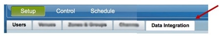
Control Panel Setup Interface—Data Integration Tab
1.![]() From the Control Panel, access the Data Integration interface.
From the Control Panel, access the Data Integration interface.
2.![]() Select the data source that you want to configure.
Select the data source that you want to configure.
3.![]() Complete the network connection configuration.
Complete the network connection configuration.
4.![]() Modify any configuration options, such as data throttling, as applicable.
Modify any configuration options, such as data throttling, as applicable.
5.![]() Enable the configuration and save the configuration.
Enable the configuration and save the configuration.
6.![]() Enable the data source (click Deploy).
Enable the data source (click Deploy).
NOTE : Whenever you modify and save the Data Integration configuration, you must activate and restart the application in the Management Dashboard. Cisco Vision Director prompts you to do this; it can be done at this step or after you finish mapping and formatting your statistics.
Figure 6 Data Integration Configuration Workflow
NOTE : For generic data sources, provide sample XML data before you complete field mapping.
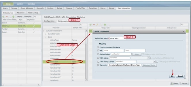
7.![]() Format each statistic to set the output field name and any other output criteria as desired (Figure 7). Click OK. Save the mapping.
Format each statistic to set the output field name and any other output criteria as desired (Figure 7). Click OK. Save the mapping.
Figure 7 Field Mapping Workflow
Management Dashboard—Data Integration
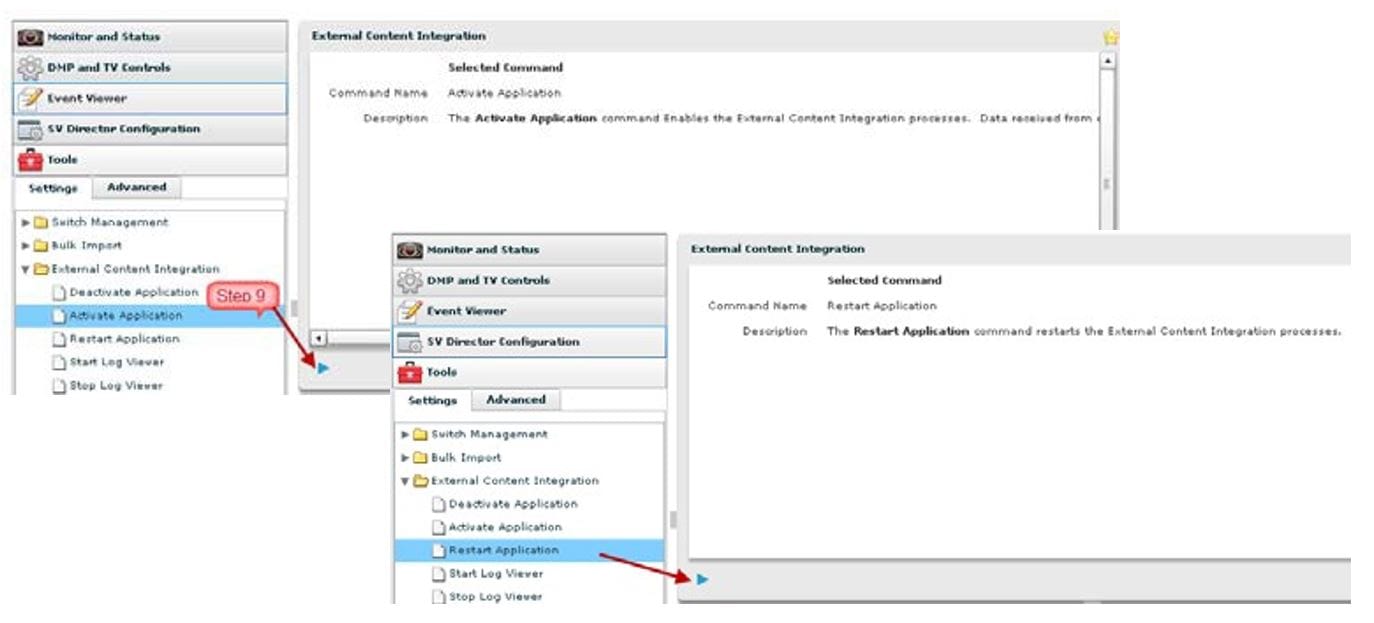
8.![]() Activate and restart the Data Integration application from the Management Dashboard (Figure 8).
Activate and restart the Data Integration application from the Management Dashboard (Figure 8).
Figure 8 Data Integration Application in Management Dashboard
Control Panel Widgets Interface
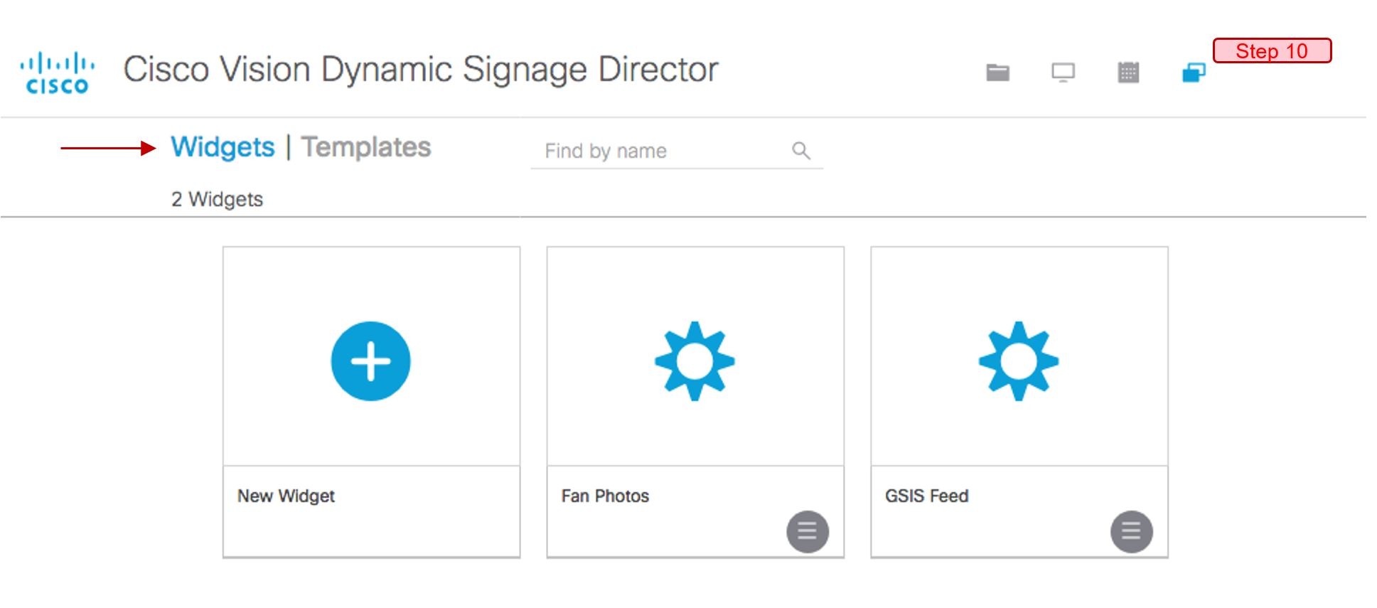
9.![]() Use the Widgets tool from the Main Menu to design a layout of the statistics that you configured to add graphics and bind/position data fields and save the widget (Figure 9). See Designing the Layout of Content Using the Widgets Tool for more information.
Use the Widgets tool from the Main Menu to design a layout of the statistics that you configured to add graphics and bind/position data fields and save the widget (Figure 9). See Designing the Layout of Content Using the Widgets Tool for more information.
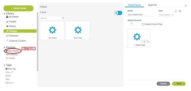
10.![]() Create a playlist from the Main Menu for the widget that you created (Figure 10). Widgets are categorized in the “By Type” folder under the “widget” type.
Create a playlist from the Main Menu for the widget that you created (Figure 10). Widgets are categorized in the “By Type” folder under the “widget” type.
Figure 10 Create Playlist from Main Menu
11.![]() Create an event script to run the playlist.
Create an event script to run the playlist.
12.![]() Schedule the script to display the content on a TV just like other pieces of content in Cisco Vision Director.
Schedule the script to display the content on a TV just like other pieces of content in Cisco Vision Director.
How to Configure Data Integration
This section includes the following tasks:
■![]() Accessing the Data Integration Interface (required)
Accessing the Data Integration Interface (required)
■![]() Adding a New Data Source (required)
Adding a New Data Source (required)
■![]() Configuring the Network Connection to the Data Source (required)
Configuring the Network Connection to the Data Source (required)
■![]() Configuring Data Options (optional)
Configuring Data Options (optional)
■![]() Configuring the Image Display Size for Atom and RSS Feeds
Configuring the Image Display Size for Atom and RSS Feeds
■![]() Providing Sample XML or JSON Data for Generic Data Sources
Providing Sample XML or JSON Data for Generic Data Sources
■![]() Selecting Input Statistics and Mapping to Output Fields for Display (required)
Selecting Input Statistics and Mapping to Output Fields for Display (required)
■![]() Enabling the Data Source Configuration (required)
Enabling the Data Source Configuration (required)
■![]() Activating Data Integration System-Wide From the Management Dashboard (required)
Activating Data Integration System-Wide From the Management Dashboard (required)
■![]() Restarting the Data Integration Application (required)
Restarting the Data Integration Application (required)
■![]() Verifying the Integration (required)
Verifying the Integration (required)
Accessing the Data Integration Interface
To access the data integration interface:
1.![]() Log into Cisco Vision Director as an Administrator.
Log into Cisco Vision Director as an Administrator.
2.![]() From the Main Menu, click Event Management.
From the Main Menu, click Event Management.
3.![]() Click Control Panel. Click the Setup button. Click the Data Integration tab.
Click Control Panel. Click the Setup button. Click the Data Integration tab.
The Data Sources information displays.
Adding a New Data Source
1.![]() From the Data Sources tab view on the Data Integration screen, click the plus (+) icon. The Create new data source connection dialog box displays.
From the Data Sources tab view on the Data Integration screen, click the plus (+) icon. The Create new data source connection dialog box displays.
2.![]() In the Data source name box, type a name for the data source that you want to add.
In the Data source name box, type a name for the data source that you want to add.
TIP: Specify a name using upper or lowercase alphabetical characters, digits 0–9, hyphen (-), or underscore (_).
Spaces are not supported.
3.![]() Under the Type column, select the data source type that you want to add.
Under the Type column, select the data source type that you want to add.
4.![]() (Generic Data Source only) For a Generic Data Source, select the message type from the drop-down box.
(Generic Data Source only) For a Generic Data Source, select the message type from the drop-down box.
5.![]() Click Create. The New Data Source displays in the Data Sources panel view and the Configuration panel displays.
Click Create. The New Data Source displays in the Data Sources panel view and the Configuration panel displays.
What To Do Next
Configure the network connection for your data source type. For more information, see Configuring the Network Connection to the Data Source.
Configuring the Network Connection to the Data Source
Complete one or more of the following tasks according to the external data sources that your site is going to use:
■![]() Configuring the Connection to an Atom or RSS Feed
Configuring the Connection to an Atom or RSS Feed
■![]() Configuring the Connection to a Generic Data Source
Configuring the Connection to a Generic Data Source
■![]() Configuring the Connection to a Generic POS Data Source
Configuring the Connection to a Generic POS Data Source
■![]() Configuring the Connection to an Internal Database POS Data Source
Configuring the Connection to an Internal Database POS Data Source
■![]() Configuring the Connection to a Menu Theme POS Data Source
Configuring the Connection to a Menu Theme POS Data Source
Configuring the Connection to an Atom or RSS Feed
To configure the connection to an Atom or RSS feed:
1.![]() Go to the Configuration screen for the selected Atom Feed or RSS Feed data source.
Go to the Configuration screen for the selected Atom Feed or RSS Feed data source.
2.![]() In the Network settings section, specify the URL in the Data source URL address box (Figure 11):
In the Network settings section, specify the URL in the Data source URL address box (Figure 11):
Figure 11 RSS Network Configuration

3.![]() Click Save. A message box appears asking you to restart the application.
Click Save. A message box appears asking you to restart the application.
4.![]() If you have completed all of the changes that you want to make on the Configuration tab, restart the application.
If you have completed all of the changes that you want to make on the Configuration tab, restart the application.
For more information, see Restarting the Data Integration Application.
What To Do Next
Configure the data options as needed for the Atom or RSS feed data source. For more information, see Configuring Data Options.
Configuring the Connection to a Generic Data Source
The connection settings for a generic data source type depend on the message type that is configured when creating the data source. The generic data source can be configured to support one of the following message types:
In addition, each generic data source connection type allows you to specify either JSON or XML data format.
To configure the connection to the generic data source:
1.![]() Go to the Configuration screen for the selected Generic Data Source name.
Go to the Configuration screen for the selected Generic Data Source name.
2.![]() Do one of the following to specify the generic data source location:
Do one of the following to specify the generic data source location:
To configure the connection using FTP, specify the following information (Figure 12):
Figure 12 Generic Data Source Configuration FTP

■![]() Server (IP address)—IP address of the FTP server.
Server (IP address)—IP address of the FTP server.
■![]() Port—FTP port used in Cisco Vision Director for the FTP server connection. The default is 21.
Port—FTP port used in Cisco Vision Director for the FTP server connection. The default is 21.
■![]() Data path—Folder path for the data. The default is “/”.
Data path—Folder path for the data. The default is “/”.
■![]() User—Username for the FTP server connection.
User—Username for the FTP server connection.
■![]() Password—Password for the user account on the FTP server.
Password—Password for the user account on the FTP server.
■![]() Polling frequency—Number (in seconds) that specifies how often to poll data from the source. The default is 60.
Polling frequency—Number (in seconds) that specifies how often to poll data from the source. The default is 60.
■![]() File name filter—Fully-qualified file name or file name with an asterisk (*) wildcard
File name filter—Fully-qualified file name or file name with an asterisk (*) wildcard
To configure the connection using HTTP, specify the following information (Figure 13):
Figure 13 Generic Data Source Configuration: HTTP

■![]() HTTP URL—Fully qualified HTTP or HTTPS URL to the data source.
HTTP URL—Fully qualified HTTP or HTTPS URL to the data source.
■![]() Polling frequency—Number (in seconds) that specifies how often to poll data from the source. The default is 60.
Polling frequency—Number (in seconds) that specifies how often to poll data from the source. The default is 60.
To configure the connection using TCP or UDP, specify the following information (Figure 14):
Figure 14 Generic Data Source Configuration: TCP and UDP
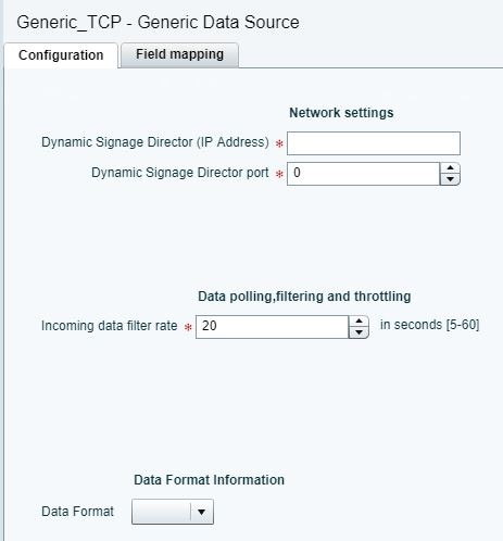
■![]() Cisco Vision Director (IP Address)
Cisco Vision Director (IP Address)
To configure the connection for a Database, specify the following information (Figure 15):
Figure 15 Generic Data Source Configuration: Database

■![]() Database—Name of the database. Supported values are: MySQL (default), PostgreSQL, or SQLServer.
Database—Name of the database. Supported values are: MySQL (default), PostgreSQL, or SQLServer.
NOTE : Do not use Underscore characters “_” in the database name.
■![]() Host—IP address of the server where the database is hosted.
Host—IP address of the server where the database is hosted.
■![]() Port—Server port where the database is hosted. Default is 3306.
Port—Server port where the database is hosted. Default is 3306.
■![]() Schema—Name of the database schema or instance.
Schema—Name of the database schema or instance.
■![]() Username—Name of the user for authentication to access the database.
Username—Name of the user for authentication to access the database.
■![]() Password—Password for the specified Username for authentication to access the database.
Password—Password for the specified Username for authentication to access the database.
■![]() Table Name—Name of the table in the database to retrieve data from.
Table Name—Name of the table in the database to retrieve data from.
■![]() Number of Rows to Retrieve (-1 for all)—Number of data rows to be retrieved from the table.
Number of Rows to Retrieve (-1 for all)—Number of data rows to be retrieved from the table.
3.![]() (For all message types except Database) In the Data Format drop-down box, select JSON or XML to correspond to the data format of the source you are configuring.
(For all message types except Database) In the Data Format drop-down box, select JSON or XML to correspond to the data format of the source you are configuring.
4.![]() Click Save. A message box appears asking you to restart the application.
Click Save. A message box appears asking you to restart the application.
If you have completed all of the changes that you want to make on the Configuration tab, restart the application.
For more information, see Restarting the Data Integration Application.
What To Do Next
Provide sample XML or JSON data for the generic data source. For more information, see Providing Sample XML or JSON Data for Generic Data Sources.
Configuring the Connection to a Generic POS Data Source
Use the Generic POS data source under the following conditions:
■![]() You need to support POS data from a vendor other than Quest or Micros.
You need to support POS data from a vendor other than Quest or Micros.
■![]() You only want to use Data Integration and the Widgets tool for your menu creation.
You only want to use Data Integration and the Widgets tool for your menu creation.
To configure the connection to the generic POS data source:
1.![]() Go to the Configuration screen for the selected generic POS data source name.
Go to the Configuration screen for the selected generic POS data source name.
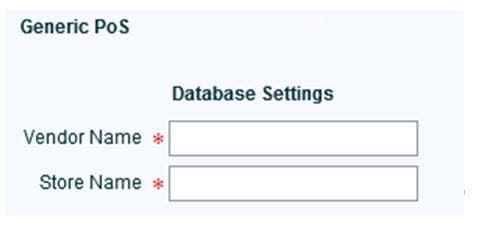
2.![]() Specify the Database Settings (Figure 16):
Specify the Database Settings (Figure 16):
Figure 16 Generic POS—Database Settings
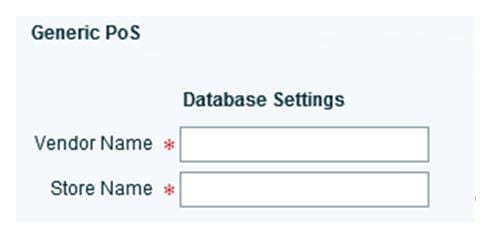
■![]() Vendor Name (required)—Name of the vendor for the POS data source.
Vendor Name (required)—Name of the vendor for the POS data source.
3.![]() Specify the Network Settings (Figure 17):
Specify the Network Settings (Figure 17):
Figure 17 Generic POS—Network Settings
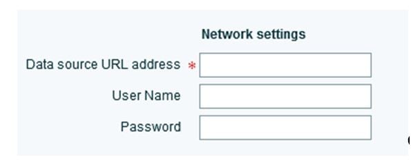
■![]() Data source URL address (required)—HTTP or HTTPS URL of the POS vendor API.
Data source URL address (required)—HTTP or HTTPS URL of the POS vendor API.
If an HTTPS URL is specified, the User Name and Password must be specified for authentication.
4.![]() Specify the Polling Interval (required)—Number (in seconds) for the frequency to poll data from the source feed. Default is 60. (Figure 18):
Specify the Polling Interval (required)—Number (in seconds) for the frequency to poll data from the source feed. Default is 60. (Figure 18):
Figure 18 Generic POS—Polling Interval

5.![]() Specify the dimensions to which menu item images are resized (Figure 19).
Specify the dimensions to which menu item images are resized (Figure 19).
Figure 19 Generic POS—Image Display Settings
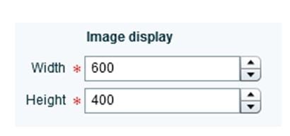
■![]() Width—Number of horizontal pixels. Default is 600.
Width—Number of horizontal pixels. Default is 600.
■![]() Height—Number of vertical pixels. Default is 400.
Height—Number of vertical pixels. Default is 400.
6.![]() Click Save. A message box appears asking you to restart the application.
Click Save. A message box appears asking you to restart the application.
7.![]() If you have completed all of the changes that you want to make on the Configuration tab, restart the application.
If you have completed all of the changes that you want to make on the Configuration tab, restart the application.
For more information, see Restarting the Data Integration Application.
Configuring the Connection to an Internal Database POS Data Source
Use the internal database POS data source under the following conditions:
■![]() You have very simple menu data.
You have very simple menu data.
■![]() You only need your menu data to appear in a single list.
You only need your menu data to appear in a single list.
■![]() You already use Quest or Micros POS but want to build Menu Boards using Widgets instead of the DMB application.
You already use Quest or Micros POS but want to build Menu Boards using Widgets instead of the DMB application.
To configure the connection to an internal database POS data source:
1.![]() Go to the Configuration screen for the selected internal database POS data source name.
Go to the Configuration screen for the selected internal database POS data source name.
2.![]() Specify the Database Settings (Figure 20):
Specify the Database Settings (Figure 20):
Figure 20 Internal Database POS—Database Settings
■![]() Vendor Name (required)—Name of the existing DMB vendor already integrated with Cisco Vision Director to be the POS data source. Possible values are Micros or Quest.
Vendor Name (required)—Name of the existing DMB vendor already integrated with Cisco Vision Director to be the POS data source. Possible values are Micros or Quest.
■![]() Store Name (required)—Name of the store configured in the DMB application for the vendor.
Store Name (required)—Name of the store configured in the DMB application for the vendor.
3.![]() Specify the Polling Interval (required)—Number (in seconds) for the frequency to poll data from the source feed. Default is 60. (Figure 21):
Specify the Polling Interval (required)—Number (in seconds) for the frequency to poll data from the source feed. Default is 60. (Figure 21):
Figure 21 Internal Database POS—Polling Interval

4.![]() Click Save. A message box appears asking you to restart the application.
Click Save. A message box appears asking you to restart the application.
5.![]() If you have completed all of the changes that you want to make on the Configuration tab, restart the application.
If you have completed all of the changes that you want to make on the Configuration tab, restart the application.
For more information, see Restarting the Data Integration Application.
Configuring the Connection to a Menu Theme POS Data Source
Use the Menu Theme POS data source under the following conditions:
■![]() You already support menus in DMB using Cisco or POS stores.
You already support menus in DMB using Cisco or POS stores.
■![]() You have created menus for the stores using DMB themes.
You have created menus for the stores using DMB themes.
■![]() You want to support groups on your menu and use the Widgets tool to design the layout of your menu.
You want to support groups on your menu and use the Widgets tool to design the layout of your menu.
To configure the connection to a menu theme POS data source:
1.![]() Go to the Configuration screen for the selected menu theme POS data source name.
Go to the Configuration screen for the selected menu theme POS data source name.
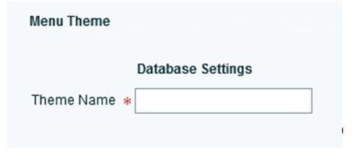
2.![]() Under Database Settings, specify the Theme Name (required) (Figure 22):
Under Database Settings, specify the Theme Name (required) (Figure 22):
NOTE : This Theme Name must match the name configured in the DMB application.
Figure 22 Menu Theme POS—Database Settings
3.![]() Specify the Polling Interval (required)—Number (in seconds) for the frequency to poll data from the DMB application. Default is 60. (Figure 23):
Specify the Polling Interval (required)—Number (in seconds) for the frequency to poll data from the DMB application. Default is 60. (Figure 23):
Figure 23 Internal Database POS—Polling Interval
4.![]() Click Save. A message box appears asking you to restart the application.
Click Save. A message box appears asking you to restart the application.
5.![]() If you have completed all of the changes that you want to make on the Configuration tab, restart the application.
If you have completed all of the changes that you want to make on the Configuration tab, restart the application.
For more information, see Restarting the Data Integration Application.
Configuring the Connection to the NFL GSIS SIAB Server
This section includes the following topics:
■![]() Configuring the Network Settings for NFL Cumulative Statistics
Configuring the Network Settings for NFL Cumulative Statistics
Configuring the Network Settings for NFL Cumulative Statistics
NOTE : Before you configure the FTP connection, be sure that you have the IP address and account credentials for the SIAB server from your NFL GSIS representative.
Cisco Vision Director uses FTP port 21 to communicate to the NFL GSIS SIAB server to obtain the GSIS statistics.
To configure the network connection to the NFL GSIS SIAB server:
1.![]() Go to Control Panel > Setup > Data Integration > Data sources.
Go to Control Panel > Setup > Data Integration > Data sources.
2.![]() Select the GSIS: NFL, Cumulative Statistics data source type.
Select the GSIS: NFL, Cumulative Statistics data source type.
3.![]() Click the Configuration tab.
Click the Configuration tab.
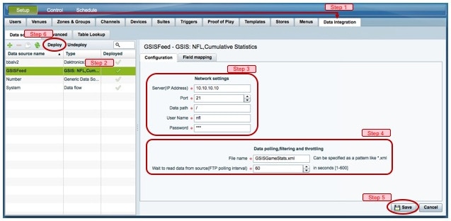
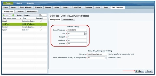
4.![]() In the Network settings section, configure the following options (Figure 24):
In the Network settings section, configure the following options (Figure 24):
a.![]() In the Server (IP Address) box, type the IP address of the SIAB server.
In the Server (IP Address) box, type the IP address of the SIAB server.
b.![]() In the Port box, type 21. The default is 21.
In the Port box, type 21. The default is 21.
c.![]() In the Data path box, type “ / ”. The default is /.
In the Data path box, type “ / ”. The default is /.
d.![]() In the User box, type the username for the SIAB server account. The default is nfl.
In the User box, type the username for the SIAB server account. The default is nfl.
e.![]() In the Password box, type the password for the SIAB server account. The default is nfl.
In the Password box, type the password for the SIAB server account. The default is nfl.
Figure 24 NFL Cumulative Statistics Network Configuration
5.![]() Click Save. A message box appears asking you to restart the application.
Click Save. A message box appears asking you to restart the application.
6.![]() If you have completed all of the changes that you want to make on the Configuration tab, restart the application.
If you have completed all of the changes that you want to make on the Configuration tab, restart the application.
For more information, see Restarting the Data Integration Application.
Configuring the UDP Connection for the NFL Game Clock
NOTE : Acquire the UDP port number to communicate with the NFL GSIS SIAB server to obtain the GSIS game clock.
To configure the UDP connection for the NFL game clock:
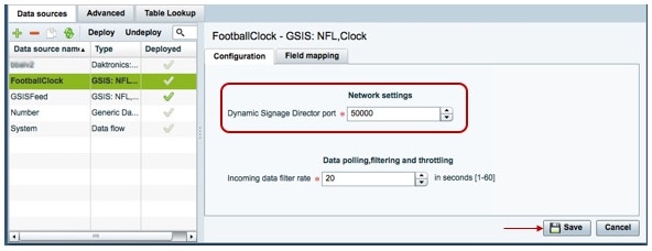
1.![]() Go to the Configuration screen for the selected GSIS: NFL,Clock data source.
Go to the Configuration screen for the selected GSIS: NFL,Clock data source.
2.![]() In the Network settings section, configure the following options (Figure 25):
In the Network settings section, configure the following options (Figure 25):
a.![]() In the Cisco Vision Director (IP Address) box, type the IP address of the Cisco Vision server.
In the Cisco Vision Director (IP Address) box, type the IP address of the Cisco Vision server.
TIP: The actual IP address of the Cisco Vision server that you are logged into is provided in shadow, but you must type the address in the box to configure it.
b.![]() In the Cisco Vision Director port box, type the port number being used by the GSIS server. The default is 0.In the left pane, select the GSIS: NFL,Clock data source type.
In the Cisco Vision Director port box, type the port number being used by the GSIS server. The default is 0.In the left pane, select the GSIS: NFL,Clock data source type.
Figure 25 NFL Game Clock Network Configuration
3.![]() Click Save. A message box appears asking you to restart the application.
Click Save. A message box appears asking you to restart the application.
4.![]() If you have completed all of the changes that you want to make on the Configuration tab, restart the application.
If you have completed all of the changes that you want to make on the Configuration tab, restart the application.
For more information, see Restarting the Data Integration Application.
What To Do Next
Configure the data options for the NFL Clock data source. For more information, see Configuring the Incoming Data Filter Rate for Data Sources.
Configuring the Connection to the Scoreboard Controllers
Cisco Vision Director uses a UDP port to communicate to the controllers to obtain the scoreboard statistics.
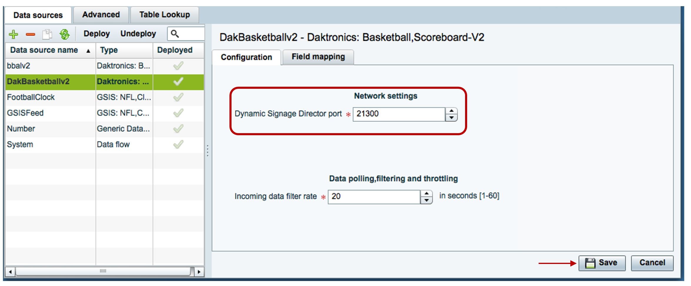
NOTE : The UDP port for the OES ISC9000 Scoreboard controller varies, but the UDP port for the Daktronics All Sport 5000 Scoreboard controller is always 21300. Be sure that you know the UDP port being used for the scoreboard controller.
To configure the UDP connection to the scoreboard controllers:
1.![]() Go to the Configuration screen for the selected scoreboard data source.
Go to the Configuration screen for the selected scoreboard data source.
2.![]() In the Network settings section, configure the following option (Figure 26):
In the Network settings section, configure the following option (Figure 26):
In the Cisco Vision Director port box, type the UDP port number used to connect to the scoreboard controller.
Figure 26 Daktronics Scoreboard Controller UDP Connection Configuration
3.![]() Click Save. A message box appears asking you to restart the application.
Click Save. A message box appears asking you to restart the application.
4.![]() If you have completed all of the changes that you want to make on the Configuration tab, restart the application.
If you have completed all of the changes that you want to make on the Configuration tab, restart the application.
For more information, see Restarting the Data Integration Application.
What To Do Next
Configure the data options for the scoreboard data source. For more information, see Configuring the Incoming Data Filter Rate for Data Sources.
Configuring Data Options
The data configuration options vary by the data source type:
■![]() Configuring Data Options for Atom and RSS Feeds8
Configuring Data Options for Atom and RSS Feeds8
■![]() Configuring Data Options for Generic Database Sources
Configuring Data Options for Generic Database Sources
Configuring Data Options for Atom and RSS Feeds
To configure data options for Atom and RSS feeds:
1.![]() Go to the Configuration screen for the selected Atom Feed or RSS Feed data source.
Go to the Configuration screen for the selected Atom Feed or RSS Feed data source.
2.![]() In the Data configuration section, set one or more of the following options (Figure 27):
In the Data configuration section, set one or more of the following options (Figure 27):
Figure 27 Data Configuration Options for Atom and RSS Feeds
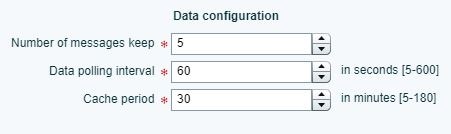
a.![]() Number of messages keep—Number of messages to keep from the feed. The default is 5.
Number of messages keep—Number of messages to keep from the feed. The default is 5.
TIP: If planning to use images from the feed for the PicToScreen component in the Widgets tool, then a maximum of 5 images can be displayed. It is recommended that the number of messages to keep is 5 for images.
b.![]() Data polling interval—Number (in seconds) for the frequency to poll data from the source feed. The default is 60.
Data polling interval—Number (in seconds) for the frequency to poll data from the source feed. The default is 60.
TIP: 60 seconds is the recommended polling interval for images. Consider a longer interval for text feeds.
c.![]() Cache period—Amount of time (in minutes) to retain polled data. The default is 30.
Cache period—Amount of time (in minutes) to retain polled data. The default is 30.
What To Do Next
Configure the image size as needed for the Atom or RSS feed data source. For more information, see Configuring the Image Display Size for Atom and RSS Feeds.
Configuring Data Options for Generic Database Sources
To configure data options for generic database sources:
1.![]() Go to the Configuration screen for the selected generic database data source.
Go to the Configuration screen for the selected generic database data source.
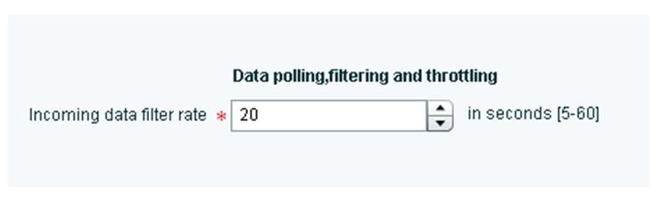
2.![]() In the Data polling, filtering, and throttling section, set one or more of the following options (Figure 28):
In the Data polling, filtering, and throttling section, set one or more of the following options (Figure 28):
Figure 28 Data Configuration Options for Generic Database Sources
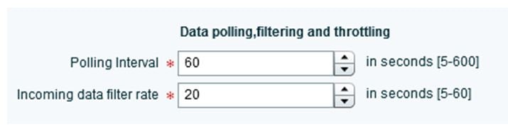
a.![]() Polling interval—Number (in seconds) for the frequency to poll data from the source feed. The default is 60.
Polling interval—Number (in seconds) for the frequency to poll data from the source feed. The default is 60.
b.![]() Incoming data filter rate—Number (in seconds) that specifies the amount of time to ignore duplicate data and process only new data. The default is 20.
Incoming data filter rate—Number (in seconds) that specifies the amount of time to ignore duplicate data and process only new data. The default is 20.
3.![]() Click Save. A message box appears asking you to restart the application.
Click Save. A message box appears asking you to restart the application.
4.![]() If you have completed all of the changes that you want to make on the Configuration tab, restart the application.
If you have completed all of the changes that you want to make on the Configuration tab, restart the application.
For more information, see the Restarting the Data Integration Application.
What To Do Next
Enable the data source. For more information, see Enabling the Data Source Configuration.
Configuring Data Options for NFL Cumulative Statistics
To configure data options for NFL cumulative statistics:
1.![]() Go to the Configuration screen for the selected GSIS: NFL, Cumulative Statistics data source.
Go to the Configuration screen for the selected GSIS: NFL, Cumulative Statistics data source.
2.![]() In the Data polling, filtering, and throttling section, set one or more of the following options (Figure 29):
In the Data polling, filtering, and throttling section, set one or more of the following options (Figure 29):
Figure 29 NFL Cumulative Statistics Data Configuration Options

■![]() File name—Name of the cumulative statistics file on the SIAB server. The default is GSISGameStats.xml.
File name—Name of the cumulative statistics file on the SIAB server. The default is GSISGameStats.xml.
■![]() Wait to read data from source (FTP polling interval)—Number (in milliseconds) that specifies how often to retrieve data from the SIAB server. The default is 60.
Wait to read data from source (FTP polling interval)—Number (in milliseconds) that specifies how often to retrieve data from the SIAB server. The default is 60.
3.![]() Click Save. A message box appears asking you to restart the application.
Click Save. A message box appears asking you to restart the application.
4.![]() If you have completed all of the changes that you want to make on the Configuration tab, restart the application.
If you have completed all of the changes that you want to make on the Configuration tab, restart the application.
For more information, see Restarting the Data Integration Application.
What To Do Next
Enable the data source. For more information, see Enabling the Data Source Configuration.
Configuring the Incoming Data Filter Rate for Data Sources
NOTE: This data option is available for GSIS NFL clock, Daktronics, OES scoreboard, and Generic database data sources.
To configure the incoming data filter rate for data sources:
1.![]() Go to the Configuration screen for the selected NFL clock or scoreboard controller data source.
Go to the Configuration screen for the selected NFL clock or scoreboard controller data source.
2.![]() In the Incoming data filter rate box, specify the number (in seconds) that specifies the amount of time to ignore duplicate data and process only new data (Figure 30). The default is 20.
In the Incoming data filter rate box, specify the number (in seconds) that specifies the amount of time to ignore duplicate data and process only new data (Figure 30). The default is 20.
Figure 30 Incoming Data Filter Rate Options
3.![]() Click Save. A message box appears asking you to restart the application.
Click Save. A message box appears asking you to restart the application.
4.![]() If you have completed all of the changes that you want to make on the Configuration tab, restart the application.
If you have completed all of the changes that you want to make on the Configuration tab, restart the application.
For more information, see Restarting the Data Integration Application.
What To Do Next
Enable the data source. For more information, see Enabling the Data Source Configuration.
Configuring the Image Display Size for Atom and RSS Feeds
Image dimensions are retained from the original source unless you change the image display size options from the default values of width 0 and height 0. If you specify the image width and height, then the source images from that data feed will be resized.
To configure the image display size:
1.![]() Go to the Configuration screen for the selected data source type.
Go to the Configuration screen for the selected data source type.
2.![]() In the Image display section, set one or more of the following options using the spinner control:
In the Image display section, set one or more of the following options using the spinner control:
a.![]() In the Width box, select the horizontal dimension of the image (in pixels).
In the Width box, select the horizontal dimension of the image (in pixels).
b.![]() In the Height box, select the vertical dimension of the image (in pixels).
In the Height box, select the vertical dimension of the image (in pixels).
3.![]() Click Save. A message box appears asking you to restart the application.
Click Save. A message box appears asking you to restart the application.
4.![]() If you have completed all of the changes that you want to make on the Configuration tab, restart the application.
If you have completed all of the changes that you want to make on the Configuration tab, restart the application.
For more information, see Restarting the Data Integration Application.
What To Do Next
Select the input statistics that you want to map for output display. For more information, see Selecting Input Statistics and Mapping to Output Fields for Display.
Providing Sample XML or JSON Data for Generic Data Sources
NOTE : This task is only required when you are configuring a Generic Data Source.
The sample XML/JSON data is used to “train” the system on the content to be expected from the configured generic data source. You can provide sample XML/JSON data for generic data sources in two ways:
■![]() Uploading a sample XML or JSON file (Recommended).
Uploading a sample XML or JSON file (Recommended).
■![]() Pasting a sample of the XML or JSON data.
Pasting a sample of the XML or JSON data.
NOTE : The JSON is internally converted to XML for use by Cisco Vision Director.
Prerequisites
Before you begin this task, be sure that the following requirements are met:
■![]() You have obtained a sample of your XML or JSON data, or you have a file available to be uploaded to Cisco Vision Director.
You have obtained a sample of your XML or JSON data, or you have a file available to be uploaded to Cisco Vision Director.
■![]() If you are going to paste sample data in the Field Mapping screen, be sure that you have groomed the sample to remove any repeating elements. This will help streamline the processing and avoid reaching limits on the size of the file that can be used in the Data Integration interface.
If you are going to paste sample data in the Field Mapping screen, be sure that you have groomed the sample to remove any repeating elements. This will help streamline the processing and avoid reaching limits on the size of the file that can be used in the Data Integration interface.
Recommended Procedure
NOTE : The following example describes how to do this procedure for an XML file, but the same steps also apply to uploading a JSON sample.
To upload a sample XML file for generic data sources:
1.![]() Go to the Field Mapping screen for the selected generic data source.
Go to the Field Mapping screen for the selected generic data source.
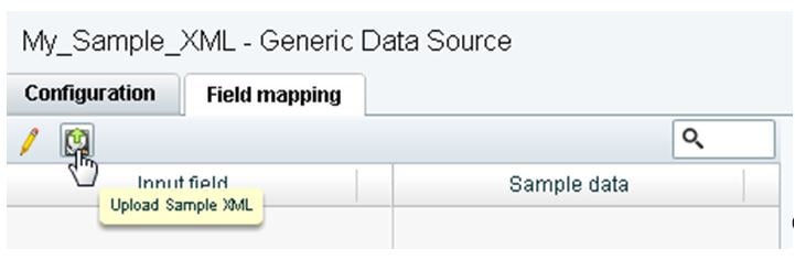
2.![]() To upload a sample XML file, complete the following steps:
To upload a sample XML file, complete the following steps:
a.![]() Click the upload arrow icon (Figure 31).
Click the upload arrow icon (Figure 31).
Figure 31 Upload Sample XML File for Generic Data Source Field Mapping
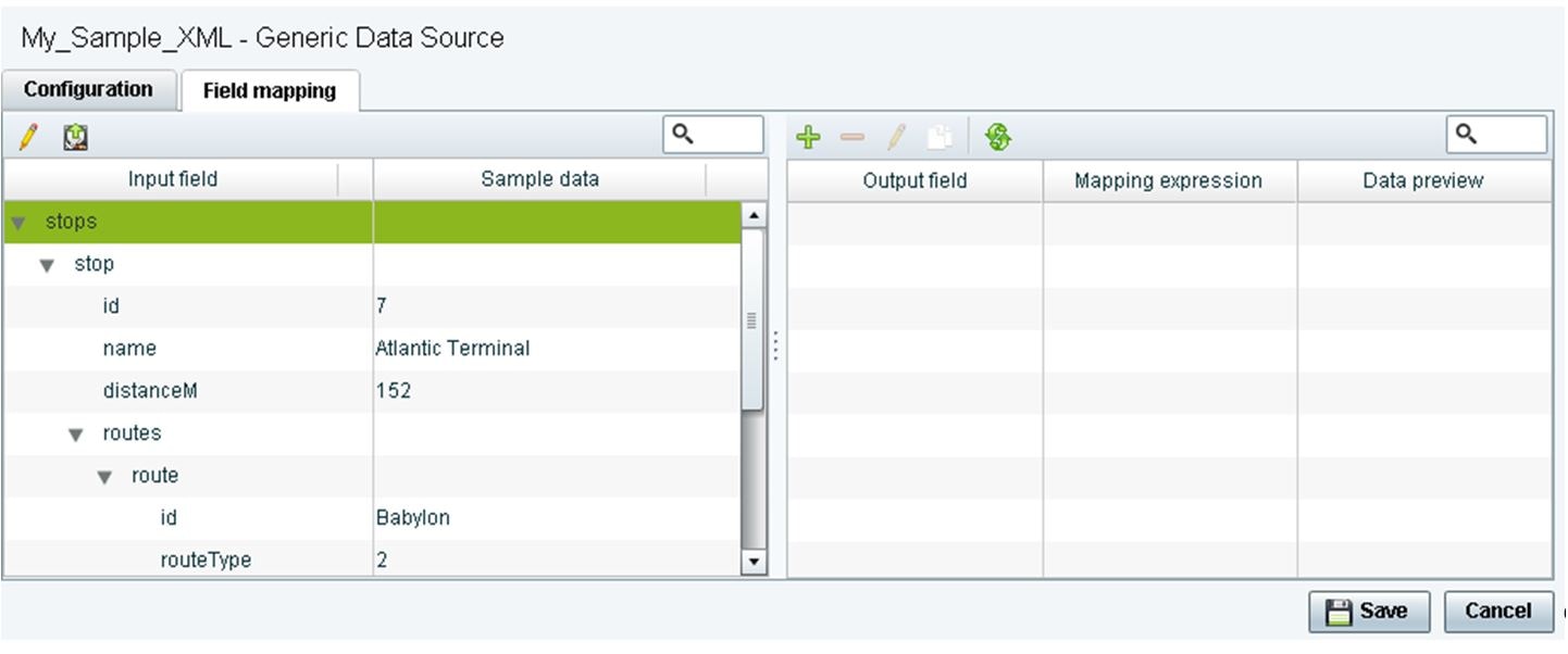
b.![]() In the Open dialog box, go to the location of your XML sample file and select it.
In the Open dialog box, go to the location of your XML sample file and select it.
The data fields from the XML file are listed in the Input field box (Figure 32). You can click the arrows to verify the available input fields and sample data that were uploaded.
Figure 32 Sample XML File Input Fields
Alternate Procedure
To provide sample XML data for generic data sources:
1.![]() Go to the Field Mapping screen for the selected generic data source.
Go to the Field Mapping screen for the selected generic data source.
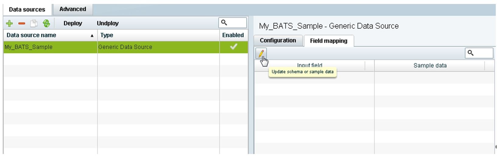
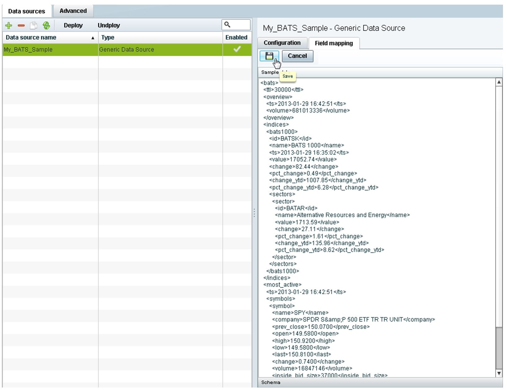
2.![]() To manually provide sample XML data, click the pencil icon (Figure 33).
To manually provide sample XML data, click the pencil icon (Figure 33).
Figure 33 Update Sample Data for Generic Data Source Field Mapping
3.![]() In the Sample data panel, paste the representative XML code from your sample file and click the Save icon.
In the Sample data panel, paste the representative XML code from your sample file and click the Save icon.
Figure 34 shows an excerpt of XML code from a source for BATS Exchange data.
Figure 34 Paste XML into Sample Data Panel
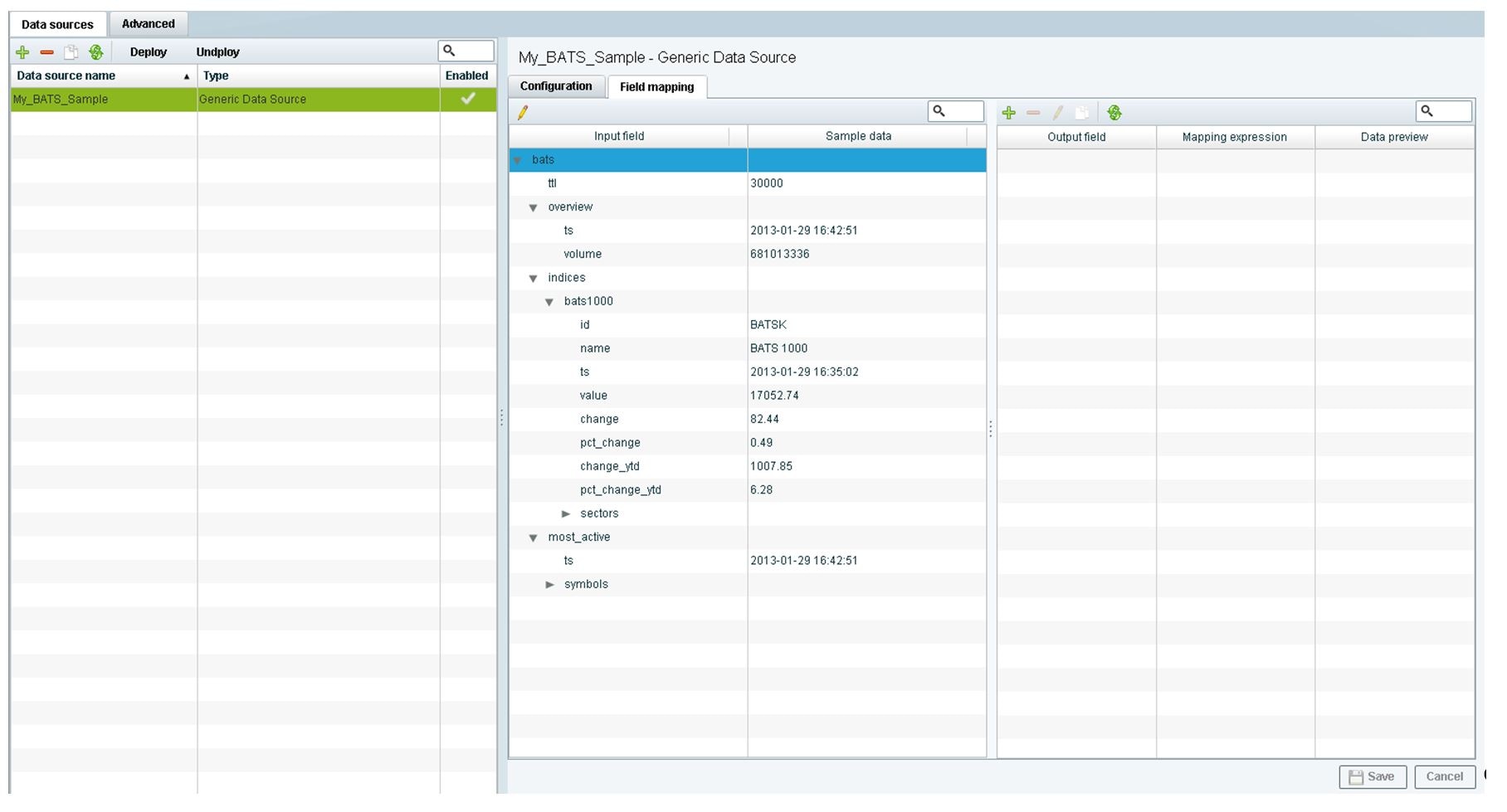
The input fields with sample data from the saved XML source that you pasted are shown in the Field Mapping screen. You can expand the fields to show more data elements (Figure 35).
Figure 35 Paste XML into Sample Data Panel
What To Do Next
Select the input statistics that you want to map for output display. For more information, see Selecting Input Statistics and Mapping to Output Fields for Display.
Selecting Input Statistics and Mapping to Output Fields for Display
To select input statistics and map to output fields for display:
1.![]() Go to the Field Mapping screen for the selected data source.
Go to the Field Mapping screen for the selected data source.
2.![]() To view the available statistics, click the arrow beside the data file name to expand the list.
To view the available statistics, click the arrow beside the data file name to expand the list.
The Sample Data column displays a representative value for each statistic.
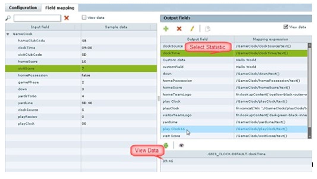
3.![]() With your mouse, select a statistic and drag-and-drop it to the Output Fields panel on the right (Figure 36).
With your mouse, select a statistic and drag-and-drop it to the Output Fields panel on the right (Figure 36).
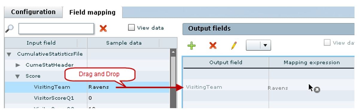
The Add Output field dialog box displays (Figure 37).
Figure 37 Add Output Field Dialog Box
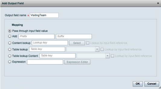
4.![]() Modify the Output field name or other mapping options as needed.
Modify the Output field name or other mapping options as needed.
For more information, see Modifying the Output Format of a Statistic.
5.![]() Continue to select and add statistics to the Output fields panel.
Continue to select and add statistics to the Output fields panel.
What To Do Next
Enable the data source. For more information, see Enabling the Data Source Configuration.
Enabling the Data Source Configuration
By default, external data collection and configuration is disabled. Once you have completed your configuration, you must both enable the data source and save the configuration to allow collection of the data.
Disabled data sources are indicated by a gray checkmark in the Enabled column of the corresponding data source name. When a data source is enabled, the checkmark turns green.
NOTE : Real-time data collection from the SIAB server will not begin until the External Content Integration application has been both enabled and restarted in Cisco Vision Director. For more information, see the Activating Data Integration System-Wide From the Management Dashboard and Restarting the Data Integration Application.
To enable the data source configuration:
1.![]() In the left pane, select the data source.
In the left pane, select the data source.
2.![]() Click Deploy. A message box appears asking you to restart the application.
Click Deploy. A message box appears asking you to restart the application.
3.![]() If you have completed all of the changes that you want to make on the Configuration tab, restart the application.
If you have completed all of the changes that you want to make on the Configuration tab, restart the application.
For more information, see the Restarting the Data Integration Application.
NOTE : To disable a data source configuration, repeat this task but click Undeploy at Step 2.
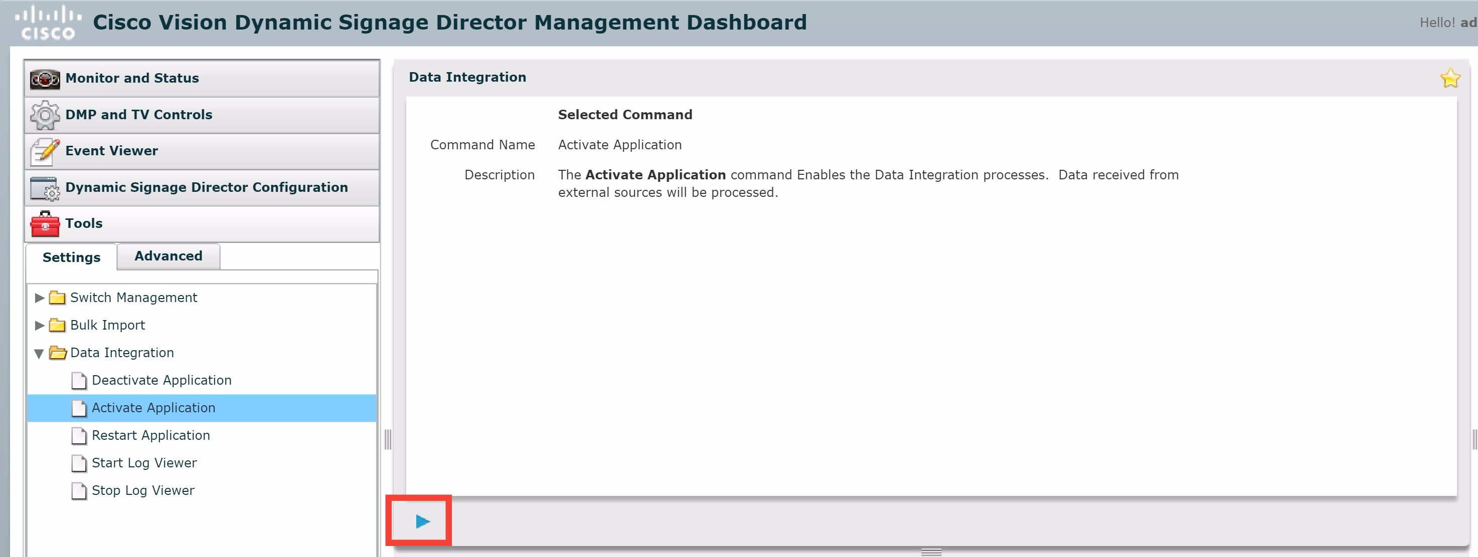
Activating Data Integration System-Wide From the Management Dashboard
By default, External Content Integration is disabled system-wide in Cisco Vision Director. After you have saved and enabled your data source configuration, you must activate the application and restart it from the Management Dashboard before data collection can begin.
If you disabled the Data Integration application, it must only be activated once to deploy it in the Cisco Vision Director server. Once the Data Integration application has been activated in the system, then any time the configuration has been changed, the application only must be restarted.
To activate Data Integration system-wide:
1.![]() Log into Cisco Vision Director as an Administrator.
Log into Cisco Vision Director as an Administrator.
2.![]() From the Cisco Vision Director Main Menu, click the Gear icon > Management Dashboard.
From the Cisco Vision Director Main Menu, click the Gear icon > Management Dashboard.
3.![]() Using the Management Dashboard drawers, go to Tools > Settings > Data Integration.
Using the Management Dashboard drawers, go to Tools > Settings > Data Integration.
4.![]() Select Activate Application.
Select Activate Application.
6.![]() When the confirmation message box appears, click OK to run the command.
When the confirmation message box appears, click OK to run the command.
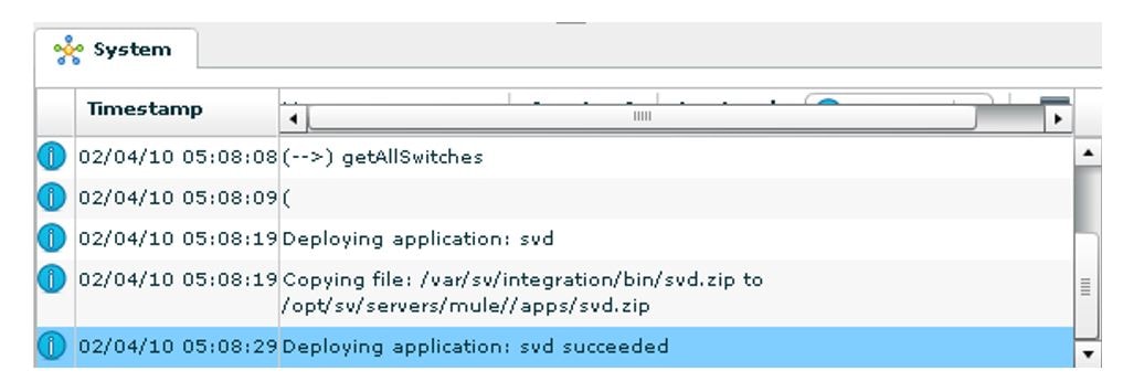
7.![]() To verify the application activation, look for the success message in the log display area of the screen.
To verify the application activation, look for the success message in the log display area of the screen.
Figure 38 Activate Application
8.![]() After the processing has completed, select Restart Application.
After the processing has completed, select Restart Application.
For more information, see the Restarting the Data Integration Application.
Restarting the Data Integration Application
Any time that you have made a change to the Data Integration settings on the Configuration tab for external data sources, you must restart the application from the Cisco Vision Director Management Dashboard.
When you save the configuration, a message displays as a reminder to restart:

NOTE : Changes to the data source field mapping only need to be saved, but the application does not have to be restarted. However, if for some reason you did not do a restart of the application after making changes in the Configuration tab before going on to save changes in Field mapping, then you also will see this message about the required restart at the time you save the Field mapping.
To restart the Data Integration Application:
1.![]() Log into Cisco Vision Director as an Administrator.
Log into Cisco Vision Director as an Administrator.
2.![]() From the Cisco Vision Director Main Menu, click the Gear icon > Management Dashboard.
From the Cisco Vision Director Main Menu, click the Gear icon > Management Dashboard.
3.![]() Using the Management Dashboard drawers, go to Tools > Settings > Data Integration.
Using the Management Dashboard drawers, go to Tools > Settings > Data Integration.
4.![]() Select Restart Application.
Select Restart Application.
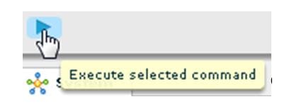
5.![]() Click the Play button to run the command.
Click the Play button to run the command.
6.![]() When the confirmation message box appears, click OK to run the command.
When the confirmation message box appears, click OK to run the command.
7.![]() To verify the application activation, look for the success message in the log display area of the screen.
To verify the application activation, look for the success message in the log display area of the screen.
Verifying the Integration
This section includes the following topics:
Verifying Receipt of Real-Time Data
Assuming that your network connection to the external data source is available and you have enabled the data source, real-time data is collected after you both activate and restart the application in the Management Dashboard.
To verify the receipt of real-time data:
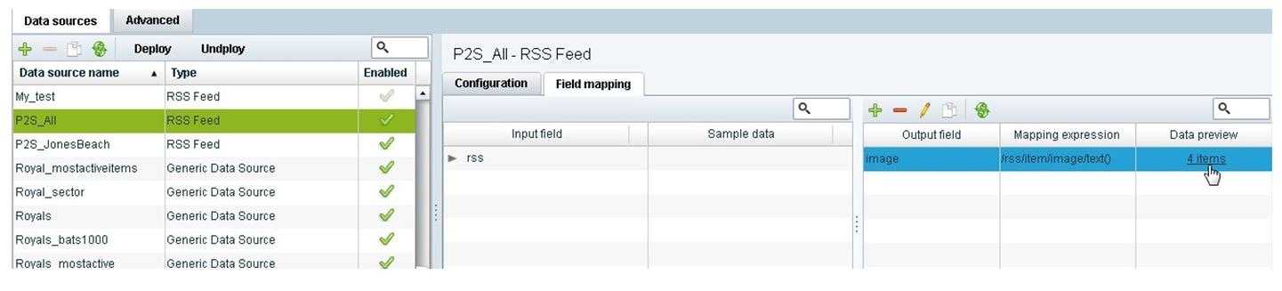
1.![]() From the Data Integration interface, select the data source that you want to verify.
From the Data Integration interface, select the data source that you want to verify.
3.![]() In the Output fields panel, select the link in the Data Preview column.
In the Output fields panel, select the link in the Data Preview column.
Figure 39 shows selection of a Mozes RSS feed with two image items available for data preview from the active feed.
Figure 39 Data Preview Example
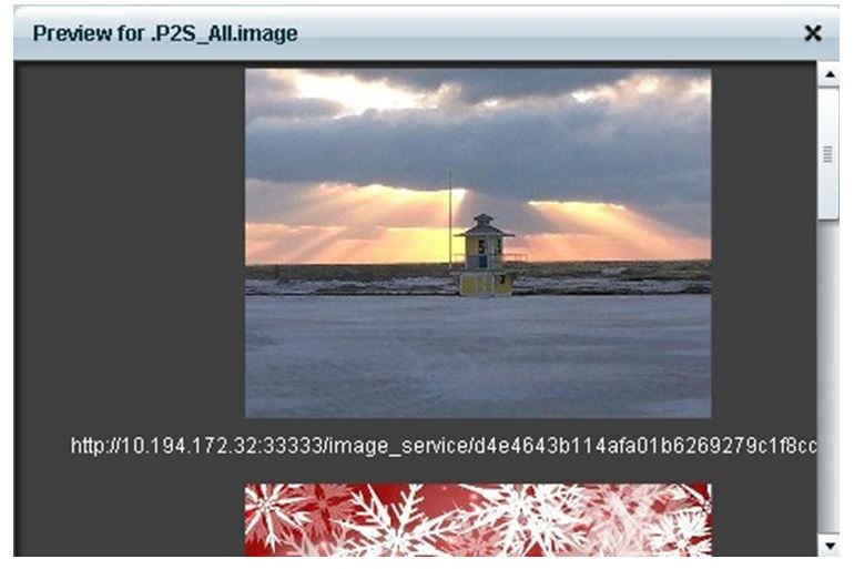
After you click the link, a Preview window opens displaying the live data from your feed.
Figure 40 shows an example of the images along with their corresponding URLs that are displayed in the preview window.
TIP : Use the scroll bar to see all the available preview data.
Figure 40 Image Preview of Active RSS Feed
Verifying the Integration Broker Service Status
To verify the integration broker service status:
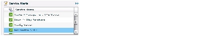
1.![]() From the Management Dashboard, go to the Service Alerts pane in the bottom right corner.
From the Management Dashboard, go to the Service Alerts pane in the bottom right corner.
2.![]() Navigate to find the Integration Broker service name and observe its status icon.
Navigate to find the Integration Broker service name and observe its status icon.
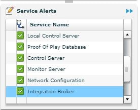
When the icon is green, the Data Integration service is successfully activated.
Figure 41 shows an example of real-time data for the NFL GSIS clockTime statistic.
Figure 41 Clock Time Real-Time Data Statistic
3.![]() Click the Refresh icon (Figure 42) and observe that the value is changing to confirm receipt of real-time data.
Click the Refresh icon (Figure 42) and observe that the value is changing to confirm receipt of real-time data.
Figure 42 Refresh Icon for Real-Time Data
Modifying the Default Data Throttling
The following data throttling options are provided in Cisco Vision Director:
■![]() Wait to read data from source (FTP polling interval)—NFL cumulative statistics only
Wait to read data from source (FTP polling interval)—NFL cumulative statistics only
Specifies how often (in milliseconds) to retrieve data from the SIAB server. The recommended value is 5000 ms (5 seconds).
■![]() Wait to push data to destination
Wait to push data to destination
Specifies the frequency with which the data is multicast to all DMPs in the Cisco Vision Director server. The recommended value is 5000 ms (5 seconds).
If there has not been any change in data since the last poll, then this throttle specifies the longest amount of time to wait before sending the multicast of unchanged data to all DMPs. The recommended value is 15000 ms (15 seconds).
1.![]() In the left pane, select the data source type.
In the left pane, select the data source type.
2.![]() Click the Configuration tab.
Click the Configuration tab.
The configuration for the selected data source appears in the right pane.
3.![]() In the Data throttling section, set one or more of the throttling values.
In the Data throttling section, set one or more of the throttling values.
Figure 43 shows a throttling configuration example for the NFL cumulative statistics data source.
Figure 43 NFL Cumulative Statistics Throttling Configuration Example
Figure 7 shows a throttling configuration example for the NFL clock UDP data source.
The same throttling options are available for the scoreboard controller UDP connection.
 Feedback