- About This Guide
- Getting Started with the Digital Media Player
- Planning the Digital Media Player Deployment
- Deploying the Digital Media Player
- Verifying the Deployment of the Digital Media Player
- Monitoring and Maintaining the Digital Media Player
- Troubleshooting the Digital Media Player
- Appendix A: Management Dashboard Commands for the Digital Media Player
- Appendix B: Display Parameters for the Digital Media Players
- Appendix C: Configuring an IOS DHCP Server to Support the Digital Media Players
Release 6.3: Cisco Vision Deployment Guide for Digital Media Players: Dynamic Signage Director
Bias-Free Language
The documentation set for this product strives to use bias-free language. For the purposes of this documentation set, bias-free is defined as language that does not imply discrimination based on age, disability, gender, racial identity, ethnic identity, sexual orientation, socioeconomic status, and intersectionality. Exceptions may be present in the documentation due to language that is hardcoded in the user interfaces of the product software, language used based on RFP documentation, or language that is used by a referenced third-party product. Learn more about how Cisco is using Inclusive Language.
- Updated:
- November 19, 2020
Chapter: Getting Started with the Digital Media Player
- Workflow Summary to Get Started
- Operating Environment for the Digital Media Players
- Physical Characteristics of the Digital Media Players
- Firmware Provisioning on the DMPs
- Auto-Provisioning on the Digital Media Players
- HDCP Support on the Digital Media Players
- IR Receiver for the Digital Media Players
- Storage and Memory on the Digital Media Players
- Synchronization on the Digital Media Players
- Switch Communication on the Digital Media Players
- WiFi Network Connectivity on the CV-UHD and SV-4K DMPs
Getting Started with the Digital Media Players
Series 2 DMPs: DMP-2K and SV-4K
Series 3 DMPs: CV-HD and CV-UHD
Series 4 DMPs: CV-HD2 and CV-UHD2
Note: Cisco announced an End Of Sale and support for the Series 2 DMPs, November 30, 2018.
This module provides a workflow summary with information about the Series 2, Series 3, and Series 4 hardware, software features, and key considerations before deploying these digital media players.
It is intended for anyone who is responsible for installing and configuring the digital media player and for anyone interested in understanding its general operation.
It includes the following topics:
■![]() Workflow Summary to Get Started
Workflow Summary to Get Started
■![]() Operating Environment for the Digital Media Players
Operating Environment for the Digital Media Players
■![]() Physical Characteristics of the Digital Media Players
Physical Characteristics of the Digital Media Players
■![]() IR Remote for Cisco Vision Dynamic Signage Director
IR Remote for Cisco Vision Dynamic Signage Director
■![]() Default Settings for the Digital Media Player
Default Settings for the Digital Media Player
■![]() Feature Summary for the Digital Media Player
Feature Summary for the Digital Media Player
■![]() Key Considerations for the Digital Media Players
Key Considerations for the Digital Media Players
■![]() Best Practices for DMP Deployment
Best Practices for DMP Deployment
Workflow Summary to Get Started
Table 1 provides a summary of the tasks and related information to get familiar with the digital media player.
Operating Environment for the Digital Media Players
Table 2 describes the supported environment for proper operation of the Series 2, Series 3, and Series 4 media players.
Caution : Do not allow condensation of any vapor to touch the DMPs at any time. Do not spill food or drinks of any kind on the DMPs. Before powering up the DMP, let it come to room temperature to remove any possibility of condensation build up inside the device.
Physical Characteristics of the Digital Media Players
This section provides information about the dimensions and ports on each of the Series 2, Series 3, and Series 4 media players:
■![]() Cabling Information for the Digital Media Player
Cabling Information for the Digital Media Player
■![]() Mounting Guidelines for the Digital Media Players
Mounting Guidelines for the Digital Media Players
■![]() LEDs on the Digital Media Players
LEDs on the Digital Media Players
Note: Refer to the DMP-specific Datasheet for additional specification information. See Datasheets for Cisco Vision Digital Media Players.
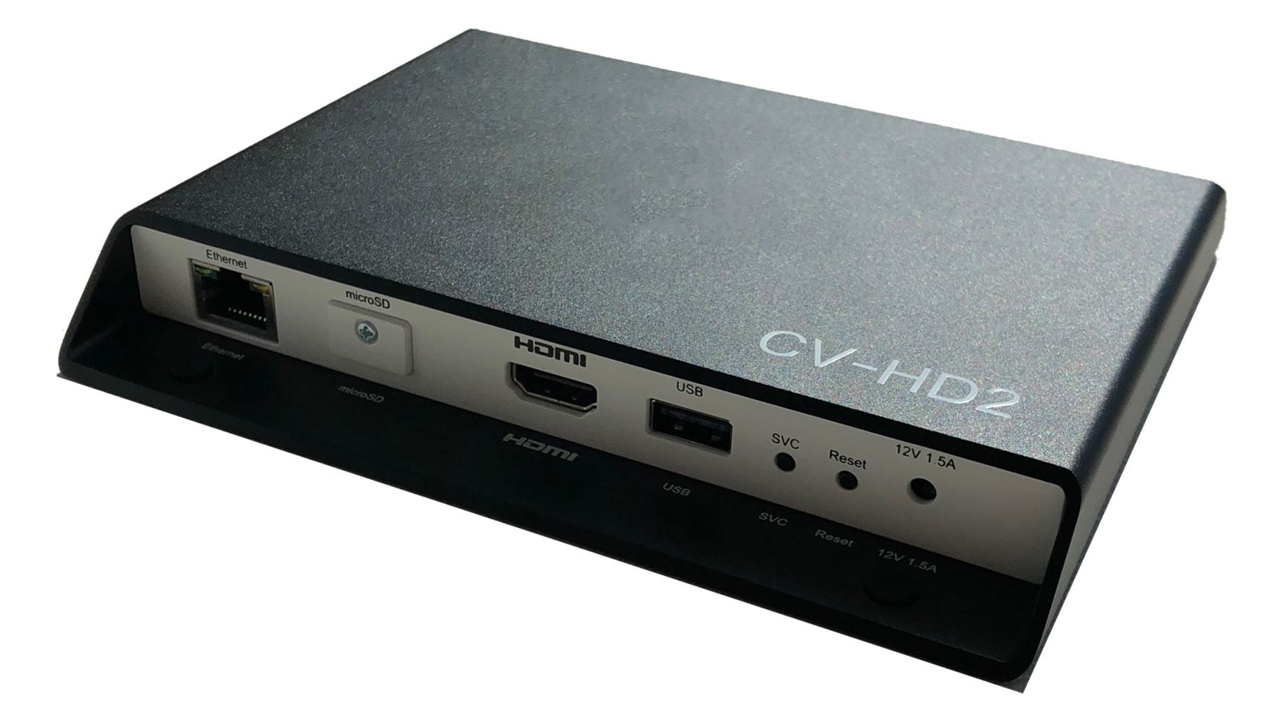
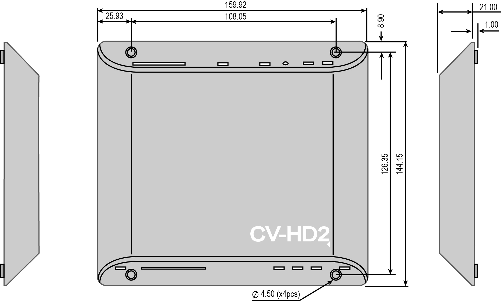
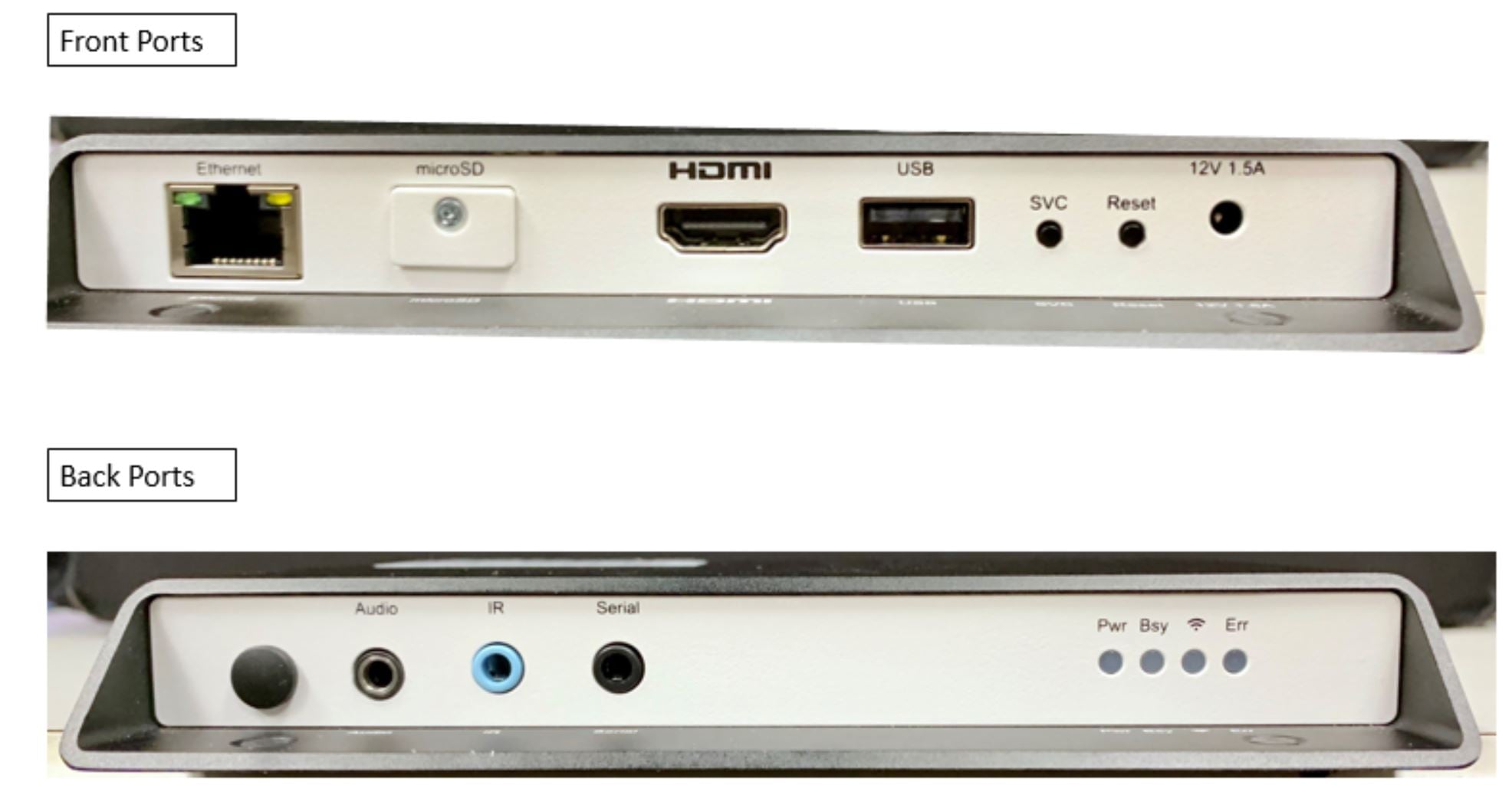
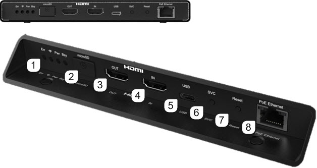
CV-HD2 Media Player
Dimensions of the CV-HD2 Media Player
Ports of the CV-HD2 Media Player
|
|
|
|---|---|
Displays when the board is powered up and not in reset mode. Flashes during the firmware update process. |
|
Flashes any time there is file-system activity (on any storage device) |
|
Flashes when the player is connecting to the wireless network. Displays when connected. |
|
Flashes a certain number of times to indicate which error is occurring. For ERR codes, see Table 22. |
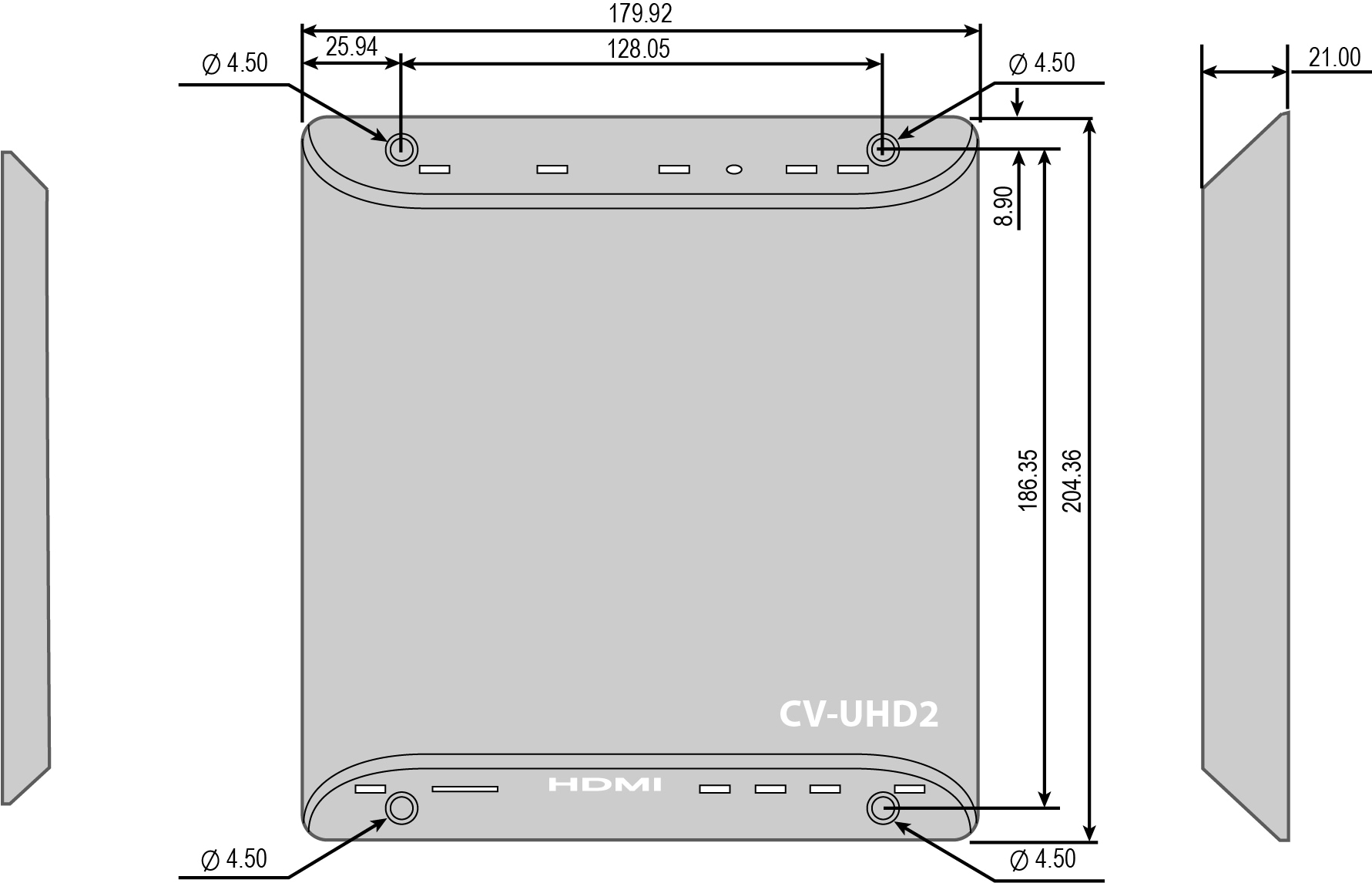
CV-UHD2 Media Player

Dimensions of the CV-UHD2 Media Player
Ports of the CV-UHD2 Media Player
|
|
|
|---|---|
Displays when the board is powered up and not in reset mode. Flashes during the firmware update process. |
|
Flashes any time there is file-system activity (on any storage device) |
|
Flashes when the player is connecting to the wireless network. Displays when connected. |
|
Flashes a certain number of times to indicate which error is occurring. See Table 22 for flash codes described. |
|
|
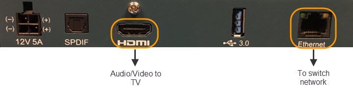
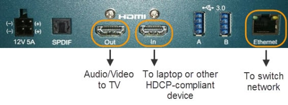
High-Definition Multimedia Interface (HDMI) output connector (compatible with HDMI 2.0 devices) to transmit digital audio/video content. |
|
|
The signaling conforms with DVI 1.0, HDMI 1.4, and HDCP 2.2 standards. |
|
The Service (SVC) button provides a dedicated GPIO button (GPIO12) for the OS. Pressing the SVC button pulls the pin low. Conversely, releasing the button pulls the pin high. |
|
The Reset button is connected to the reset circuit. Pressing down the Reset button will send an initial signal to the system software, and holding the reset button low for approximately 4 seconds will cause a hard reset. |
|
|
|
Note: WiFi is not supported for this DMP.
Warning : Do not supply power to network port using AC power cable. When using PoE, budget appropriate power
(30 W) for optimal DMP operation and use LLDP.
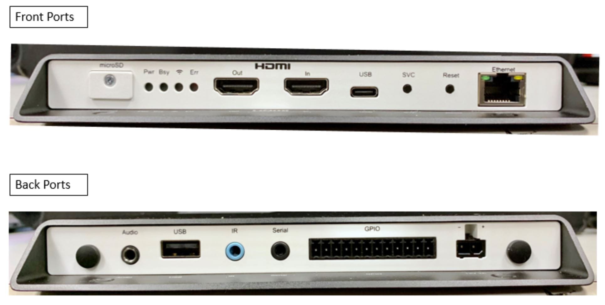
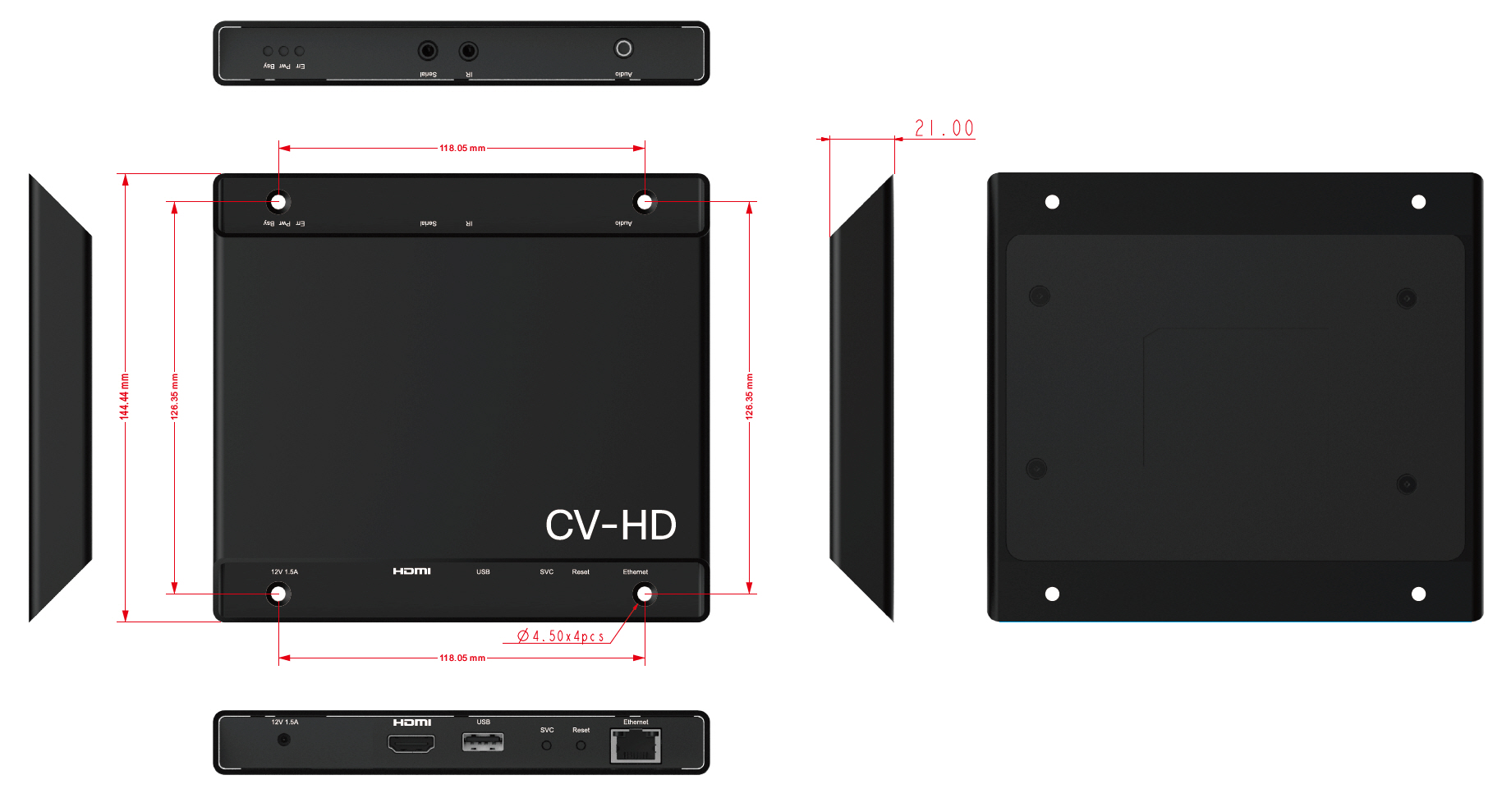
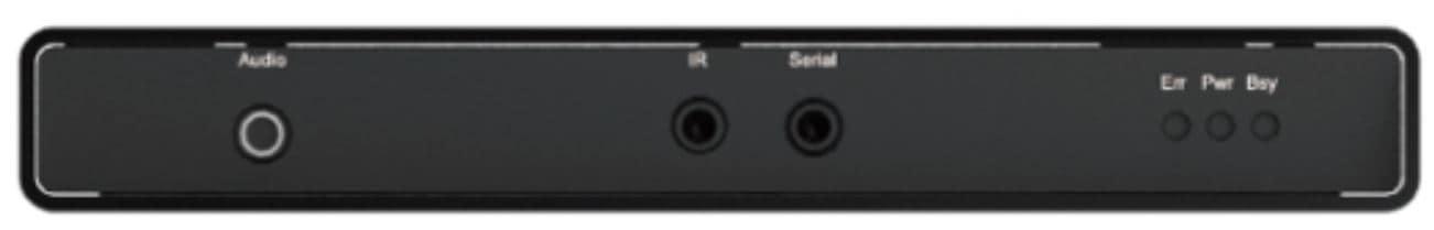
CV-HD Media Player
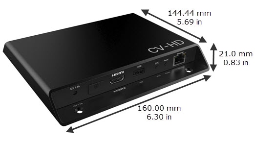
Dimensions of the CV-HD Media Player
Ports of the CV-HD Media Player
Figure 9 Front Ports of CV-HD Media Player
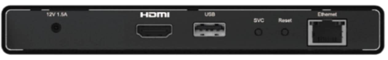
Figure 10 Rear Ports of CV-HD Media Player
|
|
|
|---|---|
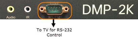
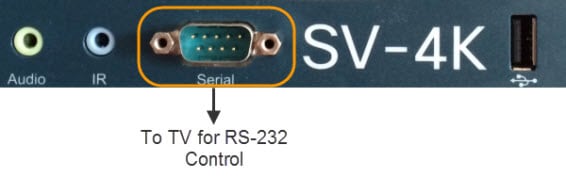
Connect to TV serial port for control of the TV via RS-232 commands. |
|
Flashes a certain number of times to indicate which error is occurring. See Table 21 for flash codes described. |
|
(green)—Displays when the device is powered on and not in reset mode. |
|
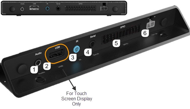
CV-UHD Media Player
Dimensions of the CV-UHD Media Player
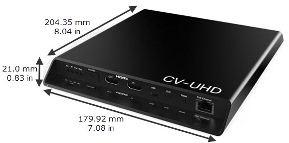
Ports on the CV-UHD Media Player
|
|
Also supports a “Mini Toslink” connector which outputs digital audio. 3.5 mm audio out (optical digital and analog). |
|
Intended for touch screen display use only with Cisco Vision Dynamic Signage Director. |
||
|
|
|
|
Serial (TTL)2 |
Connect to TV serial port for control of the TV via RS-232 commands. |
|
|
|
||
The CV-UHD is qualified for Cisco Vision Dynamic Signage Director using Power over Ethernet (PoE+) via the Ethernet port3. |
DMP-2K Media Player
Dimensions of the DMP-2K Media Player
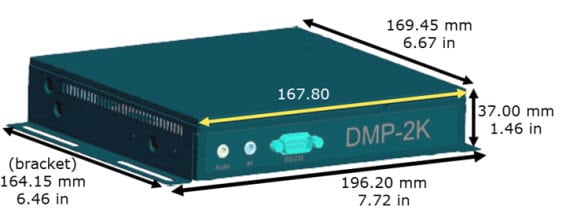
Ports on the DMP-2K Media Player
|
|
|
|
|---|---|---|
|
|
|
|
|
|
|
|
|
|
|
|
SV-4K Media Player
Dimensions of the SV-4K Media Player
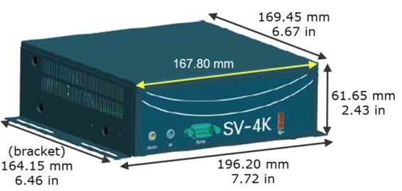
Ports on the SV-4K Media Player
|
|
|
|
|---|---|---|
|
|
|
|
|
|
|
|
|
|
|
|
|
|
|
|
|
|
|
|
|---|---|---|
|
|
Note: The SV-4K must first be provisioned over PoE+ with configuration of WiFi completed in Cisco Vision Dynamic Signage Director. See How to Deploy WiFi Network Connectivity on the SV-4K. |
|
|
|
|
|
|
|
|
|
|
|
|
|
|
USB 3.0 B |
|
|
|
|
|
|
Warning : Do not supply power to network port using AC power cable. When using PoE, budget appropriate power
(30 W) for optimal DMP operation and use LLDP.
Cabling Information for the Digital Media Player
Table 15 describes the cables that ship with the DMP-2K and SV-4K hardware.
Table 16 describes the cables that ship with the CV-HD and CV-UHD hardware.
Table 17 describes the cables that ship with the CV-HD2 and CV-UHD2 hardware.
Other Cabling Considerations
Assess the ports available on the TVs at the venue so that you can get any additional adapters or cable types that are needed to connect the Series 2, Series 3, and Series 4 DMPs to the TVs. RX and TX pins vary for each TV manufacturer and a null modem adapter may be required. We do not recommend using RS232 splitters to control multiple TVs. Best practice is a 1:1 DMP to TV mapping. For HDMI, no splitters are qualified.
Ethernet Cable
Use standard Category 5e or 6 cables no longer than 100 meters in length.
Null Modem (Crossover) Cable
The Series 2 DMPs are a DTE serial device. Therefore, if the TV also has a DTE (male) serial port, use a null modem (crossover) cable for the TV control connection.
HDMI-to-DVI Adapter
If the TV does not support HDMI In, then you cannot use the standard HDMI-to-HDMI cable that ships with the DMPs. However, if the TV supports a DVI-D connection, then you can acquire a DVI adapter for the HDMI cable to make the HDMI-to-DVI connection.
Since this type of connection only supports video, you will also need to connect the DMP audio port to the audio input ports on the TV if audio support is required.
Other HDMI Cable Adapters
The HDMI cable that ships with the digital media player is compliant with HDMI version 1.4. If you are using any other cable adapters, be sure that they support HDMI version 1.4 if you plan to support UHD video content.
Audio Cables
Audio cables are not generally needed. However, there are a couple of cases where you might need to make an audio connection to the SV-4K:
■![]() If you need to support an HDMI-to-DVI connection from the SV-4K to the TV since this supports video only.
If you need to support an HDMI-to-DVI connection from the SV-4K to the TV since this supports video only.
■![]() If you need to connect to external audio distribution equipment when audio is to be distributed within an area.
If you need to connect to external audio distribution equipment when audio is to be distributed within an area.
RS-232 Serial Pinout for the Series 2 DMP
Table 18 provides the pin out for the DE-9 serial connector on the front panel of the Series 2 DMPs.
Mounting Guidelines for the Digital Media Players
■![]() Guidelines for Mounting the Series 2 Media Player
Guidelines for Mounting the Series 2 Media Player
Guidelines for Mounting the Series 2 Media Player
Consider the following guidelines before mounting the Series 2 media player:
■![]() Do not fit in Sunbrite cases.
Do not fit in Sunbrite cases.
■![]() Full dimensions (width / height / depth) with mounting brackets:
Full dimensions (width / height / depth) with mounting brackets:
–![]() 196.20 mm / 37.00 mm / 169.45 mm
196.20 mm / 37.00 mm / 169.45 mm
–![]() 196.20 mm / 61.65 mm / 169.45 mm
196.20 mm / 61.65 mm / 169.45 mm
–![]() The bracket length is 164.15 mm / 6.46 in.
The bracket length is 164.15 mm / 6.46 in.
–![]() DMP-2K: 1 lb 14 oz / 850.5 grams
DMP-2K: 1 lb 14 oz / 850.5 grams
–![]() SV-4K: 2 lb 4 oz / 1020.6 grams
SV-4K: 2 lb 4 oz / 1020.6 grams
■![]() Attach to the wall using the brackets on each side of the device using 4 screws (one for each bracket slot) that measure between 3.5 mm and 4.2 mm in diameter.
Attach to the wall using the brackets on each side of the device using 4 screws (one for each bracket slot) that measure between 3.5 mm and 4.2 mm in diameter.
■![]() Do not block the right side panel so that you can see the LEDs for troubleshooting.
Do not block the right side panel so that you can see the LEDs for troubleshooting.
■![]() Ensure all air vents are clear for proper cooling.
Ensure all air vents are clear for proper cooling.
■![]() Choose a location that works with the required IR extender cable for infrared support. No IR receptor is built into the DMP.
Choose a location that works with the required IR extender cable for infrared support. No IR receptor is built into the DMP.
Caution : Do not mount the DMP near where HVAC outlets or ducts may drip condensed air onto the device. Humid conditions are not recommended and may cause the unit to fail or behave unpredictably.
Note: The tested range is about 20 ft. To achieve this range, position the receiver facing outward. The receiver is enclosed and not visible.
Guidelines for Mounting the Series 3 Media Players
Consider the following guidelines before mounting a Series 3 media player:
■![]() Full dimensions (width / height / depth) with mounting brackets:
Full dimensions (width / height / depth) with mounting brackets:
–![]() 160.00 mm / 21.00 mm / 144.44 mm
160.00 mm / 21.00 mm / 144.44 mm
–![]() The mounting holes are inset 20.98 mm (0.82 in) from the box edge.
The mounting holes are inset 20.98 mm (0.82 in) from the box edge.
–![]() 204.35 mm / 21.00 mm / 179.92 mm
204.35 mm / 21.00 mm / 179.92 mm
–![]() The mounting holes are inset 30.94 mm (1.22 in) from the box edge.
The mounting holes are inset 30.94 mm (1.22 in) from the box edge.
–![]() CV-UHD: 1 lb 4 oz / 567 grams
CV-UHD: 1 lb 4 oz / 567 grams
■![]() Attach to the wall using the mounting holes on the front and back with 4 screws (one for each hole) that measure between 3.5 mm and 4.2 mm in diameter.
Attach to the wall using the mounting holes on the front and back with 4 screws (one for each hole) that measure between 3.5 mm and 4.2 mm in diameter.
■![]() Ensure all air vents are clear for proper cooling.
Ensure all air vents are clear for proper cooling.
■![]() Choose a location that works with the required IR extender cable for infrared support. No IR receptor is built into the DMP.
Choose a location that works with the required IR extender cable for infrared support. No IR receptor is built into the DMP.
Caution : Do not mount the DMP near where HVAC outlets or ducts may drip condensed air onto the device. Humid conditions are not recommended and may cause the unit to fail or behave unpredictably.
Note: The tested range is about 20 ft. To achieve this range, position the receiver facing outward. The receiver is enclosed and not visible.
Guidelines for Mounting the Series 4 Media Players
Consider the following guidelines before mounting a Series 4 media player:
■![]() Full dimensions (width / height / depth) with mounting brackets:
Full dimensions (width / height / depth) with mounting brackets:
–![]() 159.92 mm / 21.00 mm / 144.15 mm
159.92 mm / 21.00 mm / 144.15 mm
–![]() The mounting holes are inset 25.93 mm (1.02 in) from the box edge.
The mounting holes are inset 25.93 mm (1.02 in) from the box edge.
–![]() 179.92 mm / 21.00 mm / 204.36 mm
179.92 mm / 21.00 mm / 204.36 mm
–![]() The mounting holes are inset 25.94 mm (1.02 in) from the box edge.
The mounting holes are inset 25.94 mm (1.02 in) from the box edge.
–![]() CV-UHD2: 1 lb 4 oz / 567 grams
CV-UHD2: 1 lb 4 oz / 567 grams
■![]() Attach to the wall using the mounting holes on the front and back with 4 screws (one for each hole) that measure between 3.5 mm and 4.2 mm in diameter.
Attach to the wall using the mounting holes on the front and back with 4 screws (one for each hole) that measure between 3.5 mm and 4.2 mm in diameter.
■![]() Ensure all air vents are clear for proper cooling.
Ensure all air vents are clear for proper cooling.
■![]() Choose a location that works with the required IR extender cable for infrared support. No IR receptor is built into the DMP.
Choose a location that works with the required IR extender cable for infrared support. No IR receptor is built into the DMP.
Caution : Do not mount the DMP near where HVAC outlets or ducts may drip condensed air onto the device. Humid conditions are not recommended and may cause the unit to fail or behave unpredictably.
Note: The tested range is about 20 ft. To achieve this range, position the receiver facing outward. The receiver is enclosed and not visible.
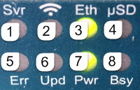
LEDs on the Digital Media Players
LEDs on the Series 2 Media Players
The Series 2 media players have 8 LEDs in two banks of 4 on the right panel of the device. Figure 20 shows normal operation for the device on a Cisco Vision Dynamic Signage Director network.
Note: Some of the LEDs apply to hardware features that are not enabled for use with Cisco Vision Dynamic Signage Director.
Figure 20 Series 2 Media Player LED Bank
|
|
|
|
|
|
|
|
|
|
|
|
|
|
|
|
|
|
|
|
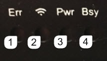
LEDs on the Series 3 Media Players
The Series 3 media players have one row of LEDs on the left front panel of the device. The CV-UHD media player has an extra LED for WiFi support (Figure 21).
|
|
|
|
|
|
|
|
|
|
LEDs on the Series 4 Media Players
The Series 4 digital media players have one row of LEDs on the front panel of the device.
IR Remote for Cisco Vision Dynamic Signage Director
All media players use the same IR Remote device shown in Figure 22. Generally, the IR Remote is used for TV control. However, even if you are not using the IR Remote for TV control, it is important to realize that the IR Remote also allows you to get information to troubleshoot the media player.
Note: The IR Remote is not automatically shipped with the Cisco Vision Dynamic Signage Director media players and must be ordered separately. To order an IR Remote control device, please contact your Cisco Sales Representative for available IR Remote solutions.
Figure 22 shows the description for each of the buttons on the Cisco Vision Dynamic Signage Director IR Remote.
Figure 22 Cisco Vision Dynamic Signage Director IR Remote Button Descriptions
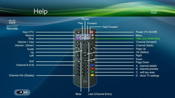
IR Remote Sensor and IR Extender
Unlike for the Cisco DMP 4310G, the Series 2, Series 3, and Series 4 digital media players do not have their own IR receiver. An IR extender is required. For more information, see Mounting Guidelines for the Digital Media Players.
The IR remote also is a critical troubleshooting tool so it is important to ensure that all media players can be IR-controlled even if it is not needed during normal operation. For more information about the IR-Remote, contact your Cisco Sales Representative for available IR Remote solutions.
Default Settings for the Digital Media Player
The devices ship from the factory with certain default settings. Upon running the start-up sequence and in communication with Cisco Vision Dynamic Signage Director, the Series 2, Series 3, and Series 4 default settings are changed.
RS-232 Default Settings on the DMPs
After processing the HTML run-time module from Cisco Vision Dynamic Signage Director, the DMP is set to the following RS-232 default settings:
Note: The DMPs use default settings that match most TVs.
■![]() Baud—9600 (factory default is 115200)
Baud—9600 (factory default is 115200)
■![]() Flow Control—None (factory default is hardware flow control only)
Flow Control—None (factory default is hardware flow control only)
For information about the new RS-232 commands for the DMPs, see Appendix B: Display Parameters for the Digital Media Players.
Other Default Settings
By default, the following functionality is disabled on the Series 2, Series 3, and Series 4 media player:
Feature Summary for the Digital Media Player
This section includes the following topics:
■![]() Cisco Vision Dynamic Signage Director Software Feature Map for the DMPs
Cisco Vision Dynamic Signage Director Software Feature Map for the DMPs
■![]() Unsupported DMP Hardware Features
Unsupported DMP Hardware Features
Cisco Vision Dynamic Signage Director Software Feature Map for the DMPs
The following table identifies a subset of features that are supported only by certain DMP models in Cisco Vision Dynamic Signage Director.
Dual Video1with Luma Key |
||||||
Video Streamed to a Local HDMI-In Channel (HDMI-In Pass-Through)3 |
||||||
|
|
||||||
The following table identifies the globally-supported features for all media players in the release.
Unsupported DMP Hardware Features
The following DMP hardware features are not supported:
■![]() SD (and microSD, included with CV-HD2 only, as a factory-installed component)
SD (and microSD, included with CV-HD2 only, as a factory-installed component)
■![]() USB (3.0)—only used to connect HID-compliant touchscreen devices
USB (3.0)—only used to connect HID-compliant touchscreen devices
Note: The DMPs do not support content import and/or playback using the SD card or USB ports.
Key Considerations for the Digital Media Players
When you deploy a digital media player, there are several things that you should know about its operation. This section highlights some of the important differences to be aware of when deploying the digital media players.
This section includes the following topics:
■![]() Firmware Provisioning on the DMPs
Firmware Provisioning on the DMPs
■![]() Auto-Provisioning on the Digital Media Players
Auto-Provisioning on the Digital Media Players
■![]() HDCP Support on the Digital Media Players
HDCP Support on the Digital Media Players
■![]() IR Receiver for the Digital Media Players
IR Receiver for the Digital Media Players
■![]() Storage and Memory on the Digital Media Players
Storage and Memory on the Digital Media Players
■![]() Synchronization on the Digital Media Players
Synchronization on the Digital Media Players
■![]() Switch Communication on the Digital Media Players
Switch Communication on the Digital Media Players
■![]() WiFi Network Connectivity on the CV-UHD and SV-4K DMPs
WiFi Network Connectivity on the CV-UHD and SV-4K DMPs
Firmware Provisioning on the DMPs
The DMP firmware upgrade cannot be manually launched in the Configuration > System Configuration DMP command. It is done automatically when the device boots.
Caution: Before you power on the Series 2, Series 3, and Series 4 device for the first time, complete the following configuration and tasks:
For initial deployment of a DMP, verify:
–![]() No other accessories are attached to the DMP.
No other accessories are attached to the DMP.
–![]() Use standard Category 5e or 6 cables up to 100 m in length.
Use standard Category 5e or 6 cables up to 100 m in length.
■![]() Switch configuration, including the required LLDP for proper PoE+ operation. LLDP and POE+ not required for CV-HD/CV-HD2 players.
Switch configuration, including the required LLDP for proper PoE+ operation. LLDP and POE+ not required for CV-HD/CV-HD2 players.
■![]() DHCP server configuration, including the proper option 43 string.
DHCP server configuration, including the proper option 43 string.
■![]() Firmware upload for your Cisco Vision Dynamic Signage Director release.
Firmware upload for your Cisco Vision Dynamic Signage Director release.
■![]() Auto-registration settings for the DMP to properly provision its firmware.
Auto-registration settings for the DMP to properly provision its firmware.
Table 25 provides a summary of the firmware provisioning tasks for the DMP in the System Configuration > Configuration.
Auto-Provisioning on the Digital Media Players
■![]() The digital media players are automatically provisioned with global configuration settings from Cisco Vision Dynamic Signage Director.
The digital media players are automatically provisioned with global configuration settings from Cisco Vision Dynamic Signage Director.
■![]() As part of the start-up sequence, the device retrieves the Cisco Vision Dynamic Signage Director configuration, which includes all of the global settings for the devices, such as NTP configuration, jitter settings, and so on.
As part of the start-up sequence, the device retrieves the Cisco Vision Dynamic Signage Director configuration, which includes all of the global settings for the devices, such as NTP configuration, jitter settings, and so on.
To configure DMP global settings:
Click Configuration > System Configuration > Global DMP Settings.
To configure DMP auto-registration settings:
Click Configuration > System Configuration > Auto Registration Settings.
■![]() The DMP configuration in Cisco Vision Dynamic Signage Director is provisioned each time that the device boots.
The DMP configuration in Cisco Vision Dynamic Signage Director is provisioned each time that the device boots.
Caution: When running Cisco Vision Dynamic Signage Director on a virtual server, reference a reliable NTP server. NTP for Cisco Vision Dynamic Signage Director is configured using the TUI. For more information, see Cisco Vision Administration Guide: Dynamic Signage Director Release 6.3.
HDCP Support on the Digital Media Players
The DMPs natively support content that uses Intel's High-bandwidth Digital Content Protection (HDCP) through the installation of a protection key on the digital media player.
■![]() From the HDMI Out port, the DMPs support HDCP versions 1.4.
From the HDMI Out port, the DMPs support HDCP versions 1.4.
■![]() From the HDMI In port, the SV-4K, CV-UHD, and CV-UHD2 can receive HDCP 1.4.
From the HDMI In port, the SV-4K, CV-UHD, and CV-UHD2 can receive HDCP 1.4.
IR Receiver for the Digital Media Players
There is not an embedded IR receiver on the digital media players. Use the IR extender cable to use the IR Remote.
Storage and Memory on the Digital Media Players
The DMP devices have different sizes of solid-state storage and RAM (Table 26):
|
|
|
|
|---|---|---|
|
|
|
|
|
|
|
|
|
|
|
|
|
|
|
|
|
|
|
|
|
|
|
|
Note: The amount of RAM can make a difference in how the same content might play on different media player models. This difference might more likely be seen when playing HTML pass-through (URL) content.
To find information about available storage:
1.![]() Click Device Management > All Devices.
Click Device Management > All Devices.
3.![]() In the Status tab, go to Status Details or Utilization.
In the Status tab, go to Status Details or Utilization.
Note: The amount of available storage shown in Device Management reflects the total amount of space available on the SSD, not the actual storage pool available for content.
You also can find information about available storage if you view Device Details by clicking a screen from thumbnail view in Device Management (CCM).
Synchronization on the Digital Media Players
The digital media players support synchronization of content played among a group of devices using the Network Time Protocol (NTP) and Precision Time Protocol (PTP). NTP and PTP settings are provisioned globally for all digital media players.
The Cisco Vision Dynamic Signage Director server is provisioned as the default NTP source for all media players. When PTP is configured, only the PTP leader derives its clock using NTP.
Caution: When running Cisco Vision Dynamic Signage Director on a virtual server, reference a reliable NTP server. NTP for Cisco Vision Dynamic Signage Director is configured using the TUI. For more information, see Cisco Vision Administration Guide: Dynamic Signage Director Release 6.3 .
Switch Communication on the Digital Media Players
The digital media players communicate with the Cisco Connected Stadium switch using the required Link Layer Discovery Protocol (LLDP) rather than MediaNet. The media player determines available power (when using PoE+) over LLDP.
WiFi Network Connectivity on the CV-UHD and SV-4K DMPs
Wireless network connectivity to the CV-UHD or SV-4K is supported over an 802.11a, 802.11b, or 802.11n wireless network in the Cisco Vision Dynamic Signage Director venue.
Note: For initial deployment of a DMP with WiFi connectivity, you will need both a PoE+ network connection in addition to connection of the CV-UHD or SV-4K using the DMP power supply adapter. After the DMP is deployed for WiFi, a PoE+ connection is no longer needed for the DMP. In fact, the DMP will not route packets over the WiFi connection while the Ethernet port is connected and operational.
The wireless network SSID and passphrase is configured globally for all wireless devices in the system. The DMP firmware automatically tries to connect with WEP (if the passphrase is of a suitable length), WPA1 or WPA2.
For configuration information, see How to Deploy WiFi Network Connectivity on the SV-4K.
Multicast video is not supported due to bandwidth limitations over a wireless network.
For non-video control for the DMPs, one of these two options must be valid:
–![]() The wireless network must support multicast traffic for communication over the Cisco Vision Dynamic Signage Director network.
The wireless network must support multicast traffic for communication over the Cisco Vision Dynamic Signage Director network.
–![]() The DMPs must be configured to use the new Unicast Deployment functionality.
The DMPs must be configured to use the new Unicast Deployment functionality.
Best Practices for DMP Deployment
Using Bar Code Scanners and TV Labels at Installation Time
Note: This practice requires that you have already defined your Location names in Cisco Vision Dynamic Signage Director.
To increase the speed and accuracy of media player deployment:
■![]() Prepare TV labels with the Cisco Vision Dynamic Signage Director Location name in bar code format.
Prepare TV labels with the Cisco Vision Dynamic Signage Director Location name in bar code format.
■![]() Obtain a bar code scanner to record the Location bar code and MAC address from the media player.
Obtain a bar code scanner to record the Location bar code and MAC address from the media player.
■![]() Use the Cisco Vision Director Bulk Administration Tool (BAT) to upload data to Cisco Vision Dynamic Signage Director.
Use the Cisco Vision Director Bulk Administration Tool (BAT) to upload data to Cisco Vision Dynamic Signage Director.
Installer Workflow Example
To use a bar code scanner with TV labels:
1.![]() Mount the TV and media player.
Mount the TV and media player.
2.![]() Connect the TV and media player cables.
Connect the TV and media player cables.
3.![]() Attach a pre-printed label to TV.
Attach a pre-printed label to TV.
4.![]() Scan the Location bar code on the TV.
Scan the Location bar code on the TV.
5.![]() Scan the MAC address bar code on the media player.
Scan the MAC address bar code on the media player.
6.![]() Provide scanner to the supervisor or network administrator who downloads the data and formats it to be compatible with the Cisco Vision Dynamic Signage Director BAT TSV format.
Provide scanner to the supervisor or network administrator who downloads the data and formats it to be compatible with the Cisco Vision Dynamic Signage Director BAT TSV format.
7.![]() For more information, see the Cisco Vision Director Bulk Administration Tool guide.
For more information, see the Cisco Vision Director Bulk Administration Tool guide.
 Feedback