Release 5.0: Cisco Vision Administration Guide: Dynamic Signage Director (StadiumVision Director)
Bias-Free Language
The documentation set for this product strives to use bias-free language. For the purposes of this documentation set, bias-free is defined as language that does not imply discrimination based on age, disability, gender, racial identity, ethnic identity, sexual orientation, socioeconomic status, and intersectionality. Exceptions may be present in the documentation due to language that is hardcoded in the user interfaces of the product software, language used based on RFP documentation, or language that is used by a referenced third-party product. Learn more about how Cisco is using Inclusive Language.
- Updated:
- November 29, 2016
Chapter: Configuring the Cisco Vision Dynamic Signage Director Server System Settings
- Contents
- Prerequisites for Configuring Cisco Vision Dynamic Signage Director Server System Settings
- How to Configure Cisco Vision Dynamic Signage Director Server System Settings
- Completing Initial Configuration of System Settings After a Full ISO Installation
- Configuring the Cisco Vision Dynamic Signage Director Server Network Interface
- Editing the Hosts File
- Restarting the Network Service on the Server
- Generating the SSL Certificate
- Configuring NTP on Cisco Vision Dynamic Signage Director Servers and DMPs
- Prerequisites for Configuring NTP on Cisco Vision Dynamic Signage Director Servers and DMPs
- Configuring the System Date and Time Using NTP on Cisco Vision Dynamic Signage Director Servers
- Restarting the Cisco Vision Dynamic Signage Director Software
- Configuring the Date and Time Manually
- Configuring NTP on the Cisco DMP 4310G
- Configuring NTP and PTP on the SV-4K and DMP-2K Media Players
- Configuring Multicast Ports for Cisco Vision Dynamic Signage Director
Configuring the Cisco Vision Dynamic Signage Director Server System Settings
This document is intended for Cisco Vision Dynamic Signage Director administrators and describes how to configure the initial setup of the Cisco Vision Dynamic Signage Director server.
Contents
■![]() Prerequisites for Configuring Cisco Vision Dynamic Signage Director Server System Settings
Prerequisites for Configuring Cisco Vision Dynamic Signage Director Server System Settings
■![]() How to Configure Cisco Vision Dynamic Signage Director Server System Settings
How to Configure Cisco Vision Dynamic Signage Director Server System Settings
Prerequisites for Configuring Cisco Vision Dynamic Signage Director Server System Settings
Before you configure Cisco Vision Dynamic Signage Director servers, be sure that the following requirements are met:
■![]() The Cisco Vision Dynamic Signage Director server hardware and software is installed. For more information, see Cisco Vision Software Installation and Upgrade Guide: Dynamic Signage Director Release 5.0.
The Cisco Vision Dynamic Signage Director server hardware and software is installed. For more information, see Cisco Vision Software Installation and Upgrade Guide: Dynamic Signage Director Release 5.0.
■![]() The Cisco Vision Dynamic Signage Director Server is installed and you know the IP address.
The Cisco Vision Dynamic Signage Director Server is installed and you know the IP address.
■![]() You have a supported browser version for Cisco Vision Dynamic Signage Director. For more information about the latest supported browsers, see Cisco Vision Software Installation and Upgrade Guide: Dynamic Signage Director Release 5.0.
You have a supported browser version for Cisco Vision Dynamic Signage Director. For more information about the latest supported browsers, see Cisco Vision Software Installation and Upgrade Guide: Dynamic Signage Director Release 5.0.
■![]() You have the network information required to configure the Ethernet connection on the Cisco Vision Dynamic Signage Director Remote server, such as:
You have the network information required to configure the Ethernet connection on the Cisco Vision Dynamic Signage Director Remote server, such as:
–![]() IP address (IPv4 only) and network mask.
IP address (IPv4 only) and network mask.
Note: The Cisco Vision Dynamic Signage Director Remote server should be configured with a static IP address or a non-expiring DHCP lease. In addition, DHCP Server Option 43 should be set up to point to the primary server’s URL for auto-registration to work.
■![]() You have either physical console access or an SSH client such as PuTTY to log into the Cisco Vision Dynamic Signage Director server.
You have either physical console access or an SSH client such as PuTTY to log into the Cisco Vision Dynamic Signage Director server.
■![]() You know the installer account credentials on the Cisco Vision Dynamic Signage Director server.
You know the installer account credentials on the Cisco Vision Dynamic Signage Director server.
■![]() You understand how to use the Text Utility Interface (TUI). For more information, see Cisco Vision Dynamic Signage Director Server Text Utility Interface. For simplicity in these tasks, the instruction to “select” a particular menu item implies that you type the character that corresponds to the menu option and press Enter.
You understand how to use the Text Utility Interface (TUI). For more information, see Cisco Vision Dynamic Signage Director Server Text Utility Interface. For simplicity in these tasks, the instruction to “select” a particular menu item implies that you type the character that corresponds to the menu option and press Enter.
■![]() For NTP configuration requirements, see Prerequisites for Configuring NTP on Cisco Vision Dynamic Signage Director Servers and DMPs.
For NTP configuration requirements, see Prerequisites for Configuring NTP on Cisco Vision Dynamic Signage Director Servers and DMPs.
■![]() For multicast configuration requirements, see Prerequisites for Configuring Multicast Ports in Cisco Vision Dynamic Signage Director.
For multicast configuration requirements, see Prerequisites for Configuring Multicast Ports in Cisco Vision Dynamic Signage Director.
How to Configure Cisco Vision Dynamic Signage Director Server System Settings
This section includes the following tasks:
■![]() Completing Initial Configuration of System Settings After a Full ISO Installation (required)
Completing Initial Configuration of System Settings After a Full ISO Installation (required)
■![]() Configuring the Cisco Vision Dynamic Signage Director Server Network Interface (as required)
Configuring the Cisco Vision Dynamic Signage Director Server Network Interface (as required)
■![]() Editing the Hosts File (as required)
Editing the Hosts File (as required)
■![]() Restarting the Network Service on the Server (as required)
Restarting the Network Service on the Server (as required)
■![]() Generating the SSL Certificate (as required)
Generating the SSL Certificate (as required)
■![]() Configuring NTP on Cisco Vision Dynamic Signage Director Servers and DMPs (required)
Configuring NTP on Cisco Vision Dynamic Signage Director Servers and DMPs (required)
■![]() Configuring Multicast Ports for Cisco Vision Dynamic Signage Director (required)
Configuring Multicast Ports for Cisco Vision Dynamic Signage Director (required)
Completing Initial Configuration of System Settings After a Full ISO Installation
When you install a full ISO on a Platform 3 server, you configure certain network settings in the Linux interface as part of the ISO installation such as the server IP address and DNS configuration.
As long as the network configuration is successfully completed as part of the installation, then the only remaining system configuration is to set the date and time options on the server and restart the Cisco Vision Dynamic Signage Director software.
For detailed information about how to configure the date and time options, see Configuring NTP on Cisco Vision Dynamic Signage Director Servers and DMPs.
Note: If for some reason you were unable to complete the Linux network configuration as part of the ISO installation, then you need to complete all of the tasks in this module.
Configuring the Cisco Vision Dynamic Signage Director Server Network Interface
Note: If for some reason you were unable to complete the Linux network configuration as part of the full ISO installation, then complete this task.
This task describes how to access the Linux menus from the TUI to configure the Cisco Vision Dynamic Signage Director server network interface.
To configure the Cisco Vision Dynamic Signage Director server network interface, complete the following steps:
1.![]() Log into the TUI as installer on the remote server using a directly-connected console or SSH client.
Log into the TUI as installer on the remote server using a directly-connected console or SSH client.
The TUI Main Menu is displayed.
2.![]() From the Main Menu, go to System Settings > Network Settings > Setup Network Information.
From the Main Menu, go to System Settings > Network Settings > Setup Network Information.
Tip: To navigate through the TUI menus you must type the character that corresponds to the menu area where you want to go (a, b, c, and so on) and press Enter. To return to other menus, you must back out of the hierarchy of menus using one of the indicated keys to return you to prior menus.
3.![]() At the Configure Network confirmation screen, press any key to continue to enter the Linux network configuration interface.
At the Configure Network confirmation screen, press any key to continue to enter the Linux network configuration interface.
The Select Action Linux screen is displayed with the Edit Devices option selected.
Tip: If you notice what appears to be stray characters in the Linux interface, verify that your SSH client is using the UTF-8 character set translation.
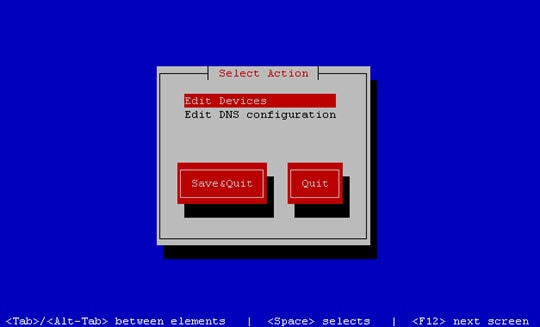
4.![]() In the Select Action screen, select Edit Devices and press Enter (Figure 1).
In the Select Action screen, select Edit Devices and press Enter (Figure 1).
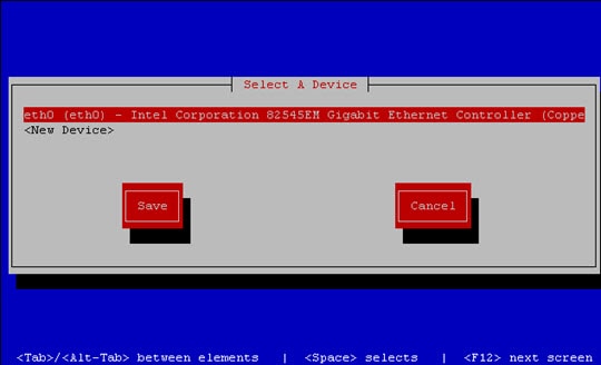
5.![]() In the Select a Device screen, select eth0 and press Enter (Figure 2).
In the Select a Device screen, select eth0 and press Enter (Figure 2).
Figure 2 Select a Device Screen
The Ethernet Configuration screen is displayed (Figure 3).
6.![]() In the Ethernet Configuration screen, do the following:
In the Ethernet Configuration screen, do the following:
Note: The Linux screen is mislabeled “Devernet Configuration.”
Figure 3 Devernet Configuration Screen
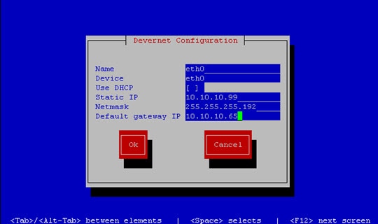
a.![]() Press the Tab key until the cursor is positioned on the Static IP address line.
Press the Tab key until the cursor is positioned on the Static IP address line.
b.![]() Press the backspace key to go to the beginning of the line and type in the IPv4 address of the Cisco Vision Dynamic Signage Director server.
Press the backspace key to go to the beginning of the line and type in the IPv4 address of the Cisco Vision Dynamic Signage Director server.
Note: If installing on a Platform 3 server, this should be a different IP address than what you configured for the CIMC interface.
c.![]() Press the tab key to go to the Netmask line. Type the network mask for the IPv4 address.
Press the tab key to go to the Netmask line. Type the network mask for the IPv4 address.
d.![]() (Optional) In the Default gateway IP line, type the address of the default gateway of your network.
(Optional) In the Default gateway IP line, type the address of the default gateway of your network.
7.![]() When configuration of all options is complete, press the Tab key until the Ok button is selected and press Enter.
When configuration of all options is complete, press the Tab key until the Ok button is selected and press Enter.
You return to the Select a Device screen.
8.![]() Press the Tab key until the Save button is highlighted and press Enter.
Press the Tab key until the Save button is highlighted and press Enter.
You return to the Select Action screen.
9.![]() Press the down arrow key to select the Edit DNS configuration option and press Enter.
Press the down arrow key to select the Edit DNS configuration option and press Enter.
The DNS configuration screen is displayed.
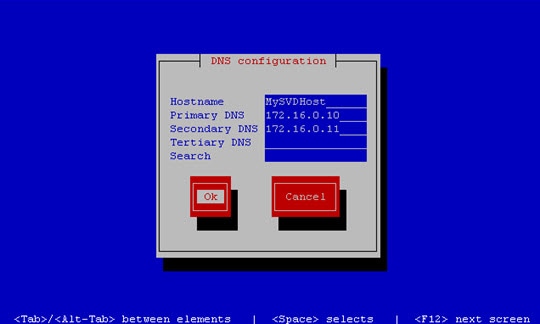
10.![]() In the DNS configuration screen ( Figure 4), select and configure the Hostname and one or more DNS Server IP addresses.
In the DNS configuration screen ( Figure 4), select and configure the Hostname and one or more DNS Server IP addresses.
Note![]() Do not use hostnames that contain periods “.” within the name.
Do not use hostnames that contain periods “.” within the name.
Figure 4 DNS Configuration Screen
11.![]() Press the Tab key until the Ok button is selected and press Enter.
Press the Tab key until the Ok button is selected and press Enter.
You return to the Select Action screen.
12.![]() In the Select Action screen, press the Tab key until the Save&Quit button is selected and press Enter.
In the Select Action screen, press the Tab key until the Save&Quit button is selected and press Enter.
Editing the Hosts File
Note: If for some reason you were unable to complete the Linux network configuration as part of the full ISO installation, then complete this task.
Before you begin, be sure that you know how to use the vi editor. For more information, see Cisco Vision Dynamic Signage Director Server Text Utility Interface.
To edit the hosts file, complete the following steps:
1.![]() From the TUI Network Settings menu, select the Edit hosts file option.
From the TUI Network Settings menu, select the Edit hosts file option.
2.![]() At the confirmation prompt, press any key to open the /etc/hosts file for editing.
At the confirmation prompt, press any key to open the /etc/hosts file for editing.
3.![]() Change the line with IP address “10.10.10.10” to a comment (insert a # character at the beginning of the line) as shown in the following example:
Change the line with IP address “10.10.10.10” to a comment (insert a # character at the beginning of the line) as shown in the following example:
4.![]() Change the line for the IPv6 localhost entry “::1” to a comment as shown in the following example:
Change the line for the IPv6 localhost entry “::1” to a comment as shown in the following example:
5.![]() Add a line for the server IP address and hostname as shown in the following example, where x.x.x.x is the IPv4 address of the Cisco Vision Dynamic Signage Director server, and hostname is the name to identify the server:
Add a line for the server IP address and hostname as shown in the following example, where x.x.x.x is the IPv4 address of the Cisco Vision Dynamic Signage Director server, and hostname is the name to identify the server:
Note: Do not use hostnames that contain periods “.” within the name.
6.![]() Press Esc to enter vi command mode.
Press Esc to enter vi command mode.
7.![]() Save the changes to the file by typing the following command:
Save the changes to the file by typing the following command:
Restarting the Network Service on the Server
Note: If for some reason you were unable to complete the Linux network configuration as part of the full ISO installation, then complete this task.
After you complete the network configuration on the Cisco Vision Dynamic Signage Director server, restart the network service to apply the network configuration.
1.![]() Log into the TUI as installer on the server using a directly-connected console or SSH client.
Log into the TUI as installer on the server using a directly-connected console or SSH client.
The TUI Main Menu is displayed.
2.![]() From the Main Menu, go to Services Control > Networking > Restart networking.
From the Main Menu, go to Services Control > Networking > Restart networking.
The network interface eth0 is restarted.
3.![]() Confirm that the command completed successfully.
Confirm that the command completed successfully.
Generating the SSL Certificate
Note: If for some reason you were unable to complete the Linux network configuration as part of the full ISO installation, then complete this task.
To generate the SSL certificate, complete the following steps:
1.![]() From the Main Menu, go to System Settings > Network Settings.
From the Main Menu, go to System Settings > Network Settings.
2.![]() Select the Generate certificate file option.
Select the Generate certificate file option.
3.![]() When the confirmation warning prompt appears, type Y to continue and generate a new SSL certificate.
When the confirmation warning prompt appears, type Y to continue and generate a new SSL certificate.
Configuring NTP on Cisco Vision Dynamic Signage Director Servers and DMPs
Network Time Protocol (NTP) service is required in Cisco Vision Dynamic Signage Director on the following devices:
■![]() Cisco Vision Dynamic Signage Director servers
Cisco Vision Dynamic Signage Director servers
■![]() Cisco Vision Dynamic Signage Director Remote servers
Cisco Vision Dynamic Signage Director Remote servers
■![]() SV-4K and DMP-2K Precision Time Protocol (PTP) master device
SV-4K and DMP-2K Precision Time Protocol (PTP) master device
NTP provides reliable clocking for your Cisco Vision network. NTP helps ensure synchronicity between redundant servers and the Cisco Vision Dynamic Signage Director remote servers, and optimizes playlist synchronization on the Cisco DMP 4310Gs.
Note: For optimized synchronization on the SV-4K and DMP-2K media players, PTP is used. Only the PTP masters derive a clock using NTP.
You should verify the NTP configuration for your Cisco Vision Dynamic Signage Director servers, since the default NTP source is a Red Hat Linux public pool and might not be the NTP server source that you want to use for your venue.
Configuration of the DMP NTP source is done within the Cisco Vision Dynamic Signage Director Management Dashboard. As a best practice, the Cisco Vision Dynamic Signage Director server is already set as the NTP host by default for all media players. This does not need to be changed unless the venue requires a different NTP source.
Caution: The Cisco Vision Dynamic Signage Director server is itself enabled as an NTP host to provide timing to the media players only. You also can use the Cisco Vision Dynamic Signage Director server as the NTP host for your remote servers. Do not use Cisco Vision Dynamic Signage Director as an NTP host for other devices in your network.
This section includes the following tasks:
■![]() Prerequisites for Configuring NTP on Cisco Vision Dynamic Signage Director Servers and DMPs (required)
Prerequisites for Configuring NTP on Cisco Vision Dynamic Signage Director Servers and DMPs (required)
■![]() Configuring the System Date and Time Using NTP on Cisco Vision Dynamic Signage Director Servers (required)
Configuring the System Date and Time Using NTP on Cisco Vision Dynamic Signage Director Servers (required)
■![]() Configuring NTP on the Cisco DMP 4310G (required)
Configuring NTP on the Cisco DMP 4310G (required)
■![]() Configuring NTP and PTP on the SV-4K and DMP-2K Media Players (required)
Configuring NTP and PTP on the SV-4K and DMP-2K Media Players (required)
Prerequisites for Configuring NTP on Cisco Vision Dynamic Signage Director Servers and DMPs
Caution: If you are running Cisco Vision Dynamic Signage Director on a virtual server, then you should reference a reliable NTP server running on a bare metal server, rather than relying on a clock from a VM environment that can drift and is not accurate.
Before configuring NTP on Cisco Vision Dynamic Signage Director servers and DMPs, be sure that the following requirements are met:
■![]() You understand how to use vi editor commands.
You understand how to use vi editor commands.
■![]() You understand the NTP host requirements for your Cisco Vision Dynamic Signage Director servers:
You understand the NTP host requirements for your Cisco Vision Dynamic Signage Director servers:
–![]() If you do not want to use the default public pool of NTP servers for the Cisco Vision Dynamic Signage Director servers, you have the IP address or DNS name of the NTP host for your network.
If you do not want to use the default public pool of NTP servers for the Cisco Vision Dynamic Signage Director servers, you have the IP address or DNS name of the NTP host for your network.
–![]() If you plan to use a public pool of NTP servers, be sure that the servers are reachable from the Cisco Vision Dynamic Signage Director network. By default, the ntp.conf file on Cisco Vision Dynamic Signage Director servers has configured the following Red Hat Linux public pool of servers:
If you plan to use a public pool of NTP servers, be sure that the servers are reachable from the Cisco Vision Dynamic Signage Director network. By default, the ntp.conf file on Cisco Vision Dynamic Signage Director servers has configured the following Red Hat Linux public pool of servers:
server 0.rhel.pool.ntp.org
server 1.rhel.pool.ntp.org
server 2.rhel.pool.ntp.org
Tip: For more information about using NTP pool servers see the Network Time Protocol website.
■![]() If you plan to change the default best practice of using the Cisco Vision Dynamic Signage Director server as the NTP source for DMPs, be sure that the following requirements are met:
If you plan to change the default best practice of using the Cisco Vision Dynamic Signage Director server as the NTP source for DMPs, be sure that the following requirements are met:
–![]() You have configured the NTP host for the Cisco Vision Dynamic Signage Director server first.
You have configured the NTP host for the Cisco Vision Dynamic Signage Director server first.
–![]() You have upgraded the DMP firmware.
You have upgraded the DMP firmware.
For more information about how to upgrade the DMP firmware, see the Cisco Vision Software Installation and Upgrade Guide: Dynamic Signage Director for your release.
–![]() For optimal synchronization, use the same NTP server that is configured for the Cisco Vision Dynamic Signage Director server. However, it is not required.
For optimal synchronization, use the same NTP server that is configured for the Cisco Vision Dynamic Signage Director server. However, it is not required.
–![]() The DMP must not reference an NTP server pool. If the Cisco Vision Dynamic Signage Director server references an NTP server pool (the default), then select a specific server from that same pool as the NTP server for the DMPs.
The DMP must not reference an NTP server pool. If the Cisco Vision Dynamic Signage Director server references an NTP server pool (the default), then select a specific server from that same pool as the NTP server for the DMPs.
–![]() Only IPv4 is supported for the NTP server address on the DMPs.
Only IPv4 is supported for the NTP server address on the DMPs.
–![]() The NTP server for the DMPs must not be a load-balanced server.
The NTP server for the DMPs must not be a load-balanced server.
■![]() The Cisco Vision Dynamic Signage Director network is configured to allow bidirectional transmission of UDP messages on port 123 for NTP messages.
The Cisco Vision Dynamic Signage Director network is configured to allow bidirectional transmission of UDP messages on port 123 for NTP messages.
UDP port 123 is used for communication between the Cisco Vision Dynamic Signage Director servers and NTP hosts, and the DMPs and NTP host (by default, this is the Cisco Vision Dynamic Signage Director server).
For a complete port reference for Cisco Vision Dynamic Signage Director servers, see the “Port Reference” module of the Cisco Vision Software Installation and Upgrade Guide: Dynamic Signage Director for your release.
Configuring the System Date and Time Using NTP on Cisco Vision Dynamic Signage Director Servers
When you install or upgrade the Cisco Vision Dynamic Signage Director or Cisco Vision Dynamic Signage Director Remote servers, you need to configure the system date and time in the TUI. You also need to configure the time zone.
Note: Although you can manually configure the system date and time on your servers when necessary, this should be avoided for your production network.
■![]() Setting Up the NTP Source on Cisco Vision Dynamic Signage Director Servers (required)
Setting Up the NTP Source on Cisco Vision Dynamic Signage Director Servers (required)
■![]() Configuring the Time Zone (required)
Configuring the Time Zone (required)
■![]() Restarting the Cisco Vision Dynamic Signage Director Software (required)
Restarting the Cisco Vision Dynamic Signage Director Software (required)
■![]() Configuring the Date and Time Manually (if necessary)
Configuring the Date and Time Manually (if necessary)
Setting Up the NTP Source on Cisco Vision Dynamic Signage Director Servers
Note: Complete this task only if you do not want to use the default public pool of servers.
Standard NTP server configuration uses the word “server” followed by the Domain Name System (DNS) name or IP address of an NTP server. By default, the ntp.conf file on Cisco Vision Dynamic Signage Director servers has configured the following Red Hat Linux public pool of servers:
For these servers to be used as a reference clock, they must be reachable from the Cisco Vision Dynamic Signage Director network.
If you want to use your own server, be sure to add it and comment out these default pool servers in the ntp.conf file. Otherwise, you do not need to do any further editing of the ntp.conf file in this task.
To set up the NTP host on Cisco Vision Dynamic Signage Director servers, complete the following steps:
1.![]() From the TUI Main Menu, go to System Settings > Date and Time Settings > Setup NTP Source.
From the TUI Main Menu, go to System Settings > Date and Time Settings > Setup NTP Source.
A confirmation screen to Configure NTP and edit the ntp.conf file is displayed.
2.![]() To open the ntp.conf file for edit, press any key.
To open the ntp.conf file for edit, press any key.
The ntp.conf file opens in the vi editor and the cursor is positioned at the end of the last configured NTP server line. If this is not the case, navigate to the server configuration section.
3.![]() To enter INSERT line editing mode, type i.
To enter INSERT line editing mode, type i.
The vi editor changes to INSERT mode.
4.![]() If you have a server that you want to use as the reference clock source at your site, do the following:
If you have a server that you want to use as the reference clock source at your site, do the following:
–![]() Add a line and type “ server ip-address” or “ server dns-name,” where ip-address or dns-name is replaced by the IP address or name of the NTP server that you want to configure.
Add a line and type “ server ip-address” or “ server dns-name,” where ip-address or dns-name is replaced by the IP address or name of the NTP server that you want to configure.
–![]() Go to the lines where the pool servers are configured and add a “#” sign in front to comment them out of the configuration as shown below:
Go to the lines where the pool servers are configured and add a “#” sign in front to comment them out of the configuration as shown below:
5.![]() To exit INSERT mode and return to vi command mode, press Esc.
To exit INSERT mode and return to vi command mode, press Esc.
6.![]() To save your changes, type :wq.
To save your changes, type :wq.
The configuration is saved and the ntpd service is restarted. Verify that you see the “OK” confirmation that the ntpd has started.
7.![]() To return to the Date and Time Settings menu, press any key.
To return to the Date and Time Settings menu, press any key.
Configuring the Time Zone
Configuring the time zone is required for both the Cisco Vision Dynamic Signage Director and Cisco Vision Dynamic Signage Director Remote servers.
Note: Although there is an option to set the time zone in the Venues interface of the Control Panel on the Cisco Vision Dynamic Signage Director server, this option is informational only and is also used for proof-of-play reporting. The actual time zone for the venue is configured from the TUI on the remote server.
This section includes the following tasks:
■![]() Finding the Time Zone Code for System Configuration (optional)
Finding the Time Zone Code for System Configuration (optional)
■![]() Configuring the System Time Zone (required)
Configuring the System Time Zone (required)
Finding the Time Zone Code for System Configuration
Use this task if you need to find out the time zone code to configure the server’s time zone information.
Note: This task provides information only and does not actually configure the time zone.
To find the time zone code for system configuration, complete the following steps:
a.![]() From the Date and Time Settings menu, do the following:
From the Date and Time Settings menu, do the following:
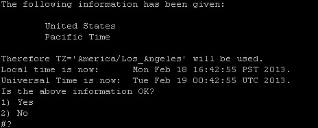
c.![]() Type the number that corresponds to the applicable continent or ocean for the location of the remote server.
Type the number that corresponds to the applicable continent or ocean for the location of the remote server.
d.![]() Type the number that corresponds to the country.
Type the number that corresponds to the country.
e.![]() Type the number for the time zone (as applicable).
Type the number for the time zone (as applicable).
f.![]() When the confirmation of the time zone information that you configured is displayed, type 1 ( for Yes) to accept your settings, or 2 (for No) to cancel (Figure 5).
When the confirmation of the time zone information that you configured is displayed, type 1 ( for Yes) to accept your settings, or 2 (for No) to cancel (Figure 5).
Figure 5 Time Zone Confirmation Prompt
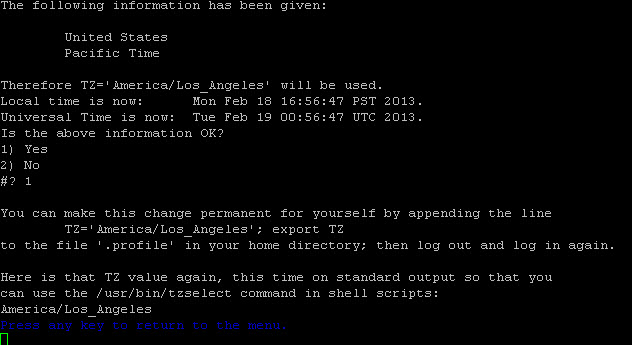
g.![]() After confirming Yes at the prompt, note the time zone string that is provided.
After confirming Yes at the prompt, note the time zone string that is provided.
Figure 6 shows a sample time zone code for America/Los_Angeles.
Figure 6 Sample Time Zone Code
8.![]() Press any key to return to the Date and Time Settings menu.
Press any key to return to the Date and Time Settings menu.
9.![]() Configure the system time zone using the appropriate code for the server location. See Configuring the System Time Zone.
Configure the system time zone using the appropriate code for the server location. See Configuring the System Time Zone.
Configuring the System Time Zone
Before you configure the system time zone, you should know the following information:
■![]() How to use vi editor commands.
How to use vi editor commands.
■![]() The time zone code for the server location. If you need to look up the time zone code, see Finding the Time Zone Code for System Configuration.
The time zone code for the server location. If you need to look up the time zone code, see Finding the Time Zone Code for System Configuration.
To configure the system time zone so that it persists after restart of the server, complete the following steps:
1.![]() From the TUI Main Menu on the server, go to System Settings > Date and Time Settings > Change System Timezone.
From the TUI Main Menu on the server, go to System Settings > Date and Time Settings > Change System Timezone.
2.![]() At the prompt to edit the system clock file, press any key to continue.
At the prompt to edit the system clock file, press any key to continue.
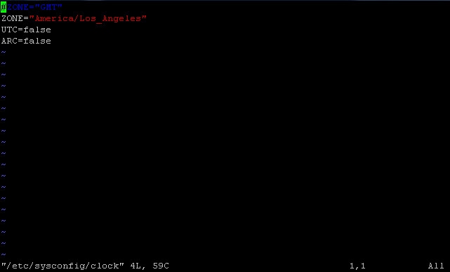
The /etc/sysconfig/clock file is opened for editing.
3.![]() Use the vi editor to specify your time zone. Figure 7 shows an entry for the “America/Los_Angeles” time zone code.
Use the vi editor to specify your time zone. Figure 7 shows an entry for the “America/Los_Angeles” time zone code.
Tip: The quotation marks and underscore symbols are required.
Figure 7 Editing the Clock File
4.![]() To exit INSERT mode and return to vi command mode, press Esc.
To exit INSERT mode and return to vi command mode, press Esc.
5.![]() To save your changes, type :wq!.
To save your changes, type :wq!.
6.![]() At the prompt, press any key to return to the Date and Time Settings menu.
At the prompt, press any key to return to the Date and Time Settings menu.
7.![]() Restart the server to put the time zone changes into effect.
Restart the server to put the time zone changes into effect.
Restarting the Cisco Vision Dynamic Signage Director Software
After you configure an NTP server and time zone in the TUI on the server, you must restart the software on the Cisco Vision Dynamic Signage Director or Cisco Vision Dynamic Signage Director Remote server.
To restart the Cisco Vision Dynamic Signage Director software, complete the following steps:
1.![]() From the TUI Main Menu on the server, do one of the following according to the server that you need to restart:
From the TUI Main Menu on the server, do one of the following according to the server that you need to restart:
–![]() Go to Cisco Vision Server Administration > Restart Cisco Vision Dynamic Signage Director software.
Go to Cisco Vision Server Administration > Restart Cisco Vision Dynamic Signage Director software.
–![]() Go to StadiumVision Remote Server Administration > Restart StadiumVision Remote software.
Go to StadiumVision Remote Server Administration > Restart StadiumVision Remote software.
Cisco Vision Dynamic Signage Director Remote distribution is stopped and restarted.
2.![]() When the prompt appears, press any key to return to the Server Administration menu.
When the prompt appears, press any key to return to the Server Administration menu.
Configuring the Date and Time Manually
Note: This task is provided as a precaution if you should find it necessary to manually set the system date and time. Manual date and time configuration should be avoided on a production system and NTP service used instead.
To configure the date and time manually, complete the following steps:
1.![]() From the TUI Main Menu on the server, go to System Settings > Date and Time Settings > Change Date and Time.
From the TUI Main Menu on the server, go to System Settings > Date and Time Settings > Change Date and Time.
2.![]() At the confirmation prompt, type Y to continue.
At the confirmation prompt, type Y to continue.
3.![]() Type the new date and time in the format: MMDDhhmm[[CC] YY] [.ss], where:
Type the new date and time in the format: MMDDhhmm[[CC] YY] [.ss], where:
–![]() MMDDhhmm is required (MM is month, DD is day, hh is hour, and mm is minutes).
MMDDhhmm is required (MM is month, DD is day, hh is hour, and mm is minutes).
–![]() CC is the century (first 2 digits of the year) and is optional for use with YY. For example “20” in the year 2013.
CC is the century (first 2 digits of the year) and is optional for use with YY. For example “20” in the year 2013.
–![]() YY is the last 2 digits of the year and is optional. For example “13” in the year 2013.
YY is the last 2 digits of the year and is optional. For example “13” in the year 2013.
–![]() .ss is seconds and is optional.
.ss is seconds and is optional.
4.![]() Press any key to return to the Date and Time Settings menu.
Press any key to return to the Date and Time Settings menu.
Configuring NTP on the Cisco DMP 4310G
In Release 3.2 and later releases, you must configure NTP on the Cisco Vision Dynamic Signage Director server and the Cisco DMP 4310Gs. Granules are no longer used in Cisco Vision Dynamic Signage Director for timing with the DMPs.
Through default MIB settings on the DMPs, the following values are preset and should not be modified:
■![]() Time zone—Etc/UTC Coordinated Universal Time.
Time zone—Etc/UTC Coordinated Universal Time.
Generally, the only values that you might consider changing are the NTP host and the sync interval. These values can be configured both globally and for selected DMPs.
This section includes the following tasks:
■![]() Applying the Standard NTP Configuration on All Cisco DMP 4310Gs in the System (recommended)
Applying the Standard NTP Configuration on All Cisco DMP 4310Gs in the System (recommended)
■![]() Modifying the Standard NTP Configuration Globally on all Cisco DMP 4310Gs (optional)
Modifying the Standard NTP Configuration Globally on all Cisco DMP 4310Gs (optional)
■![]() Modifying the Standard NTP Configuration on Selected Cisco DMP 4310Gs in the System (optional)
Modifying the Standard NTP Configuration on Selected Cisco DMP 4310Gs in the System (optional)
■![]() Verifying Time Synchronization on the Cisco DMP 4310G (recommended)
Verifying Time Synchronization on the Cisco DMP 4310G (recommended)
Applying the Standard NTP Configuration on All Cisco DMP 4310Gs in the System
The NTP service is automatically enabled for Cisco DMP 4310Gs, and uses the Cisco Vision Dynamic Signage Director server as the host. If you do not plan to change the NTP host, then you can simply run the Global DMP Settings command to apply the standard configuration on all DMPs in the system.
To apply the standard NTP configuration on all Cisco DMP 4310Gs, complete the following steps:
1.![]() Log into the Cisco Vision Dynamic Signage Director server as an administrator.
Log into the Cisco Vision Dynamic Signage Director server as an administrator.
2.![]() Go to the Management Dashboard.
Go to the Management Dashboard.
3.![]() Go to DMP and TV Controls > Global Settings > Global DMP Settings.
Go to DMP and TV Controls > Global Settings > Global DMP Settings.
4.![]() Select All Devices and click the Play ( >) icon to run the command.
Select All Devices and click the Play ( >) icon to run the command.
All global MIB settings, including the new NTP settings, are sent to all DMPs.
Modifying the Standard NTP Configuration Globally on all Cisco DMP 4310Gs
Table 1 provides information about all of the global DMP NTP properties that can be specified in the Management Dashboard to control NTP service on all Cisco DMP 4310Gs.
To modify the standard NTP configuration globally on all Cisco DMP 4310Gs, complete the following steps:
1.![]() Log into the Cisco Vision Dynamic Signage Director server as an administrator.
Log into the Cisco Vision Dynamic Signage Director server as an administrator.
2.![]() Go to the Management Dashboard.
Go to the Management Dashboard.
3.![]() Click Dynamic Signage Director Configuration > System Configuration > Global DMP Settings > 4310 v5.x.x (Figure 8).
Click Dynamic Signage Director Configuration > System Configuration > Global DMP Settings > 4310 v5.x.x (Figure 8).
Figure 8 Global DMP Settings for NTP for the Cisco DMP 4310G
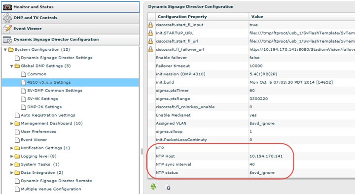
1.![]() To change the NTP Host, type the IPv4 address of the NTP server that you want the DMPs to reference.
To change the NTP Host, type the IPv4 address of the NTP server that you want the DMPs to reference.
2.![]() (Optional) In the NTP status property, change the IP address and stratum number according to the new NTP host.
(Optional) In the NTP status property, change the IP address and stratum number according to the new NTP host.
Note: To skip this field when performing DMP compliance checking, use the $svd_ignore value.
3.![]() (Optional) Change other global NTP properties as required for your environment. Refer to Table 1.
(Optional) Change other global NTP properties as required for your environment. Refer to Table 1.
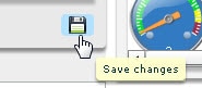
4.![]() Click the disk icon to Save changes (Figure 9).
Click the disk icon to Save changes (Figure 9).
5.![]() Go to DMP and TV Controls > Global Settings > Global DMP Settings.
Go to DMP and TV Controls > Global Settings > Global DMP Settings.
6.![]() Select All Devices and click the Play ( >) icon to run the command.
Select All Devices and click the Play ( >) icon to run the command.
All global MIB settings, including the new NTP settings, are sent to all DMPs.
Modifying the Standard NTP Configuration on Selected Cisco DMP 4310Gs in the System
Table 2 describes all of the NTP MIBs and their default values.
Note: Under normal operation, only the ntpc.hostname and ntpc.interval MIBs should be modified
To modify the standard NTP configuration on selected Cisco DMP 4310Gs, complete the following steps:
1.![]() Log into the Cisco Vision Dynamic Signage Director server as an administrator.
Log into the Cisco Vision Dynamic Signage Director server as an administrator.
2.![]() Go to the Management Dashboard.
Go to the Management Dashboard.
3.![]() Click DMP and TV Controls > DMP Install > Setup NTP ( Figure 10).
Click DMP and TV Controls > DMP Install > Setup NTP ( Figure 10).
Figure 10 DMP and TV Controls Setup NTP MIBs
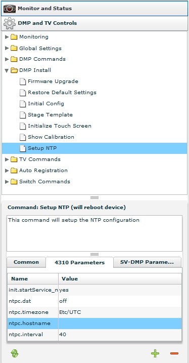
1.![]() From the 4310 Parameters tab in the Command:Setup NTP section, specify the values of the NTP MIB variables according to the recommended and required values in Table 2.
From the 4310 Parameters tab in the Command:Setup NTP section, specify the values of the NTP MIB variables according to the recommended and required values in Table 2.
2.![]() In the Select Devices panel, select the DMPs where you want to setup the NTP service.
In the Select Devices panel, select the DMPs where you want to setup the NTP service.
3.![]() Click the Play button to set the MIB values on the selected devices.
Click the Play button to set the MIB values on the selected devices.
Verifying Time Synchronization on the Cisco DMP 4310G
You can find DMPs that are having problems synchronizing with the NTP server using the DMP compliance check in the Management Dashboard.
Before you can run a valid DMP compliance check for the DMP synchronization status, the “ Synchronized to server svd-ip at stratum n” value of the NTP status global DMP properties must reflect the IP address of your NTP host and its stratum level.
Note: Outside of Cisco Vision Dynamic Signage Director, if you know the DMP IP address, you can find a single DMP’s NTP status using a web browser and going to either of the following URLs:
http:// dmpIpAddress
https:// dmpIpAddress /get_param?p=*
Find “ntpc.status”. A sample line depicting unsuccessful time synchronization is:
To verify time synchronization on the Cisco DMP 4310G, complete the following steps:
1.![]() Do one of the following to find and confirm the stratum level for the NTP host:
Do one of the following to find and confirm the stratum level for the NTP host:
If you are using the Cisco Vision Dynamic Signage Director server as the NTP host:
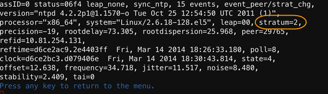
–![]() Log into the TUI and go to Troubleshooting > NTP > Local clock state (Figure 11).
Log into the TUI and go to Troubleshooting > NTP > Local clock state (Figure 11).
Figure 11 Stratum Field in Local Clock State TUI Output
Note: Alternatively, you can run a DMP Get Status command on one of the DMPs from the Management Dashboard and find the value reported in it ntpc.status MIB value.
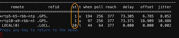
If you are using an NTP host other than the Cisco Vision Dynamic Signage Director server:
–![]() Log into the TUI and go to Troubleshooting > NTP > Show configured peers and clients. Find the configured NTP host in the “refid” field and its corresponding stratum level under the “st” column.
Log into the TUI and go to Troubleshooting > NTP > Show configured peers and clients. Find the configured NTP host in the “refid” field and its corresponding stratum level under the “st” column.
Figure 12 Stratum Field in Show Configured Peers and Clients Output
2.![]() Go to the Management Dashboard and do the following:
Go to the Management Dashboard and do the following:
–![]() In the NTP status property, type the value to “ Synchronized to server svd-ip at stratum n” and be sure that the IP address is set to your NTP host and the stratum level matches the level that you confirmed in Step 1.
In the NTP status property, type the value to “ Synchronized to server svd-ip at stratum n” and be sure that the IP address is set to your NTP host and the stratum level matches the level that you confirmed in Step 1.
–![]() Run the Global DMP settings command to apply the configuration to all DMPs.
Run the Global DMP settings command to apply the configuration to all DMPs.
See Modifying the Standard NTP Configuration Globally on all Cisco DMP 4310Gs for more information.
3.![]() Go to the Management Dashboard.
Go to the Management Dashboard.
4.![]() Click DMP and TV Controls > Monitoring > Get Status.
Click DMP and TV Controls > Monitoring > Get Status.
5.![]() At the bottom of the screen, go to Status > Compliance.
At the bottom of the screen, go to Status > Compliance.
6.![]() Find ntpc.status MIB and look for information about the synchronization status, such as “Not synchronized.”
Find ntpc.status MIB and look for information about the synchronization status, such as “Not synchronized.”
If your DMPs are not synchronized, see What To Do Next.
What To Do Next
If you find that DMPs are not synchronized:
■![]() Confirm that you have met the requirements described in Prerequisites for Configuring NTP on Cisco Vision Dynamic Signage Director Servers and DMPs.
Confirm that you have met the requirements described in Prerequisites for Configuring NTP on Cisco Vision Dynamic Signage Director Servers and DMPs.
■![]() Verify your NTP host configuration to be sure that the proper IP address is configured.
Verify your NTP host configuration to be sure that the proper IP address is configured.
■![]() Verify reachability of the NTP server from the DMPs in your Cisco Vision Dynamic Signage Director network.
Verify reachability of the NTP server from the DMPs in your Cisco Vision Dynamic Signage Director network.
For more information about other NTP troubleshooting on your network, look up NTP debugging techniques provided by the ntp.org project on the world wide web.
Note: After you verify DMP NTP synchronization, be sure to reset the NTP status field back to $svd_ignore because the stratum value can change.
Configuring NTP and PTP on the SV-4K and DMP-2K Media Players
By default, both NTP and PTP services are automatically enabled for SV-4K and DMP-2K media players. The SV-4K and DMP-2K media players use PTP to achieve optimal synchronization. However, an NTP source also must be used to provide initial clocking to the devices that are elected PTP masters in the network.
This section provides information about the default settings and how to modify them. It includes the following tasks:
■![]() Restrictions for NTP and PTP on the SV-4K and DMP-2K Media Players
Restrictions for NTP and PTP on the SV-4K and DMP-2K Media Players
■![]() Guidelines for NTP and PTP on the SV-4K and DMP-2K Media Players
Guidelines for NTP and PTP on the SV-4K and DMP-2K Media Players
■![]() Modifying the Standard NTP and PTP Configuration on All SV-4K and DMP-2Ks in the System (optional)
Modifying the Standard NTP and PTP Configuration on All SV-4K and DMP-2Ks in the System (optional)
■![]() Verifying PTP Operation for the SV-4K and DMP-2K Media Player
Verifying PTP Operation for the SV-4K and DMP-2K Media Player
Restrictions for NTP and PTP on the SV-4K and DMP-2K Media Players
Before you configure PTP on the SV-4K and DMP-2K media players, consider the following restrictions:
■![]() By default, PTP messages will not cross VLANs and PTP master candidates need to be identified for each VLAN and configured in the Management Dashboard.
By default, PTP messages will not cross VLANs and PTP master candidates need to be identified for each VLAN and configured in the Management Dashboard.
However, Release 4.1 and later supports a configurable Precision Time Protocol (PTP) Time To Live (TTL) setting in the Management Dashboard. The PTP TTL specifies the number of VLANs that can be crossed for selection of a PTP master. The default value of 1 (recommended) means that each VLAN will elect its own PTP master.
Note: For ease of configuration for venues with multiple VLANs, the system is configured by default to list all SV-4K and DMP-2K devices as eligible PTP master candidates. However, be aware that although this simplifies configuration, the time that it takes for the SV-4K and DMP-2Ks to arbitrate a master device in each network will vary, and depends on the number of eligible devices in each network.
■![]() Content synchronization for video playback on the SV-4K and DMP-2K media player relies on precise time across DMPs using PTP. The behavior is similar to content synchronization on the Cisco DMP 4310G. If SV-4K and DMP-2K devices are playing video and one of the devices reboots, the rebooting unit will restart video playback from the beginning and will only synchronize with the other players when the next item in the playlist is rendered.
Content synchronization for video playback on the SV-4K and DMP-2K media player relies on precise time across DMPs using PTP. The behavior is similar to content synchronization on the Cisco DMP 4310G. If SV-4K and DMP-2K devices are playing video and one of the devices reboots, the rebooting unit will restart video playback from the beginning and will only synchronize with the other players when the next item in the playlist is rendered.
If SV-4K and DMP-2Ks are participating in zone-based content synchronization for video walls, with some enhanced synchronization capability, the rebooting unit will synchronize with the current item being played by the device leader in the video wall. For more information, see the “Working with Video Walls” section of the Cisco Vision Operations Guide: Dynamic Signage Director Release 5.0.
Guidelines for NTP and PTP on the SV-4K and DMP-2K Media Players
Before you configure NTP and PTP on the SV-4K and DMP-2K media players, consider the following guidelines:
■![]() For new installations of Cisco Vision Dynamic Signage Director, PTP is the default time source for the SV-4K and DMP-2K media players, with NTP as the default time source for the elected PTP master.
For new installations of Cisco Vision Dynamic Signage Director, PTP is the default time source for the SV-4K and DMP-2K media players, with NTP as the default time source for the elected PTP master.
■![]() Each SV-4K and DMP-2K media player designated as PTP master (per VLAN) will use NTP as its time source. The other devices in the network operate using a PTP reference clock from the elected PTP master.
Each SV-4K and DMP-2K media player designated as PTP master (per VLAN) will use NTP as its time source. The other devices in the network operate using a PTP reference clock from the elected PTP master.
■![]() When PTP is disabled (not recommended), all SV-4K and DMP-2K devices use NTP to set their local clock.
When PTP is disabled (not recommended), all SV-4K and DMP-2K devices use NTP to set their local clock.
Note: For synchronized video playback, NTP alone cannot be relied upon for SV-4K and DMP-2K devices and PTP must be used.
■![]() The default NTP synchronization interval with the host time server is one hour and is configurable.
The default NTP synchronization interval with the host time server is one hour and is configurable.
■![]() An NTP source must be configured in Cisco Vision Dynamic Signage Director. By default, the Cisco Vision Dynamic Signage Director server is configured as the SV-4K and DMP-2K NTP host (just as with the Cisco DMP 4310G).
An NTP source must be configured in Cisco Vision Dynamic Signage Director. By default, the Cisco Vision Dynamic Signage Director server is configured as the SV-4K and DMP-2K NTP host (just as with the Cisco DMP 4310G).
■![]() PTP version 2 is supported only for the SV-4K and DMP-2K media players and applies globally to all devices in the Cisco Vision Dynamic Signage Director network when configured.
PTP version 2 is supported only for the SV-4K and DMP-2K media players and applies globally to all devices in the Cisco Vision Dynamic Signage Director network when configured.
■![]() PTP configuration includes a PTP domain and a set of master candidates:
PTP configuration includes a PTP domain and a set of master candidates:
Be sure that this domain does not conflict with any other PTP domain (and multicast addressing) in use in your network, and revise as needed. See Table 3 for more information.
–![]() PTP master candidates—Default is *.
PTP master candidates—Default is *.
This specifies that all SV-4K and DMP-2K devices in the network are eligible as master candidates and will go through arbitration to designate a master for their respective subnets.
■![]() If you revise the default PTP master candidates configuration, you must configure one or more SV-4K and DMP-2K devices as master candidates in a semicolon-separated list of IP addresses for each VLAN.
If you revise the default PTP master candidates configuration, you must configure one or more SV-4K and DMP-2K devices as master candidates in a semicolon-separated list of IP addresses for each VLAN.
A minimum of two master candidates per network is recommended.
■![]() If there is an in-house PTP master for your network, leave the “PTP master candidates” property value blank. However, this configuration is only supported for venues without multiple subnets.
If there is an in-house PTP master for your network, leave the “PTP master candidates” property value blank. However, this configuration is only supported for venues without multiple subnets.
Modifying the Standard NTP and PTP Configuration on All SV-4K and DMP-2Ks in the System
By default the NTP and PTP services are automatically enabled and configured for SV-4K and DMP-2K media players. Use this task if you need to modify the default settings described in Table 3 and Table 4.
To modify the standard NTP and PTP configuration on all SV-4K and DMP-2Ks, complete the following steps:
1.![]() Log into the Cisco Vision Dynamic Signage Director server as an administrator.
Log into the Cisco Vision Dynamic Signage Director server as an administrator.
2.![]() Go to the Management Dashboard.
Go to the Management Dashboard.
3.![]() Go to Dynamic Signage Director Configuration > System Configuration > Global DMP Settings > SV-DMP Common Settings (Figure 13).
Go to Dynamic Signage Director Configuration > System Configuration > Global DMP Settings > SV-DMP Common Settings (Figure 13).
Figure 13 Global DMP Settings for NTP and PTP on the SV-4K and DMP-2K
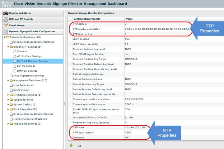
4.![]() (Optional) Change the global PTP properties as required for your network. Refer to Table 3.
(Optional) Change the global PTP properties as required for your network. Refer to Table 3.
5.![]() (Optional) Change the global NTP properties as required for your environment. Refer to Table 4.
(Optional) Change the global NTP properties as required for your environment. Refer to Table 4.
Verifying PTP Operation for the SV-4K and DMP-2K Media Player
This section describes how to verify the PTP configuration and also the operation of PTP for your SV-4K and DMP-2K devices.
To verify the PTP operation for the SV-4K and DMP-2K media player, complete the following steps:
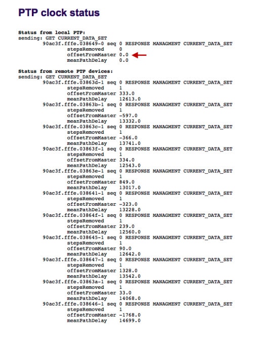
1.![]() Open your browser and navigate to one of the DMPs:
Open your browser and navigate to one of the DMPs:
http:// sv4k-ip-address /ptp.html
2.![]() Identify the PTP master by finding the unit that has an "offsetFromMaster" value of 0.0.
Identify the PTP master by finding the unit that has an "offsetFromMaster" value of 0.0.
Figure 14 highlights the PTP master and shows a network where PTP is operating successfully with 12 members.
Figure 14 Successful PTP Clock Operation
Configuring Multicast Ports for Cisco Vision Dynamic Signage Director
This section includes the following topics:
■![]() Information about Multicast Support in Cisco Vision Dynamic Signage Director
Information about Multicast Support in Cisco Vision Dynamic Signage Director
■![]() Prerequisites for Configuring Multicast Ports in Cisco Vision Dynamic Signage Director
Prerequisites for Configuring Multicast Ports in Cisco Vision Dynamic Signage Director
■![]() How to Configure Multicast Ports in Cisco Vision Dynamic Signage Director
How to Configure Multicast Ports in Cisco Vision Dynamic Signage Director
Information about Multicast Support in Cisco Vision Dynamic Signage Director
This section includes the following topics:
■![]() HDMI-In Encoding on the SV-4K Media Player to Stream Video as a Channel
HDMI-In Encoding on the SV-4K Media Player to Stream Video as a Channel
■![]() Per-Script Multicast Optimization
Per-Script Multicast Optimization
■![]() Multicast Registry Keys in Cisco Vision Dynamic Signage Director
Multicast Registry Keys in Cisco Vision Dynamic Signage Director
HDMI-In Encoding on the SV-4K Media Player to Stream Video as a Channel
In Release 4.1 and later releases, Cisco Vision Dynamic Signage Director supports streaming video from a laptop or other supported device connected to the HDMI-In port on an SV-4K media player to be played as a multicast-based channel in Cisco Vision Dynamic Signage Director.
The allowable multicast range to use for this feature in the Connected Venue (Connected Stadium) network is 239.193.20.0/24.
Note: If you want to maintain privacy of channels, create a DMP-encoded channel per suite with a unique multicast address (from 239.193.20.0/24 range), and create a separate channel guide per suite. For example, if you have 10 suites—create 10 separate DMP-encoded channels with unique multicast addresses, create 10 different channel guides for each DMP-encoded channel, and assign each suite to a different channel guide.
For more information about configuring this feature, see the Cisco StadiumVision Director Operations Guide.
Per-Script Multicast Optimization
In Cisco StadiumVision Director Release 3.2 and later releases, the original Multicast Optimization introduced in Release 3.1 is replaced by Per-Script Multicast Optimization (for up to 20 different scripts) to reduce the number of multicast messages that each DMP must process.
Per-Script Multicast Optimization is designed to reduce the load on DMPs when the following conditions are present in Cisco StadiumVision Director:
■![]() More than one event script is run simultaneously in a venue.
More than one event script is run simultaneously in a venue.
The scripts can be running across multiple venues, scripts running in a single venue, or running in systems without Cisco Vision Dynamic Signage Director Remote servers.
■![]() The External Content Integration feature is used, which sends multiple messages to the DMPs in a script.
The External Content Integration feature is used, which sends multiple messages to the DMPs in a script.
Table 5 provides a summary of the two different multicast optimization features supported in Cisco Vision Dynamic Signage Director.
Multicast Optimization1 |
||||
Per Script |
|
1.For information about per-site multicast optimization in Cisco StadiumVision Director Release 3.1, see the “Multicast Optimization for Remote Venues” topic in the “Configuring Cisco StadiumVision Director for Multiple Venue Support” module of the Cisco StadiumVision Director Server Administration Guide, Release 3.1. 2.If you are running more than 20 scripts, then the first 20 scripts operate using per-script multicast channels, and the additional scripts are run over the global multicast host port. |
Benefits of Per-Script Multicast
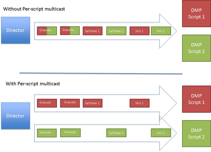
In releases of Cisco StadiumVision Director 3.1 and earlier, the server uses a single multicast channel for all DMPs. In Release 3.2 and later, you can configure multiple multicast channels, over which the server sends only the multicast messages needed for a particular event script for up to 20 scripts.
If you are running more than 20 scripts, then the first 20 scripts operate using per-script multicast channels, and the additional scripts are run over the global multicast host port.
Figure 15 shows this message separation. Each DMP goes from seeing four packets to seeing two. More importantly, each DMP now only has to process one XML payload, which is important when the XML payloads are sizeable.
Figure 15 Multicast Messaging With and Without Per-Script Multicast Optimization
All DMPs, including those associated with a Cisco Vision Dynamic Signage Director Remote server, listen on these per-script multicast channels.
For messages that apply to multiple event scripts, the message is duplicated and sent to each multicast channel. Therefore, this feature can increase the load on Cisco Vision Dynamic Signage Director and Cisco Vision Dynamic Signage Director Remote servers (increasing the number of messages sent and copying of messages) as a tradeoff for reducing the number of messages seen and processed by DMPs. However, this load is expected to be negligible.
Multicast Registry Keys in Cisco Vision Dynamic Signage Director
Cisco Vision Dynamic Signage Director uses multicast messages for DMP control-plane operation. Cisco Connected Venue (Connected Stadium) network design assigns the following multicast group addresses for use by Cisco Vision Dynamic Signage Director:
■![]() 239.193.0.0/24—For control communication
239.193.0.0/24—For control communication
■![]() 239.192.0.0/24—For video communication (This network should be avoided for the multicast configuration described in this module.)
239.192.0.0/24—For video communication (This network should be avoided for the multicast configuration described in this module.)
Multicast addressing is configured using registry keys from the Cisco Vision Dynamic Signage Director Management Dashboard.
Table 6 describes the registry keys in Cisco Vision Dynamic Signage Director that control the multicast configuration.
Note: The default PTP domain 0 uses multicast address 224.0.1.129. For more information, see Table 3.
Prerequisites for Configuring Multicast Ports in Cisco Vision Dynamic Signage Director
Before you configure multicast ports, be sure that the following requirements are met:
■![]() Be sure that you understand the multicast addressing in use for all areas of your Cisco Vision Dynamic Signage Director network, including Cisco Connected Venue and Cisco Vision Mobile networks. Confirm that there are not any multicast address/port overlaps.
Be sure that you understand the multicast addressing in use for all areas of your Cisco Vision Dynamic Signage Director network, including Cisco Connected Venue and Cisco Vision Mobile networks. Confirm that there are not any multicast address/port overlaps.
Caution: Because of the large number of ports that per-script multicast configuration requires, and the possibility for hard-to-diagnose failures if video is routed to a DMP's control channel (which can occur when the port numbers are the same and even if the group/host portion is different), it is critical to verify that the port ranges you plan to use are not used by any other source of multicast in the network.
–![]() For a summary of all of the input and output ports in use by Cisco Vision Dynamic Signage Director and Cisco Vision Dynamic Signage Director Remote, see the “Appendix B: Port Reference” module in the Cisco Vision Software Installation and Upgrade Guide: Dynamic Signage Director Release 5.0.
For a summary of all of the input and output ports in use by Cisco Vision Dynamic Signage Director and Cisco Vision Dynamic Signage Director Remote, see the “Appendix B: Port Reference” module in the Cisco Vision Software Installation and Upgrade Guide: Dynamic Signage Director Release 5.0.
–![]() For more information about the recommended multicast addressing for the Cisco Connected Venue network, see the Cisco Connected Stadium Design Guide available to authorized partners and from your Cisco Systems representative.
For more information about the recommended multicast addressing for the Cisco Connected Venue network, see the Cisco Connected Stadium Design Guide available to authorized partners and from your Cisco Systems representative.
■![]() The network is properly configured to route the global multicast host port to be visible for all DMPs in the Cisco Vision Dynamic Signage Director network, including those at remote venues and associated to venues in a multi-venue environment.
The network is properly configured to route the global multicast host port to be visible for all DMPs in the Cisco Vision Dynamic Signage Director network, including those at remote venues and associated to venues in a multi-venue environment.
How to Configure Multicast Ports in Cisco Vision Dynamic Signage Director
This section includes the following tasks:
■![]() Configuring the Global Multicast Host Port in Cisco Vision Dynamic Signage Director (required)
Configuring the Global Multicast Host Port in Cisco Vision Dynamic Signage Director (required)
■![]() Configuring Per-Script Multicast in Cisco Vision Dynamic Signage Director (recommended)
Configuring Per-Script Multicast in Cisco Vision Dynamic Signage Director (recommended)
■![]() Configuring Multicast Support for Zone-Based Content Synchronization for the SV-4K and DMP-2K (optional)
Configuring Multicast Support for Zone-Based Content Synchronization for the SV-4K and DMP-2K (optional)
Configuring the Global Multicast Host Port in Cisco Vision Dynamic Signage Director
The global multicast host port is used by Cisco Vision Dynamic Signage Director to send messages to DMPs when they are not part of a script, when per-script multicast is disabled, or when the number of scripts running exceeds to configured maximum of per-script multicast ports.
It is configured in the “MulticastHostPort” registry key in the Management Dashboard.
Note: The default value currently uses the address 239.192.0.254:50001 and should be changed to a network address in the range 239.193.0.0/24.
To verify or configure the multicast addressing for Cisco Vision Dynamic Signage Director, complete the following steps:
1.![]() From the Management Dashboard, select Tools > Advanced > Registry.
From the Management Dashboard, select Tools > Advanced > Registry.
2.![]() Scroll to the “MulticastHostPort” registry key in the Parameters list and confirm the entry for the registry.
Scroll to the “MulticastHostPort” registry key in the Parameters list and confirm the entry for the registry.
3.![]() Click on the value field and specify a multicast address in the range 239.193.0.0/24 and port number.
Click on the value field and specify a multicast address in the range 239.193.0.0/24 and port number.
Note: Be sure to use the value that is configured in your Cisco Connected Venue network for Cisco Vision Dynamic Signage Director control messages and include the :port. The recommended default is :50001.
Configuring Per-Script Multicast in Cisco Vision Dynamic Signage Director
By default, Per-Script Multicast Optimization is disabled and the Cisco Vision Dynamic Signage Director server sends all communication over the MulticastHostPort address directly to all DMPs and Cisco Vision Dynamic Signage Director Remote servers, including all remote DMPs.
To configure per-script multicast, complete the following steps:
1.![]() From the Management Dashboard, select Tools > Advanced > Registry.
From the Management Dashboard, select Tools > Advanced > Registry.
2.![]() To enable per-script multicast, change the values of the following registry keys:
To enable per-script multicast, change the values of the following registry keys:
–![]() transport.dynamic.enable —Specify a value of true.
transport.dynamic.enable —Specify a value of true.
–![]() transport.dynamic.send_range —(As Required) Change the range of ports to comply with your network configuration. The default is 50080-50099.
transport.dynamic.send_range —(As Required) Change the range of ports to comply with your network configuration. The default is 50080-50099.
Note: Be sure that these ports do not overlap with other multicast ports in use on your network.
4.![]() Reload the Flash template on all DMPs:
Reload the Flash template on all DMPs:
a.![]() From the DMP and TV Controls dashboard drawer, navigate to and select the following command: DMP and TV Controls > DMP Install > Stage Template.
From the DMP and TV Controls dashboard drawer, navigate to and select the following command: DMP and TV Controls > DMP Install > Stage Template.
b.![]() Select all of the DMP devices where the command should be applied.
Select all of the DMP devices where the command should be applied.
c.![]() Click the Play button to run the command on the selected devices.
Click the Play button to run the command on the selected devices.
5.![]() To verify the configuration:
To verify the configuration:
a.![]() Start and stop event scripts and change states.
Start and stop event scripts and change states.
b.![]() Verify that the multicast port that the DMP is listening on is one of the per-script ports (50080-50099 by default), rather than the global multicast hostport (50001).
Verify that the multicast port that the DMP is listening on is one of the per-script ports (50080-50099 by default), rather than the global multicast hostport (50001).
If the scripts do not start and stop, see Troubleshooting Per-Script Multicast Configuration.
Troubleshooting Per-Script Multicast Configuration
This section includes information about troubleshooting the following behaviors when per-script multicast optimization is enabled:
■![]() Scripts Unable to Start or Stop
Scripts Unable to Start or Stop
Scripts Unable to Start or Stop
Verify that the multicast packets are reaching the DMPs using any or all of the following methods:
■![]() Look at the sv_msg_mcast_trace.log available from the Troubleshooting menu of the TUI for Cisco Vision Dynamic Signage Director in the Control logs.
Look at the sv_msg_mcast_trace.log available from the Troubleshooting menu of the TUI for Cisco Vision Dynamic Signage Director in the Control logs.
■![]() Use a packet sniffer device at Cisco Vision Dynamic Signage Director and/or at the DMP.
Use a packet sniffer device at Cisco Vision Dynamic Signage Director and/or at the DMP.
■![]() Inspect the multicast configuration of the Cisco Connected Venue switch by turning on debug for multicast group subscriptions.
Inspect the multicast configuration of the Cisco Connected Venue switch by turning on debug for multicast group subscriptions.
Tip: It is valuable to know the multicast group/port that a specific DMP should be listening on. This can be validated using the dmpconfig debug feature, by going to the URL:
http://svd-ip:8080/StadiumVision/dmpconfig/000000000000?ipaddr= x.x.x.x,
where x.x.x.x is the IP address of the DMP to be debugged. In the XML output provided, you will see the multicast IP address and port in use.
DMPs rebooting or becoming unresponsive while per-script multicast is enabled is most likely due to some multicast video port overlap with the ports used for multicast control.
■![]() Inspect all multicast port numbers in the configuration to investigate any multicast group/port overlaps.
Inspect all multicast port numbers in the configuration to investigate any multicast group/port overlaps.
■![]() Using a packet sniffer, inspect network traffic on a separate box and via port span rather than on a DMP.
Using a packet sniffer, inspect network traffic on a separate box and via port span rather than on a DMP.
Configuring Multicast Support for Zone-Based Content Synchronization for the SV-4K and DMP-2K
Zone-based content synchronization provides enhanced recovery for video walls if an SV-4K and DMP-2K reboots during the running of a playlist. Zone-based video wall synchronization is an alternative form of synchronization available for SV-4K and DMP-2K devices participating in a video wall. It makes use of a mechanism native to the SV-4K/DMP-2Ks that helps a group of media players stay in content sync with a leader device over multicast.
The general guideline is to use zone-based video wall synchronization for dedicated video walls that are playing video content longer than 15 minutes. While you can use this form of synchronization for all video walls, the synchronization benefit is best seen with longer-playing video wall content.
The default multicast address and ports are automatically configured to support zone-based content synchronization for the SV-4K and DMP-2K upon installation of the Cisco Vision Dynamic Signage Director software; however, the feature is not enabled by default.
Use this task to change the default multicast values as needed, when you assess your system-wide multicast addressing needs.
Note: By default, zone-based content synchronization is not enabled for the SV-4K and DMP-2K. For more information, see the “Working with Video Walls” section of the Cisco StadiumVision Director Operations Guide.
To configure multicast support for zone-based content synchronization for the SV-4K and DMP-2K, complete the following steps:
1.![]() From the Management Dashboard, go to Dynamic Signage Director Configuration > System Configuration > Global DMP Settings > SV-DMP Common Settings.
From the Management Dashboard, go to Dynamic Signage Director Configuration > System Configuration > Global DMP Settings > SV-DMP Common Settings.
2.![]() Verify that the following default values for the following properties are compatible for your network, and change as required:
Verify that the following default values for the following properties are compatible for your network, and change as required:
–![]() Content sync multicast address —239.193.0.253
Content sync multicast address —239.193.0.253
What To Do Next
After you have configured the system settings for your Cisco Vision Dynamic Signage Director servers, be sure to do the following:
■![]() Configure the backup environment between your primary and secondary servers. For more information, see Backing Up and Restoring Cisco Vision Dynamic Signage Director Servers.
Configure the backup environment between your primary and secondary servers. For more information, see Backing Up and Restoring Cisco Vision Dynamic Signage Director Servers.
■![]() If you are configuring Cisco Vision Dynamic Signage Director Remote servers:
If you are configuring Cisco Vision Dynamic Signage Director Remote servers:
The centralized Cisco Vision Dynamic Signage Director server is configured by default to use a global account for communication with all Cisco Vision Dynamic Signage Director Remote servers to support monitoring of venues from the Management Dashboard. Using the default configuration, you can specify a common password to be used by all Cisco Vision Dynamic Signage Director Remote servers.
You can change the default configuration and specify a unique password for each remote server. To do this, you must modify the global credential on the Cisco Vision Dynamic Signage Director server, and then configure a password in the Venues interface from the Control Panel on the Cisco Vision Dynamic Signage Director server.
Whether you are using a common or unique password, the remote server must be configured to use the same password that is configured on the Cisco Vision Dynamic Signage Director server for that venue.
For more information about configuring Cisco Vision Dynamic Signage Director to support remote servers and multiple venue support, see the following modules:
–![]() Configuring Cisco Vision Dynamic Signage Director Remote Servers
Configuring Cisco Vision Dynamic Signage Director Remote Servers
–![]() Configuring Cisco Vision Dynamic Signage Director for Multiple Venue Support
Configuring Cisco Vision Dynamic Signage Director for Multiple Venue Support
 Feedback