Installation Overview

Performing a Preinstallation Configuration (Optional)

The following procedures describe the processes to ensure that your AP installation and initial operation go as expected.


Note


Performing a preinstallation configuration is an optional procedure. If your network controller is properly configured, you can install your AP in its final location and connect it to the network from there.
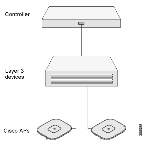
The following illustration shows the preinstallation configuration setup:

Perform the following steps:

Before you begin

Ensure that the Cisco Controller Distribution System (DS) port is connected to the network. Use the procedure for CLI or GUI as described in the release appropriate Cisco Catalyst 9800 Series Wireless Controller Software Configuration Guide.
  • Enable Layer 3 connectivity between APs, Cisco Controller Management, and AP-Manager interface.

  • Configure the switch to which your AP has to attach. See the Cisco Wireless Controller Configuration Guide for the release you are using, for additional information.

  • Configure the Cisco Catalyst 9800 Series Wireless Controller as the primary so that new APs always join it.

  • Ensure that the DHCP is enabled on the network. The AP must receive its IP address through DHCP.


    Note


    An 802.11ax AP is assigned an IP address from the DHCP server only if a default router (gateway) is configured on the DHCP server (enabling the AP to receive its gateway IP address) and the gateway ARP is resolved.
  • CAPWAP UDP ports must not be blocked in the network.

  • The AP must be able to find the IP address of the controller. This can be accomplished using DHCP, DNS, or IP subnet broadcast. This guide describes the DHCP method to convey the controller IP address. For other methods, see the product documentation.


    Note


    The AP requires a multi-gigabit Ethernet (5 Gbps) link to prevent the Ethernet port from becoming a bottleneck for traffic.

Procedure


Step 1

Power the AP using supported power source.

  • As the AP attempts to connect to the controller, the LED cycles through a green, red, and off sequence, which can take up to five minutes.

    Note

     
    If the AP remains in this mode for more than five minutes, the AP cannot find the primary Cisco Catalyst 9800 Series Wireless Controller. Check the connection between the AP and the Cisco Catalyst 9800 Series Wireless Controller and be sure that they are on the same subnet.
  • If the AP shuts down, check the power source.

  • After the AP finds the Cisco Catalyst 9800 Series Wireless Controller, it attempts to download the new operating system code if the AP code version differs from the Cisco Catalyst 9800 Series Wireless Controller code version. While this is happening, the Status LED blinks blue.

If the operating system download is successful, the AP reboots.

Step 2

(Optional) Configure the AP. Use the controller CLI, GUI, or Cisco DNA Center to customize the access point-specific 802.11ax network settings.

Step 3

If the preinstallation configuration is successful, the Status LED is green, indicating normal operation. Disconnect the AP and mount it at the location at which you intend to deploy it on the wireless network.

Step 4

If your AP does not indicate normal operation, turn it off and repeat the preinstallation configuration.

Note

 
When you are installing a Layer 3 access point on a subnet that is different from the Cisco Catalyst 9800 Series Wireless Controller, ensure the following setup is configured:
  • A DHCP server is reachable from the subnet on which you plan to install the AP.

  • The subnet has a route back to the controller.

  • This route has destination UDP ports 5246 and 5247 open for CAPWAP communications.

  • The route back to the primary, secondary, and tertiary controller allows IP packet fragments.

  • If address translation is used, the access point and the controller have a static 1-to-1 NAT to an outside address. Port Address Translation is not supported.


Preinstallation Checks and Installation Guidelines

Before you mount and deploy your access point, we recommend that you perform a site survey (or use the Site Planning tool) to determine the best location to install your access point.

You should have the following information about your wireless network available:

  • Access point locations

  • Access point mounting options: To a vertical or horizontal wall or a pole

  • Access point power options: Use either of the following options to power the AP:

    • DC power input

    • Cisco-approved power injector

    • 802.3at (PoE+), 802.3bt, and Cisco Universal PoE (Cisco UPOE)

  • Operating temperature: -40° to +158°F (-40° to +70°C) with solar load and still air.

  • Console access using the console port

    We recommend that you use a console cable that is one meter or less in length.


    Note


    The AP may face issues while booting if you use an unterminated console cable (not plugged into any device or terminal) or a console cable that is more than one meter in length.

We recommend that you make a site map showing access point locations so that you can record the device MAC addresses from each location and return them to the person who is planning or managing your wireless network.

Installing the Catalyst IW9167E with Stadium Antenna

You can install the access point on a wall or ceiling (must be a flat surface) or on a pole with a minimum diameter of 2 inches (5.08 cm) and a maximum diameter of 5 inches (12.7 cm).


Note


Install the access point with the panel level that is aligned to the horizon or at lower angles. You must never point the access point upwards toward the sky to maintain compliance with radio emission regulations.

Procedure


Step 1

Decide on a mounting location.

See Deciding on a Mounting Location.

Step 2

Ensure that you have the required tools and fasteners ready.

See Required Tools and Equipment.

Step 3

Proceed with mounting the access point.

When mounting the access point:

  1. Assemble the bracket hardware.

  2. Connect the access point and the bracket to the mounting surface.

  3. Connect the access point to the ground using the included ground screw and electrical joint compound.

  4. Adjust the access point orientation.

The mounting options available are:


Deciding on a Mounting Location

The antenna should be mounted clear of any obstructions to the side or front of the enclosure, which contains the radiating elements. Remember to aim this antenna at the intended coverage area. Therefore, you should mount the antenna and adjust it to achieve the desired mechanical tilt.


Caution


As with all the outdoor installations, you must install the antenna with cables exiting downward which helps prevent water from accumulating around the cable exit points.

Required Tools and Equipment


Warning


Statement 1071—Warning Definition

IMPORTANT SAFETY INSTRUCTIONS

Before you work on any equipment, be aware of the hazards involved with electrical circuitry and be familiar with standard practices for preventing accidents. Read the installation instructions before using, installing, or connecting the system to the power source. Use the statement number at the beginning of each warning statement to locate its translation in the translated safety warnings for this device.

SAVE THESE INSTRUCTIONS


Warning


Statement 1090—Installation by Skilled Person

Only a skilled person should be allowed to install, replace, or service this equipment. See statement 1089 for the definition of a skilled person.

There are no serviceable parts inside. To avoid risk of electric shock, do not open.


Warning


Statement 1089—Instructed and Skilled Person Definitions

An instructed person is someone who has been instructed and trained by a skilled person and takes the necessary precautions when working with equipment.

A skilled person or qualified personnel is someone who has training or experience in the equipment technology and understands potential hazards when working with equipment.

There are no serviceable parts inside. To avoid risk of electric shock, do not open.


Warning


Statement 445—Connect the Chassis to Earth Ground

To reduce the risk of electric shock, connect the chassis of this equipment to permanent earth ground during normal use.


Caution


The fasteners and the mounting surface should be capable of maintaining a minimum pullout force of 150 pounds (68 kg) to support the weight of the antenna and bracket, along with the potential wind loading on the antenna.

Caution


The pole or mast must be rigid enough to hold the weight of the antenna along with the associated forces produced by wind loads. Also, the pole or mast must be structurally strong enough to withstand the clamping force of the hose clamps.

Before you mount the antenna, go through the supported mounting procedures and ensure that you have all tools and fasteners mentioned therein ready. The following is a general list of fasteners and tools not included in the antenna and brackets kit:

  • To mount the antenna on a wall or ceiling, you need four mounting M8 screws or bolts and wall anchors.

  • To mount the antenna on a pole or mast, you may need either or both of these supplies:

    • A slotted screwdriver or a wrench to tighten the screws on the hose clamps

    • A Hex key to tighten set screws

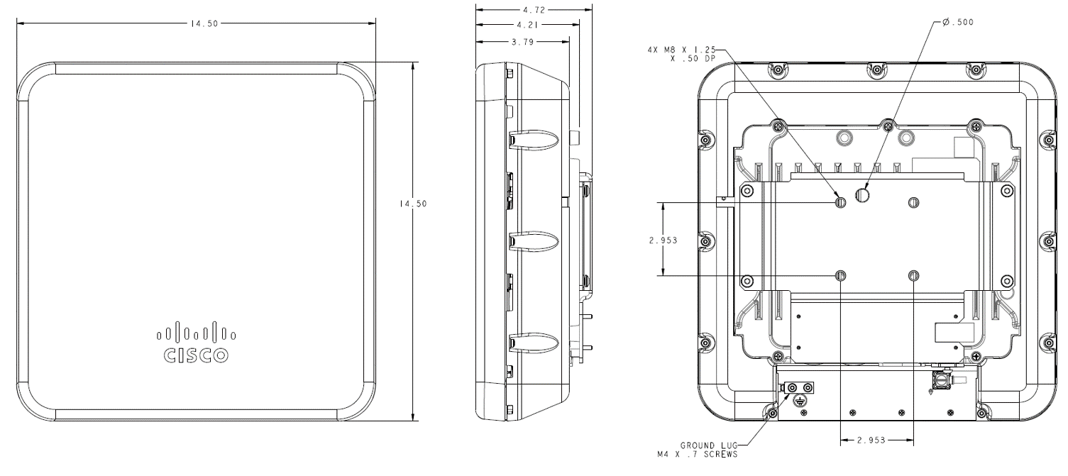
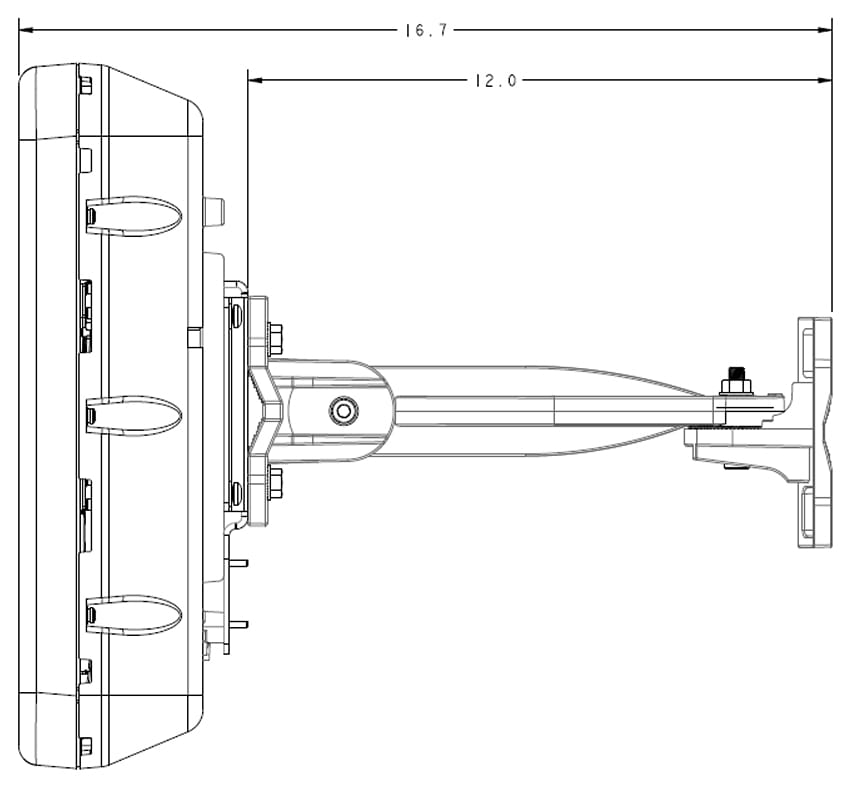
Dimensions of the Antenna and Bracket

The dimensions noted in the following illustrations are all in millimeters, unless noted otherwise.

Figure 1. Dimensions of the Antenna with Mounting Bracket

measurements in inches (in).

The pressure vent is located at the side of the antenna.

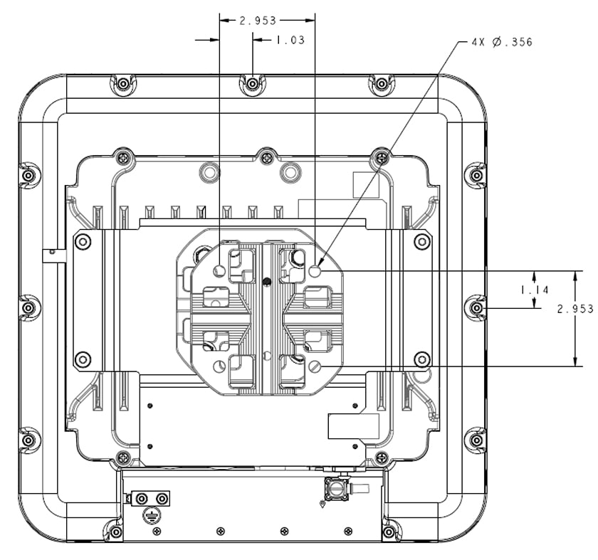
Figure 2. Locations of Screw Holes at the Back of the Antenna


The mounting hole location on the articulating mount flange. The flange supports VESA 75 mount pattern.

Figure 3. Assembly view

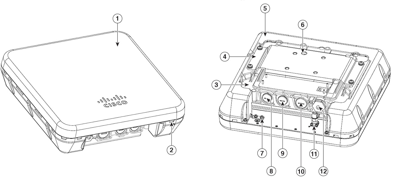
1

Stadium Antenna

7

Ground lug

2

Drain hole

8

DC IN port (PG 13.5)

3

Cisco Catalyst IW9167E-x AP

9

Ethernet/PoE port (PG 13.5)

4

Bracket adapter plate

10

SFP port (M25)

5

Shroud

11

GNSS port

6

Safety strap hole

12

Console port (M25)


Note


Removing back shroud will void product warranty.
Figure 4. Locations of the Screw Holes on the Articulating Mount Flange


1

Pole / Mast mounting set screw holes

2

Slotted holes for hose clamps

Mount Using Articulating Bracket on a Wall or Ceiling


Note


When using the articulating bracket, the antenna assembly and mounting hardware must be tethered to a secure mounting surface using the tether hole on the antenna assembly. The mounting kit does not include the tether strap.
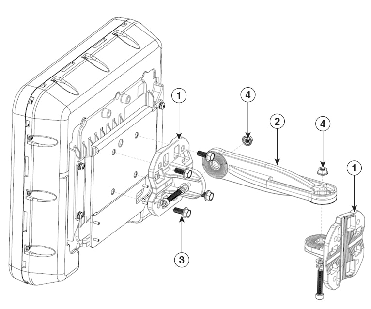
Figure 5. Exploded View of Antenna and Bracket Hardware Assembly


Item #

Mounting Bracket Kit

Quantity

Tightening Values

1

Mounting flange

2

2

Mounting arm

1

3

M8 x20 screws

4

20.0 +/- 1.0 Nm

4

M8 nut

2

25.0 +/- 1.0 Nm

Figure 6. Close-Up View of the Azimuth and Elevation-Adjustment Pivots


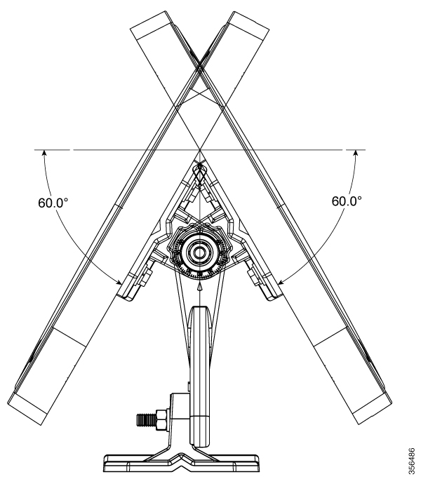
Figure 7. Azimuth Adjustment


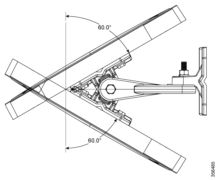
Figure 8. Elevation Adjustment


Procedure


Step 1

Determine the mounting location for the antenna.

Step 2

Attach one of the mount flanges to the wall or ceiling using four M8 screws through the holes in the bracket.

Note

 
The mounting kit does not include the M8 screws for securing the bracket to the mounting surface.

Step 3

Attach the other mount flange to the back of the antenna using four M8 screws through the holes in the bracket.

Tighten the screws to 20.0 +/- 1.0 Nm torque.

Step 4

Assemble the mounting arm to the flanges.

Use a wrench to tighten all screws and nuts. See Exploded View of Antenna and Bracket Hardware Assembly.

Step 5

Orient the antenna correctly so that the antenna cable exits downwards.

Use a wrench to loosen or tighten the fasteners at the azimuth and elevation- adjustment pivots.

Step 6

Adjust the azimuth (side-to-side position) and elevation (up-and-down position) of the antenna.

Loosen the adjustment pivot nuts slightly to allow for adjustment. Use the azimuth and elevation markings on the articulating mounting arm and the flange brackets as a guide. See Close-Up View of the Azimuth and Elevation-Adjustment Pivots. You may adjust the azimuth angle up to ±60 degrees, see Azimuth Adjustment, and elevation up to ±60 degrees see Elevation Adjustment.

Step 7

After adjusting the antenna position, tighten the pivot nuts.

Tighten all nuts at the pivot points to 25.0 +/- 1.0 Nm torque.

Step 8

Connect the Ethernet cable to the antenna using the termination kit.

Step 9

Connect the antenna to the building ground using the grounding kit.


Mount Using Articulating Bracket on a Pole or Mast

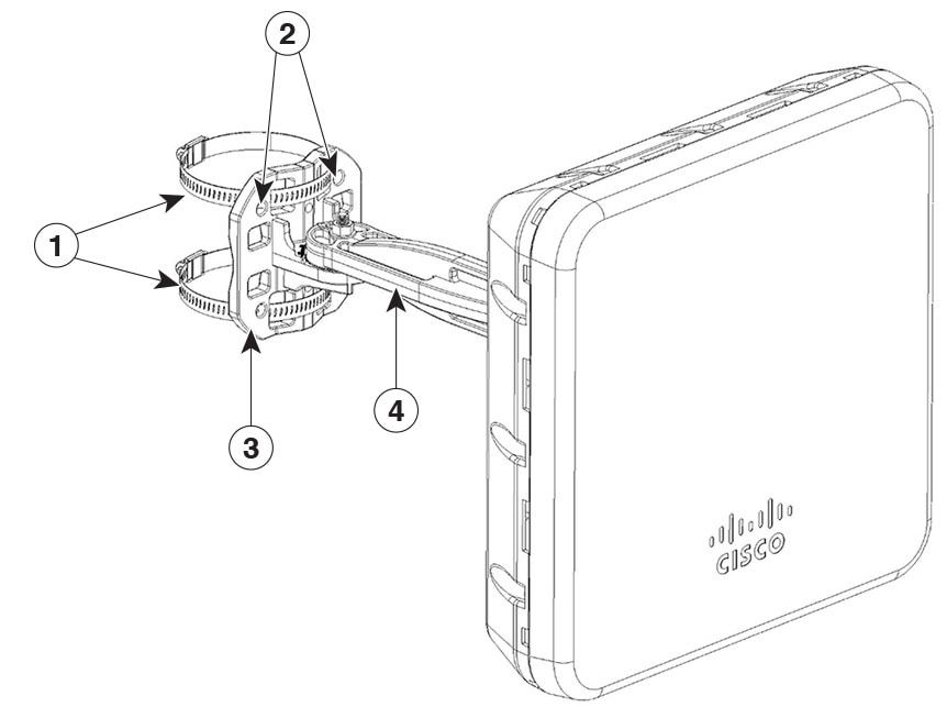
Figure 9. Antenna Bracket Hose Clamp Assembly for Pole Mounting

1

Worm-gear-type hose clamp (50–135mm) for mounting the assembly on a pole or mast

3

Articulating mount flange that is fastened to the pole or mast using hose clamps

2

Screws holes to mount the assembly to a wall.

4

Articulating mount arm

Before you begin


Note


The pole or mast must be rigid enough to hold the weight of an antenna along with the associated forces produced by wind loads. In addition, the mast must be structurally strong enough to withstand the clamping force of the hose clamps.

Procedure


Step 1

Determine the mounting location for the antenna on the pole or mast.

Step 2

Position and mount the mounting flange bracket onto the pole or mast using the hose clamps provided in the kit.

The hose clamps should pass through the slots on the free mounting flange bracket.

Step 3

Tighten the hose clamps and set screws until the antenna is fully secure on the mast.

Then, adjust the antenna to its final position. Then, use a slotted screwdriver to tighten the screws on the hose clamps.

Step 4

Attach the other mount flange through the holes in the bracket to the back of the antenna using four M8 screws.

The mounting kit includes the mounting flange and M8 screws. Tighten the screws to 20.0 +/- 1.0 Nm torque.

Step 5

Assemble the mounting arm to the flanges.

Use a wrench to tighten all screws and nuts.

Step 6

Ensure that the antenna cannot rotate about the mast.

Step 7

Adjust the azimuth (side-to-side position) and the antenna’s elevation (up-and-down position).

Loosen the adjustment pivot nuts slightly to allow for adjustment.

You can use the azimuth and elevation markings on the articulating mounting arm and the flange brackets as a guide. See Close-Up View of the Azimuth and Elevation-Adjustment Pivots. You can adjust the azimuth angle up to ±60 degrees, see Azimuth Adjustment, and elevation up to ±60 degrees see Elevation Adjustment.

Step 8

After adjusting the antenna position, tighten all nuts at the pivot points to 25.0 +/- 1.0 Nm torque.

Step 9

Connect the Ethernet cable to the antenna using the termination kit.


Grounding the Access Point

In all installations, after mounting the access point, you must properly ground the unit before connecting power cables.


Warning


Statement 1024—Ground Conductor

This equipment must be grounded. To reduce the risk of electric shock, never defeat the ground conductor or operate the equipment in the absence of a suitably installed ground conductor. Contact the appropriate electrical inspection authority or an electrician if you are uncertain that suitable grounding is available.


Warning


Statement 1074—Comply with Local and National Electrical Codes

To reduce risk of electric shock or fire, installation of the equipment must comply with local and national electrical codes.


The access point is shipped with a grounding kit.

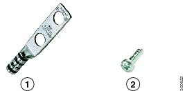
Figure 10. Access Point Grounding Kit Contents

1

Grounding lug

2

Screws x 2, M4 x 6mm


Note


The grounding kit also includes the oxide inhibitor, which is contained in a tube.

To ground the access point:

Procedure


Step 1

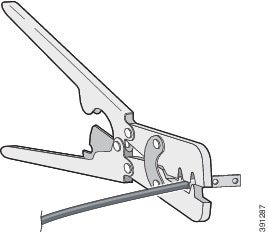
Use a crimping tool to crimp a 6-AWG (13.3 mm2) ground wire (not included in the grounding kit) to the ground lug.

Step 2

Connect the supplied ground lug to the access point ground connection point using the supplied screws.

Apply supplied oxide inhibitor between the ground lug and the access point ground connection.

1

AP ground connection point

Step 3

Tighten the screws to 20-25 inch-lbs of torque.

Step 4

If necessary, strip the other end of the ground wire and connect it to a reliable earth ground such as a grounding rod or appropriate ground point on a grounded pole.

Length of the ground cable should not exceed 1 meter, and 0.5 meter is preferred.

Use supplied oxide inhibitor on the grounded interface.


Powering the Access Point

The AP supports these power sources:

  • DC power – 24–48 VDC

  • Power-over-Ethernet (PoE)

The AP can be powered via the PoE input from an inline power injector or a suitably powered switch port. Depending on the configuration and regulatory domain, the required power for full operation is 802.3bt or UPOE.

For more information, see Power Sources.

Power Sources

The Cisco Catalyst IW9167 Series Access Points supports the following power sources:

  • DC power input: 24 to 48 Vdc, 2.0 to 0.9 A


    Note


    Use DC cable with only No. 18 AWG or larger.
  • Power over Ethernet (PoE) input: 42.5 to 57 Vdc, 1.0 to 0.7 A

    802.3at (PoE+), 802.3bt (PoE++), Cisco Universal PoE (Cisco UPOE). For more information, see Powering the Access Point.


    Note


    Use CAT5e or better Ethernet cable with only No. 24 AWG or larger telecommunication line cord.

Warning


Statement 1033—Safety Extra-Low Voltage (SELV)—IEC 60950/ES1–IEC 62368 DC Power Supply

To reduce the risk of electric shock, connect the unit only to a DC power source that complies with the SELV requirements in the IEC 60950-based safety standards or the ES1 requirements in the IEC 62368-based safety standards.


Power Adapters

The Cisco Catalyst IW9167E Heavy Duty Access Point supports the following DC power adapters:

  • PID: IW-PWRADPT-MFIT4P=: Operating: -40°C to +65°C, 60W.

  • PID: IW-PWRADPT-MFIT4IN=: Operating: -40°C to +65°C, 60W.

Power Injectors

The Cisco Catalyst IW9167E Heavy Duty Access Point supports the following power injectors:

  • IW-PWRINJ-60RGDMG=: Operating: -40°C to +70°C. Power derating of 60W at 70°C, and 65W at 65°C. Supports 100M/1G/2.5G/5G/10G rates.

  • AIR-PWRINJ-60RGD1=: Operation: -40°C to +50°C, 60W. Supports 10M/100M/1G rates.

  • AIR-PWRINJ-60RGD2=: Operation: -40°C to +50°C, 60W. Supports 10M/100M/1G rates.


Caution


When the AP is installed outdoors or in a wet or damp location, the AC branch circuit powering the AP should be provided with ground fault protection (GFCI), as required by Article 210 of the National Electrical Code (NEC).

Ethernet (PoE) Ports

The AP supports an Ethernet uplink port (also for PoE-IN). The Ethernet cable uses an RJ-45 connector (with weatherproofing) is used to send and receive Ethernet data and optionally supply inline power from the power injector or a suitably powered switch port.


Tip


The AP senses the Ethernet and power signals, and automatically switch internal circuitry to match the cable connections.

Power Feature Matrix

The following table provides the AP power feature matrix.

Table 1. Catalyst IW9167EH Access Point Power Feature Matrix

Power Input

2.4 GHz Radio

dBm Per Path

5 GHz Radio

dBm Per Path

6 GHz Radio

dBm Per Path

Aux Radio

GNSS

mGig Eth

SFP

24-48V

4x4

24

4x4

24

4x4

17

Yes

Yes

max 5G

Yes

802.3bt/ UPOE

4x4

24

4x4

24

4x4

17

Yes

Yes

max 5G

Yes

802.3at

2x2

23

2x2

23

2x2

17

Yes

Yes

max 1G

Yes/1G

Connecting a Power Injector

The AP supports the following power injectors:

Table 2. Supporting Power Injectors

Power Source

Description

AIR-PWRINJ-60RGD1=

60W rated outdoor power injector, with North America AC plug

AIR-PWRINJ-60RGD2=

60W rated outdoor power injector, global version without AC plug

IW-PWRINJ-60RGDMG=

60W rated outdoor power injector, 5GE

The power injector provides DC voltage to the AP over the Ethernet cable and supports a total end-to-end Ethernet cable length of 100 m (328 ft) from the switch to the AP.

When an optional power injector powers your AP, follow these steps to complete the installation:

Procedure


Step 1

Before applying PoE to the AP, ensure that the AP is grounded (see Grounding the Access Point).

Step 2

Connect a CAT5e or better Ethernet cable from your wired LAN network to the power injector.

Note


The installer is responsible for ensuring that powering the AP from this type of power injector is allowed by local and/or national safety and telecommunications equipment standards.

Step 3

Ensure that the antennas are connected, and that ground is attached to the AP before you apply power to the AP.

Step 4

Connect a shielded outdoor-rated Ethernet (CAT5e or better) cable between the power injector and the AP's PoE-in connector.

Step 5

Connect the Ethernet cable to the AP PoE-In port.


Connecting to the DC Power Port Using Cable Gland

Follow these steps to connect to the DC power port using Cable Gland:

Procedure


Step 1

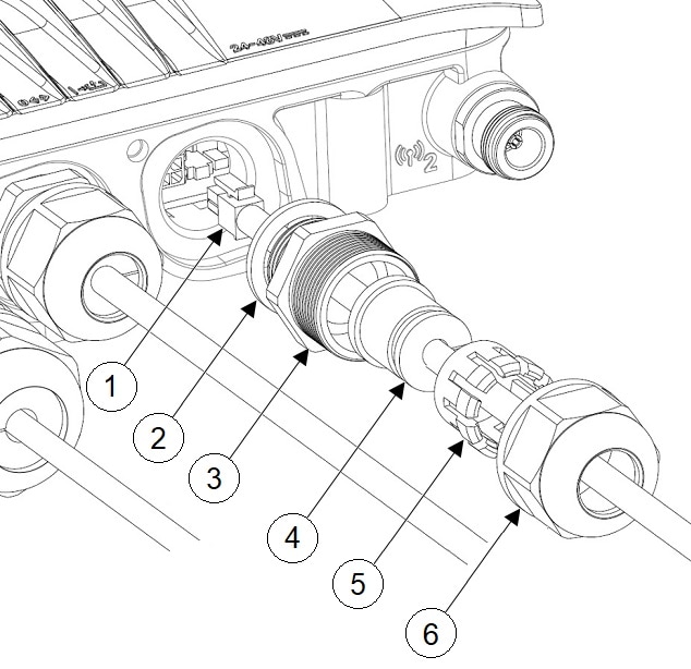
Disassemble PG13 cable gland and slide parts over DC cable in the order shown in the following figure:

1

DC cable

4

Grommet

2

Gasket

5

Ferrule

3

PG13 body

6

Clamp nut

Step 2

Plug 4P connector cable into the DC connector in the chassis.

Step 3

Thread the PG13 body (with gasket) into the chassis.

Step 4

Insert the grommet into the ferrule, and press it into the PG13 body.

Step 5

Tighten the clamp nut onto the PG13 body until the grommet compresses onto the DC cable.

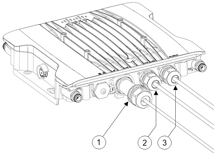
1

SFP port connected using cable gland

2

RJ-45 port connected using cable gland

3

DC power port connected using cable gland


Connecting DC Power Port Using M12 Adapter

Follow these steps to connect to the DC power port using M12 adapter:

Before you begin

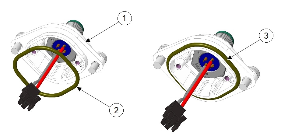
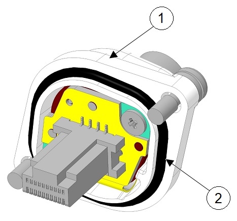
O-rings are shipped separately from the M12 adapter. You need to place the o-ring on the adapter before installing the M12 adapter to the chassis.

Figure 11. Installing O-ring on the M12 Adapter

1

M12 adapter

2

O-ring

3

O-ring installed on M12 adapter

Procedure


Step 1

Ensure the O-ring is on the M12-PWR adapter.

Step 2

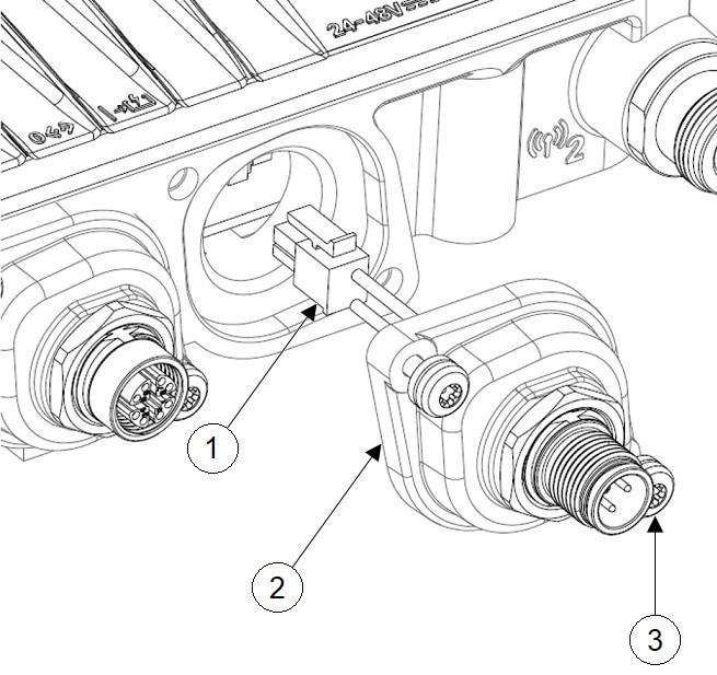
Plug in DC connector into the chassis. Press M12-PWR adapter onto the chassis, and ensure that the wires are not pinched.

1

DC connector

3

Captive screws

Tighten with 15-20 in-lbs torque.

2

M12-PWR adapter

Step 3

Tighten the M12-PWR adapter captive screws into the chassis.

Tighten the M12 captive screws with 15-20 in-lbs torque.

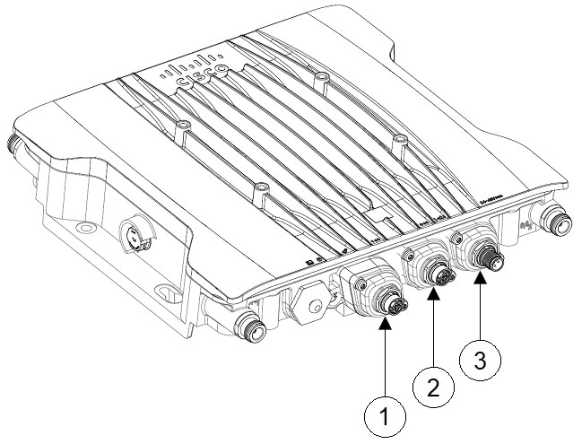
1

SFP port connected using M12 adapter

3

DC power port connected using M12 adapter

2

RJ-45 port connected using M12 adapter


Connecting Data Cables

This AP supports data connections through the Ethernet port and the Small Form-factor Pluggable (SFP) port.

If you are using the SFP port to deliver data through a fiber-optic cable, the AP must be powered by DC power, power adapter, PoE+ power source, or a power injector.

Connect using an Ethernet Cable

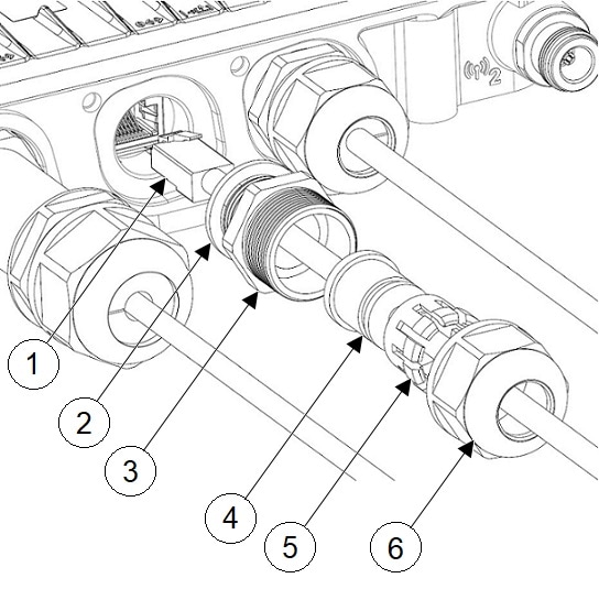
Connecting to the RJ-45 Port Using Cable Gland

Follow these steps to connect to the RJ-45 port using Cable Gland:

Procedure


Step 1

Disassemble PG13 cable gland and slide parts over RJ-45 cable in the order that is shown in the following figure:

1

RJ-45 cable

4

Grommet

2

Gasket

5

Ferrule

3

PG13 body

6

Clamp nut

Step 2

Plug the RJ-45 cable into the RJ-45 connector in the chassis.

Step 3

Thread the PG13 body (with gasket) into the chassis.

Step 4

Insert the grommet into the ferrule, and press it into the PG13 body.

Step 5

Tighten the clamp nut onto the PG13 body until the grommet compresses onto the RJ-45 cable.

1

SFP port connected using cable gland

2

RJ-45 port connected using cable gland

3

DC power port connected using cable gland


Connecting to the RJ-45 Port Using M12 Adapter

Follow these steps to connect to the RJ-45 port using M12 adapter:

Procedure


Step 1

Ensure the O-ring is on the M12 adapter.

1

M12 adapter

2

O-ring

Step 2

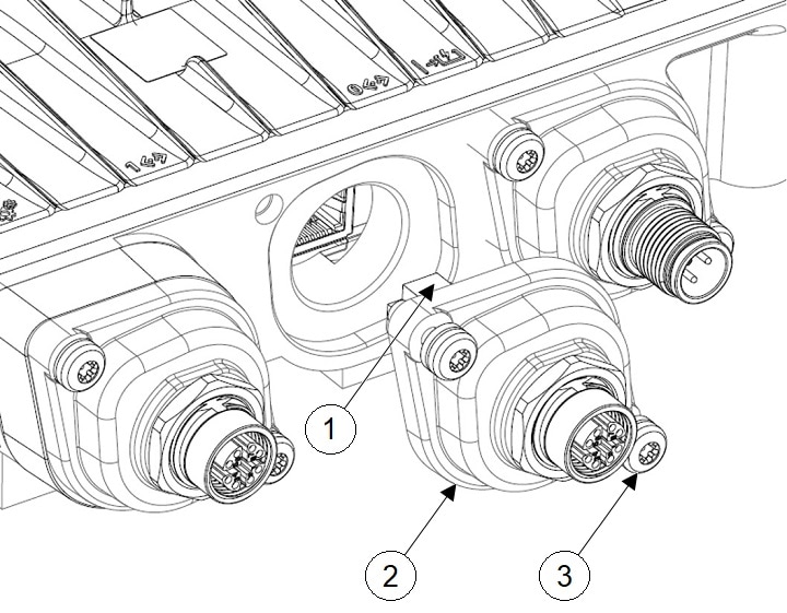
Align the RJ-45 tab with the RJ-45 connector in the chassis, and plug the M12 adapter into the chassis.

1

RJ-45 tab

3

Captive screws

Tighten with 15-20 in-lbs torque.

2

M12-RJ45 adapter

Step 3

Tighten the M12 adapter captive screws into the chassis.

1

SFP port connected using M12 adapter

3

DC power port connected using M12 adapter

2

RJ-45 port connected using M12 adapter


Connect using a Fiber-Optic Cable

Connecting to SFP Port Using Cable Gland

Follow these steps to connect to the SFP port using cable gland:


Note


Copper SFP or Fiber SFP will be detected by the system only after a power cycle.

Procedure


Step 1

Insert the fiber SFP into the chassis.

Step 2

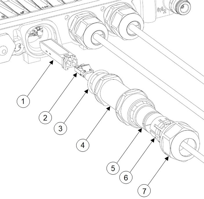
Disassemble the fiber adapter and slide parts over fiber cable in the order shown in the following figure:

1

Fiber SFP

5

Grommet

2

Fiber cable

6

Ferrule

3

O-Ring

7

Clamp nut

4

Adapter body

Step 3

Plug the fiber cable into the SFP.

Step 4

Thread the adapter body (with O-Ring) into the chassis.

Step 5

Insert the grommet into the ferrule, and press it into the adapter body.

Step 6

Tighten the clamp nut onto the adapter body until the grommet compresses onto the fiber cable.

1

SFP port connected using cable gland

2

RJ-45 port connected using cable gland

3

DC power port connected using cable gland


Using M12 Adapter on SFP Port

M12 adapter can be used only with a copper SFP and not supported with fiber SFP.


Note


Copper SFP or Fiber SFP will be detected by the system only after a power cycle.

Follow these steps to connect M12 adapter to the SFP port:

Procedure


Step 1

Insert the copper SFP in the chassis.

Step 2

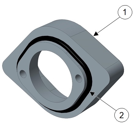
Ensure the O-rings are on the M12 adapter and spacer.

1

M12 adapter

2

O-ring

1

Spacer

2

O-ring

Step 3

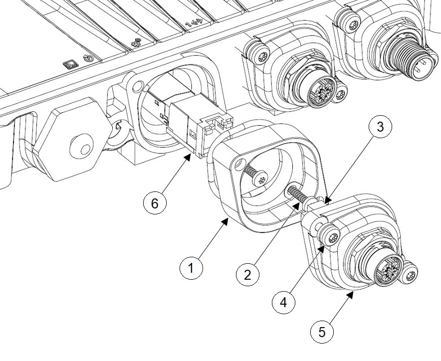
Attach the spacer to the chassis with the screws provided (2 in the following figure).

1

Spacer

4

Captive screws

Tighten with 15-20 in-lbs torque.

2

Spacer screws, M3

Tighten with 8-10 in-lbs torque minimum or until it sits flush.

5

M12-RJ45 adapter

3

RJ-45 tab

6

Copper SFP

Step 4

Align the RJ-45 tab with the RJ-45 connector in the chassis and plug the M12 adapter into the chassis

Step 5

Tighten the M12 adapter captive screws into the chassis (4 in the above figure).

1

SFP port connected using M12 adapter

3

DC power port connected using M12 adapter

2

RJ-45 port connected using M12 adapter