About Cisco Catalyst IW9167E for Hazardous Location Access Point

Cisco Catalyst IW9167E for Hazardous Location Access Point

The Cisco Catalyst IW9167EH for Hazardous Location Access Point is a tri-band 802.11ax (Wi-Fi 6) AP that provides reliable wireless connectivity for mission-critical applications as organizations automate processes and operations. It can operate as Wi-Fi 6 or Cisco Ultra-Reliable Wireless Backhaul (Cisco URWB). Wi-Fi 6 technology brings higher density, higher throughput, more channels, power efficiency, and improved security in industrial or outdoor locations. Cisco URWB provides ultra-reliable wireless connectivity for moving assets or to extend the network where running fiber isn’t feasible or is too costly.

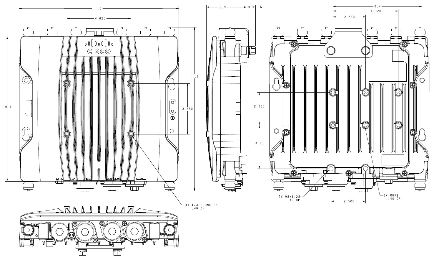
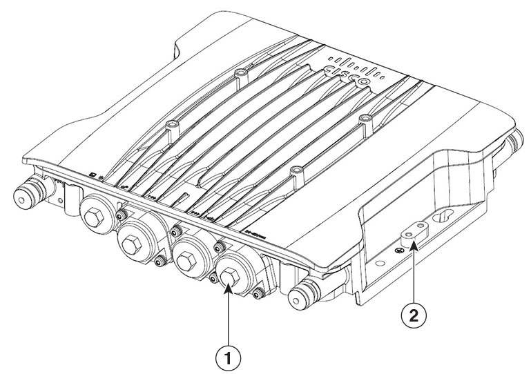
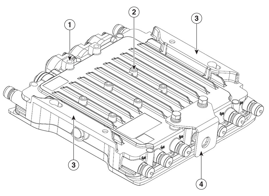
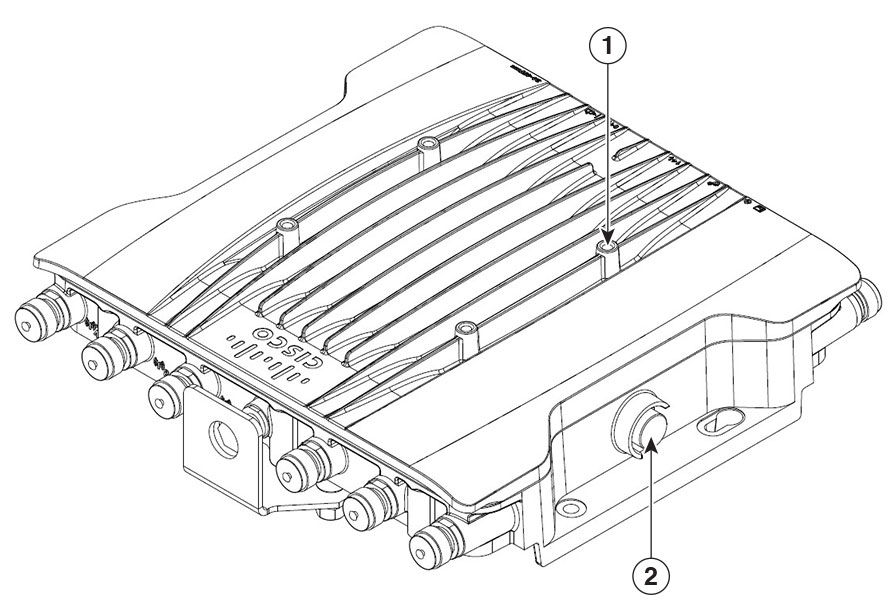
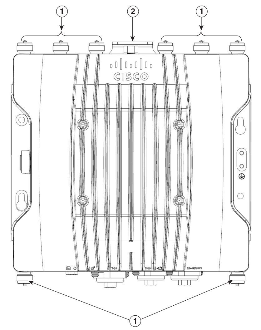
The Cisco Catalyst IW9167E Heavy Duty Access Point comes with three 4x4 radios, in a heavy-duty design that is IP67 rated, and packed with advanced features.

The Cisco Catalyst IW9167E Heavy Duty Access Point Series includes the following hardware model:

  • Catalyst IW9167EH-x-HZ—Certified for installation in hazardous environments.

x denotes the regulatory domain: A, B, E, F, Q, Z, or ROW.

A full listing of the AP's features and specifications is provided in the Cisco Catalyst IW9167E Heavy Duty Access Point Data Sheet.

Cisco Catalyst IW9167E for Hazardous Location Access Point Features

This Access Point is supported on Cisco Catalyst 9800 wireless controller-based products, and has the following features:

  • 2 GB DDR4 memory, 1 GB NAND Flash

  • Tri-radio, dual band support: 2.4-GHz Slot 0, 5-GHz Slot 1, and 5/6 GHz Slot 2

  • 4 x 4 MIMO with up to four spatial streams

  • 8 x N-type female connectors for Wi-Fi, 1x TNC female for GNSS, multi-protocol loT radio, Aux radio, Barometer

  • Bluetooth Low Energy (BLE) radio enables IoT use cases such as location tracking and way finding.

  • Operation mode—Cisco URWB, WGB, or AP

  • 1 x multi-Gigabit (mGig) copper Ethernet port (supporting PoE, including IEEE 802.3at/bt, Cisco UPoE, 100 Mbps/1 Gbps/2.5 Gbps/5 Gbps)

  • 1 x SFP interface—supports up to 10 Gbps


    Note


    For 10G SFP fiber module, Cisco PID SFP-10G-LR10-I has guaranteed performance with the Catalyst IW9167E access point.


  • Dual power input options—PoE-in and 24–48VDC

  • Water and dust resistance—IP 66/67

  • Hardened for shock, vibration, and extreme temperatures

  • Operating temperature:

    • -40°C ≤ Ta ≤ 70°C without solar loading

    • Support cold start at -40°C and extend working at -50°C.

Physical Specifications

The dimensions noted in the following illustrations are all in inches, unless noted otherwise

1

Port Access Plugs (3x)—M25 x1.5, 1/2"/ 13mm Hex

2

Ground Lug Location

The AP enclosure hardpoints for mounting.

1

M8 Hardpoints (2x)—M8x1.25, 0.40" depth

3

Mounting Flange

2

M6 Hardpoints (6x)—M6x1, 0.40" depth

4

Impact Protection Bracket


Note


When GNSS Antenna is used, install the TNC connector L shape metal guard.
A pressure vent is provided to maintan pressure within the enclosure.

1

¼-20 Hardpoints (4x)—1/4-20UNC-2B, 0.40" depth

2

Pressure vent

Connectors and Ports

The following figures show the available ports and connectors on the AP.

Figure 1. Catalyst IW9167EH-HZ Ports

1

Antenna ports

2

GNSS port

Figure 2. Catalyst IW9167EH-HZ Connectors

1

Console port (RJ-45)

4

SFP (copper) 100M/1000M/10G Multigigabit Ethernet or SFP (fiber) 1G/10G

2

Reset button

For information on how to use the Reset button, see Using the Reset Button.

5

100M/1000M/2.5G/5G Multigigabit Ethernet (RJ-45) auto-sensing PoE+ in (802.3at/bt), UPOE-in

3

Status LED

6

DC power input (micro-fit)


Note


  • The SFP/RJ-45/DC power ports used cable should be rated ≥ 82°C

  • The M25 I/O port Caps (RJ-45 Console port, SFP port, Ethernet (PoE) Ports or DC power in port) must be installed when the ports are not in use. Tighten with maximum torque range: 35 to 40 lbf.in.


4-Pin Micro-Fit Connector for DC Power

The following figures show the 4-pin Micro-Fit connector for DC power.

Figure 3. Mating Connector: Molex Micro-Fit 43025-0400
Figure 4. Mating Connector Front View

Molex Micro-Fit Pin

Assignment

Pin 1

Black ( - Negative Terminal)

Pin 2

Not assigned

Pin 3

White (+ Positive Terminal)

Pin 4

Not assigned

Power Sources

The Cisco Catalyst IW9167 Series Access Points supports the following power sources:

  • DC power input: 24 to 48 Vdc, 2.0 to 0.9 A


    Note


    Use DC cable with only No. 18 AWG or larger.
  • Power over Ethernet (PoE) input: 42.5 to 57 Vdc, 1.0 to 0.7 A

    802.3at (PoE+), 802.3bt (PoE++), Cisco Universal PoE (Cisco UPOE). For more information, see Powering the Access Point.


    Note


    Use CAT5e or better Ethernet cable with only No. 24 AWG or larger telecommunication line cord.

Caution


Do not use a third-party power adapter or PoE injector with the Catalyst IW9167EH-HZ AP.

Warning


Statement 1033—Safety Extra-Low Voltage (SELV)—IEC 60950/ES1–IEC 62368 DC Power Supply

To reduce the risk of electric shock, connect the unit only to a DC power source that complies with the SELV requirements in the IEC 60950-based safety standards or the ES1 requirements in the IEC 62368-based safety standards.


Ethernet (PoE) Ports

The AP supports an Ethernet uplink port (also for PoE-IN). The Ethernet cable uses an RJ-45 connector (with weatherproofing) is used to send and receive Ethernet data and optionally supply inline power from the power injector or a suitably powered switch port.


Tip


The AP senses the Ethernet and power signals, and automatically switch internal circuitry to match the cable connections.

Data Connectivity

Ethernet (PoE) Ports

The AP supports an Ethernet uplink port (also for PoE-IN). The Ethernet uplink port on the AP uses an RJ-45 connector (with weatherproofing) to link the AP to the 100BASE-T, 1000BASE-T, 2.5G BASE-T, or 5G BASE-T network.

The Ethernet cable must meet the Hazadous Location use requirements, that is, the cable should be armoured or in-conduit Category 5e (CAT 5e) or better cable, Category 6A (CAT 6A) cable is needed for 5G rate.


Tip


The AP senses the Ethernet and power signals, and automatically switch internal circuitry to match the cable connections.

SFP Option


Warning


Statement 1008—Class 1 Laser Product

This product is a Class 1 laser product.


The factory-orderable fiber option provides a fiber input and output capability. Fiber data is transmitted and received over a single or dual-strand fiber cable, depending on the SFP, which is connected to the access point using these SFP modules:

Table 1. Supported SFP Modules

PID

Distance

Fiber/Cable

Operating Temperature Range

GLC-SX-MM-RGD=

220-550m

MMF

IND

GLC-LX-SM-RGD=

550m/10km

MMF/SMF

IND

GLC-T-RGD=1

100m

CAT 5e

IND

SFP-10G-LR10-I

10km

SMF

IND

SFP-10G-T-X2

30m@10Gbps

CAT 6A/CAT 7

EXT

SFP-10G-SR-I=

300m

OM3

IND

1 GLC-T-RGD= supports only 1000BASE-T connection.
2 SFP-10G-T-X is not in supported in Cisco IOS XE Release 17.9.3.

Note


SFP modules are not hot-swappable. When you plug and unplug the SFP module, a manual reload of the AP is required.


Client data is passed to the network controller through the fiber connection via a fiber-capable switch or controller. Configuration information can be found in the controller configuration guide of the switch or controller you are using.

Antennas and Radios

The Catalyst IW9167EH access point has eight N-type female connectors to support multiple antenna options, such as the self-identifying antennas (SIA) on designated three SIA ports, dual-band antennas, and single-band antennas.

Supported External Antennas

The following figure shows the antenna ports of the Catalyst IW9167EH-x-HZ access point.


Note


  • Antenna caps must be installed when an antenna is not in use. Tighten with maximum torque range: 2.5 lbf.in.

  • Catalyst IW9167EH-x-HZ AP does not support third-party antennas.


Figure 5. Catalyst IW9167EH-HZ Access Point Antenna Ports

1

Port 1

Supports 2.4 GHz radio in 4x4, 2x2, or 1x1 mode. Supports 5 GHz radio in 4x4 mode. Supports SIA.

2

Port 2

Supports 2.4 GHz radio in 4x4, 2x2 mode. Supports 5 GHz radio in 4x4 mode.

3

Port 3

Supports 2.4 GHz radio in 4x4 mode. Supports 5 GHz radio in 4x4,2x2 mode.

4

Port 4

Supports 2.4 GHz radio in 4x4 mode. Supports 5 GHz radio in 4x4, 2x2, or 1x1 mode. Supports Bluetooth Low Energy (BLE) radio. Supports SIA.

5

Port 5

Supports 5/6 GHz radio in 4x4,2x2,1x1 mode. Supports SIA.

6

Port 6

Supports 5/6 GHz radio in 4x4,2x2 mode.

7

Port 7

Supports 5/6 GHz radio in 4x4 mode.

8

Port 8

Supports 5/6 GHz radio in 4x4 mode.


Note


Do not connect omnidirectional antennas directly to both ports 1 - 4 and ports 5 - 8. To avoid interference between the 5 GHz and 5/6 GHz radios, use coaxial cables and mount one set of antennas at least 3 ft. (1 m) vertically away from the antennas attached directly to the chassis. Omnidirectional antennas may be connected to either ports 1 - 4 or 5 - 8, but not to any combination of both 5 GHz and 5/6 GHz radios' antenna ports simultaneously.

If you connect directional antennas to both 5 GHz and 5/6 GHz radios, space them at least 10 ft. (3 m) apart vertically, or at least 5 ft. (1.5 m) apart horizontally with their main beams aimed at least 90 degrees apart.


Supported Wi-Fi Antennas

The Catalyst IW9167EH-x-HZ AP supports the following external Wi-Fi antennas.


Note


Use the Catalyst IW9167EH-x-HZ AP with these antennas in Class I, Division 2/Zone 2 hazardous locations.
Table 2. Supported Wi-Fi Antennas

PID

Antenna Gain (dBi)

Connector

Antenna Name

2.4 GHz

4.9 GHz

5 GHz

6 GHz

IW-ANT-OMV-2567-N=

4

7

7

7

N male

2.4/5 GHz Tri-Band Omnidirectional Dipole Antenna, Vertically Polarized, Self-Identifying

AIR-ANT2547V-N-HZ=

4

7

N male

Cisco Aironet Dual-Band Omnidirectional Dipole Antenna (White, HazLoc)

AIR-ANT2588P4M-NS=

9.1 (V), 7.1 (H)

9.6 (V), 7.8 (H)

N female (x4)

Cisco Aironet 2.4/5 GHz 8 dBi 4-Element Dual-Polarized Patch Antenna, Self-Identifying

AIR-ANT2513P4M-NS=

13

13

N female (x4)

Cisco Aironet Four-Port Dual-Band Polarization-Diverse Directional Panel Antenna, Self-Identifying

For installation instructions and detailed information on any of these antennas, refer to the antenna data sheet on Cisco.com, or see the antenna guides at:

Follow all safety precautions when installing the antennas. For information on safety, see Supported External Antennas.

Supported URWB Antennas

Table 3. Supported URWB Antennas

PID

Antenna Gain (dBi)

Connector

Antenna Name

2.4 GHz

4.9 GHz

5 GHz

6 GHz

IW-ANT-PNL5615-NS=

15

15

15

N female (x2)

Cisco 5/6 GHz 15 dBi Dual-Port Polarization Diverse Directional Panel Antenna, Self-Identifying

IW-ANT-H90-510-N=

10

N female (x2)

5 GHz Dual-Port Dual-Polarized Horn Antenna

IW-ANT-DS9-516-N=

15

15

N female (x2)

Dual-Slant Polarized Sector Antenna

IW-ANT-SS9-516-N=

15

15

N female (x2)

Dual-Linear Polarized Sector Antenna

Supported GNSS Antenna

The following table shows the external GNSS antennas supported by the Catalyst IW9167EH-x-HZ access point.

Table 4. Supported GNSS Antenna

PID

Frequencies Supported

Connector

Description

ANT-GNSS-OUT-TNC=

1560 - 1608 MHz

TNC male

Outdoor Active GNSS Antenna with 15-ft. integrated cable

Antennas installed within a hazardous location environment must be passive only (except ANT-GNSS-OUT-TNC=), rated IP66/67, and compliant to IEC 60079-0.

The following conditions shall be met to keep the Catalyst IW9167EH-HZ model and the above antennas compliant with hazardous locations requirements.

  • Provisions must be made to protect the antennas and the access point from unintentional damage.

  • The maximum antenna inductance shall not exceed 50 μH, and capacitance shall not exceed 0.01 μF.

  • Maximum cable length shall not exceed 150 ft. for any antenna.

  • If using a non-Cisco provided cable, the cable jacket must have a UL-certified UV rating.