Cisco Wireless 9179F Access Point Deployment Guide
Available Languages
Contents
Introduction
This document describes deployment guidelines and design considerations for the Cisco Wireless 9179F Access Point.
Context
The Cisco Wireless 9179F Access Point is an evolution of the previous generation C-ANT9104 ‘stadium antenna’ offering new capabilities including indoor and outdoor 6GHz operation, Wi-Fi 7, and support for either Catalyst or Meraki management.
The 9179F supports switchable beam configurations, selectable from a range of pre-set options, including narrow (boresight), wide, and front-and-back. These beam options change the coverage characteristics of the antenna and require careful planning of radio coverage and logical configuration.
Hardware
The 9179F access point (part number CW9179F) is a single integrated unit consisting of an access point and antennas with software configurable beam patterns.
The additional CW9179F environment pack (part number CW-ACC-9179-B-00) is an add-on component that enables outdoor 6GHz operation.
This deployment document refers to the entire unit as the 9179F.
Please refer to the Cisco Wireless 9179F Access Point Data Sheet for hardware specifications.
Beam Patterns
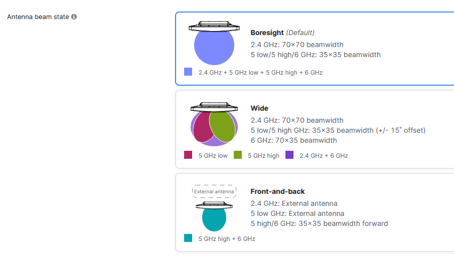
Three selectable beam patterns are available.
- Wide
- Narrow (Boresight)
- Front-and-back
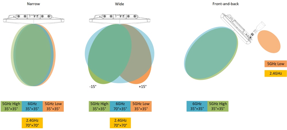
| Slot 0 (2.4GHz) |
Slot 1 (5GHz) |
Slot 2 (5GHz) |
Slot 3 (6GHz) |
|
| Wide |
70° × 70° |
35° × 35° |
35° × 35° |
70° × 35° |
| Narrow (Boresight) |
70° × 70° |
35° × 35° |
35° × 35° |
35° × 35° |
| Front-and-back |
- |
35° × 35° |
- |
35° × 35° |
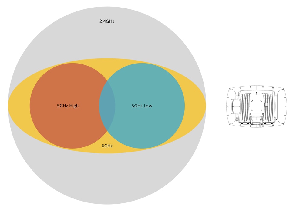
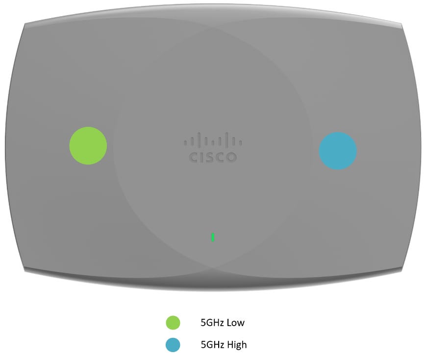
In wide mode the 5GHz beams are steered by 15° (each) away from each other.
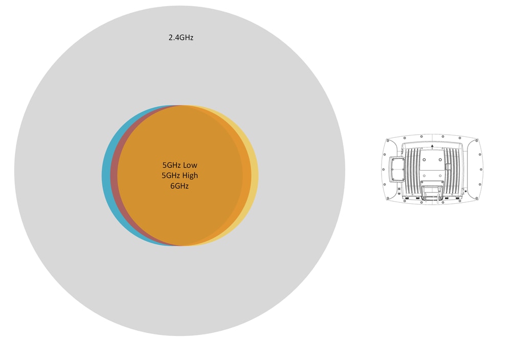
The diagrams are for illustrative purposes and not to scale.
Wide - Top View
Narrow (Boresight) - Top View
Front-and-back - Top View
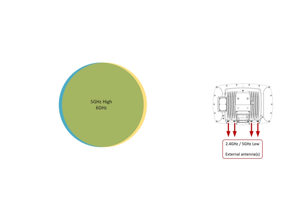
Note: In front-and-back mode 2.4GHz and 5GHz Low are redirected to the N-Type connectors, external antenna(s) are required in this mode.
5GHz High and Low (Band locking)
Each of the two 5GHz radio slots are locked to specific U-NII bands and statically assigned to the radio slots (this is not configurable). The implication of this is that orientation of the 9179F can be significant in some cases, most notably when using the wide setting as the 5GHz beams are separated and not covering the same area. If the RF design calls for a specific area to be covered by a specific channel, then orientation must be considered during installation.
Slot 1 is designated as 5GHz High, Slot 2 is designated as 5GHz Low. Slot 1 switches to full band operation when Dual Radio mode is disabled.
Band allocation with Dual Radio mode enabled.
| Slot 1 (5GHz High) |
Slot 2 (5GHz Low) |
|
| -B domain (FCC) |
U-NII 2e / U-NII 3 |
U-NII 1 / U-NII 2 |
| -E domain (ETSI) |
U-NII 2e |
U-NII 1 / U-NII 2 |
Band allocation with Dual Radio mode disabled.
| Slot 1 (5GHz Full) |
|
| -B domain (FCC) |
U-NII 1 / U-NII 2 / U-NII 2e / U-NII 3 |
| -E domain (ETSI) |
U-NII 1 / U-NII 2 / U-NII 2e |
U-NII bands are referenced throughout this document. Regulatory domains outside of the US can use their own nomenclature for the respective bands.
Antenna Gain
| Slot 0 |
Slot 1 |
Slot 2 |
Slot 3 |
|
| 2.4GHz |
5GHz High |
5GHz Low |
6GHz |
|
| Wide |
6 |
12 |
12 |
7 |
| Narrow (Boresight) |
6 |
12 |
12 |
12 |
| Front-and-back |
6** |
12 |
6** |
12 |
**Front-and-back mode disables the onboard antennas for the 2.4GHz and 5GHz Low slots and redirects the signal output to the rear N-type connectors.
Balancing Tx Power
In high-density scenarios it is important to keep the Tx power balanced between the radios, this is to avoid the stronger radio from attracting more client devices and leading to uneven load distribution between the radios. In extreme cases, there is a risk all client devices in the coverage area connecting only to one of the radios. This applies mostly to the two 5GHz radios but can also apply to the 6GHz radio when designing for MLO (Multi-Link Operation).
Example: In the ETSI (-E) regulatory domain the maximum usable EIRP is 23dBm in U-NII 1 & U-NII 2. When using the narrow (boresight) setting with 12dBi gain the maximum usable transmit power is 11dBm for Slot 2. In this scenario, it is good practice to set the maximum Tx power for the remaining radio (Slot 1) to match 11dBm as closely as possible.
Power balance can also need to be considered when planning for MLO across 5GHz and 6GHz bands, although there is some additional complexity. Firstly, antenna gain for the 6GHz slot changes with configuration (7dBi in wide mode, 12dBi in narrow mode), meaning that EIRP values must be considered. Secondly, EIRP for 6GHz changes with channel width. These differences between 5GHz and 6GHz can make it more challenging to find a balanced power configuration for both bands. While early 6GHz testing suggests that clients prefer (or stick to) the wider channel of the 6GHz band regardless of the EIRP difference, finding a good balance between 5GHz and 6GHz can become significantit as client roaming algorithms mature over time.
Distance
Please see Design Guide CX - Wireless for Large Public Networks for more information about designing large high-density networks.
The antenna has been tested for basic client connectivity at distances of up to 60m (~200ft) in narrow (boresight) beam configuration at maximum power. However, mounting any antenna closer to the client device always results in better performance.
While the 9179F is capable of connecting client devices at long distances – large high-density deployments from long distances must be avoided if possible. As distance increases it is critical to consider the size of the resulting coverage area.
Coverage area of the antenna grows exponentially with the distance; at higher distances the resulting coverage area can be too large for the intended use-case, it is important that all high-density 9179F deployments are validated by an experienced wireless professional.
These calculations show an example of a coverage area calculated at 60m (~200ft).
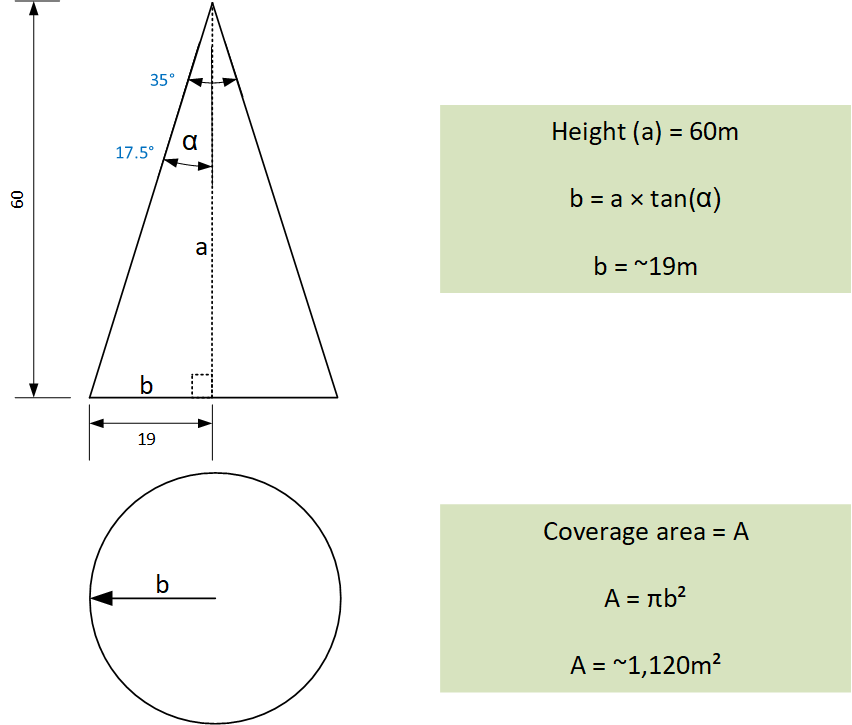
The resulting coverage area at 60m (~200ft) is over 1120m² (~12,100 sq ft), in a high-density environment this area represents a potentially excessive number of users, significantly larger than a good target number of users per radio. Simply put, at this height the antenna can ‘see’ more users than it can reliably serve at high speed. In general, the larger the distance from the antenna to the client, the lower the client density of the target area must be. This is an important consideration for very high-density areas such as concerts and stadiums, in these very high-density scenarios a typical mounting distance would be around 30m (~100ft).
Estimated coverage area at various heights (narrow mode):
| 20m (~65 ft.) |
125m² (1,345 sq ft.) |
| 30m (~100 ft.) |
281m² (3,026 sq ft.) |
| 40m (~130 ft.) |
500m² (5,379 sq ft.) |
| 50m (~165 ft.) |
781m² (8,404 sq ft.) |
| 60m (~200 ft.) |
1,124m² (12,102 sq ft.) |
Note: These calculations are purely academic and only intended to highlight the order of magnitude. In practice, the radio cell is even larger as the antenna’s coverage does not stop at the listed -3dB beamwidth.
For low-density deployments with lower data rate requirements (for example, outdoor IoT), the 9179F can be used at distances of over 60m (~200ft), in this case the mandatory data rate would need to be adjusted downwards.
Radio Resource Management (RRM)
RRM and AI-RRM are enabled in software for the CW9179F to guide the installer. The hyper-directional nature of the CW9179F provides precision coverage, and in dense deployments must be designed correctly to avoid inconsistencies. Design best practices for stadiums and large public networks advise setting specific TPC Min/Max power to set design power goals. Channel selection can be made dynamically, then verified by a professional. Always validate the outcomes using professional wireless survey tools.
5GHz TDWR channels (120, 124, 128) are supported.
Flexible Radio Assignment (FRA) and Radio Roles
Static configuration of radio roles (for example Client Serving) is recommended, the use of Flexible Radio Assignment (FRA) is not recommended.
Orientation
The 9179F can be installed in landscape (horizontal) or portrait (vertical) orientation.
Weight
The 9179F unit has a weight of 4.54kg (10lbs.), the articulating mount is an additional 1.72kg (3.8lbs.), that is 6.26kg (13.8lbs) for both.
Accelerometer
The 9179F is equipped with an accelerometer making it easier to verify installed antenna angles. The accelerometer can be enabled in the Catalyst 9800 graphical interface or in the command line using the command:
ap name <name> no sensor environment accelerometer shutdownTilt angle for the antenna can be verified in the Catalyst 9800 graphical interface or in the command line using the command:
show platform software process database wncd chassis active R0 details WNCD_DB "table tbl_ap_accelerometer" contentAlternatively, accelerometer values can be queried using NETCONF by using the XPATH:
/access-point-oper-data/ap-accelmtrPower Requirements
802.3bt power is required for full (4x4) operation on all radios, for both indoor and outdoor modes.
It is possible to operate the unit at reduced functionality (2x2 on all radios) using 802.3at power.
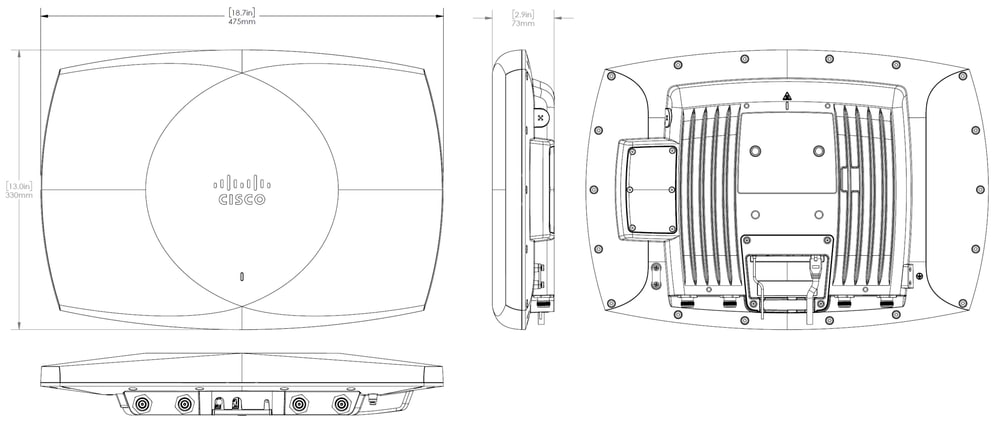
Dimensions
Front-and-back mode
Front-and-back mode is designed specifically for stadium/arena use-cases where the primary coverage is provided by the main beam of the antenna, and secondary (rear-facing) coverage is also required. In this mode the 9179F redirects signal output for Slot 0 (2.4GHz) and Slot 2 (5GHz Low) to its N-Type connectors, allowing for an external antenna to be attached.
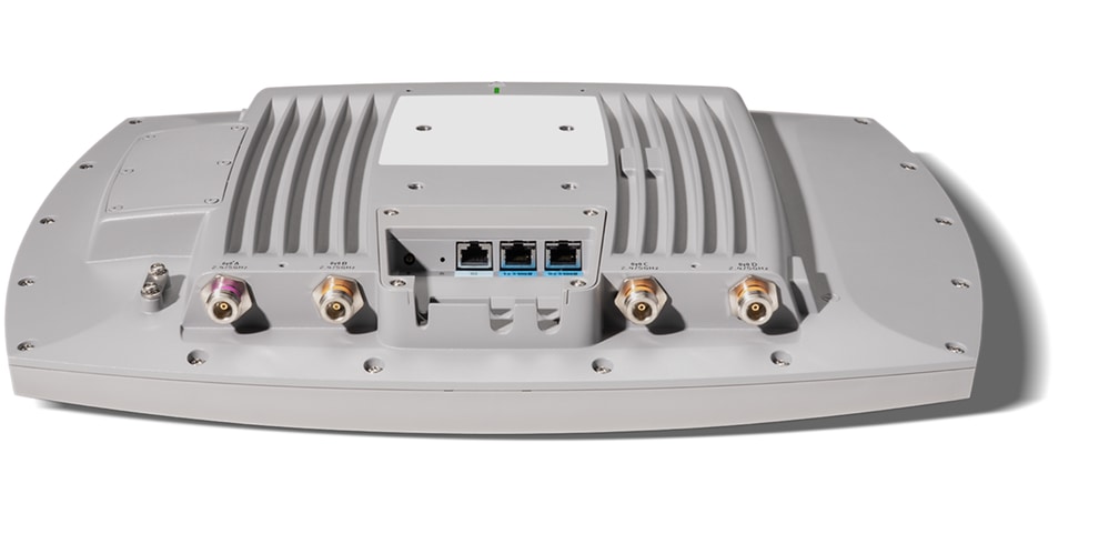
Any supported SIA antenna can be attached to the four N-Type connectors at the rear of the 9179F, note that only the left-most port is SIA capable. A dedicated 6dBi mini-patch antenna is available specifically for this purpose. The CW-ANT-T-D3-N is a dual-band 2.4GHz and 5GHz antenna with a 90°×60° (Azimuth × Elevation) beamwidth in 5GHz and 125°×60° (Azimuth × Elevation) beamwidth in 2.4GHz.
Higher gain (>6dBi) and non-SIA antennas are not supported at the time of writing this guide.
Outdoor 6GHz
Outdoor 6GHz operation (Standard Power) is enabled by installing the additional outdoor environment pack (CW-ACC-9179-B-00), sold separately. This enables 6GHz operation using AFC in countries that allow it. Note that the outdoor environment pack in not hot-swappable.
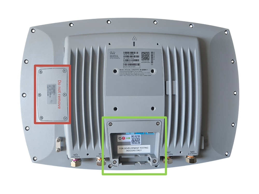
View in indoor mode:
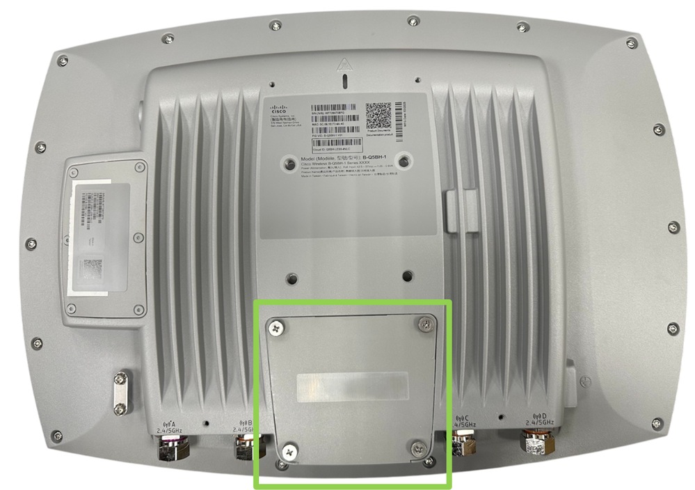
View in outdoor mode:
The current environment mode can be verified using the command:
show ap name <name> config general | include EnvironmentQuick Connect
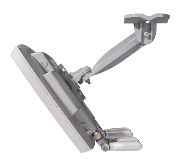
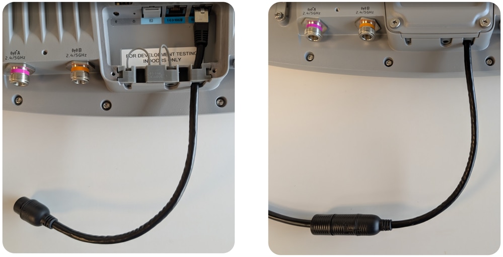
When deploying the 9179F outdoors and at height, it is safer and easier to install the outdoor environment pack at ground level before lifting the 9179F up to its final mounting position. The additional quick connect cable simplifies the installation of the 9179F at height by extending the ethernet connection outside of the weatherized outdoor environment pack.
The quick connect cable is purchased separately, part number CW-ACC-QCKCNCT1.
Site Survey
To switch the AP into site survey mode, enter this command in the AP CLI:
ap-type site-surveyThe local site survey graphical interface is available after the AP reboots. Default credentials are admin/admin. Switching back to CAPWAP mode is possible via Console using credentials cisco/Cisco and this command :
ap-type capwap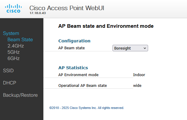
Config drift
When using traditional antennas, changing the coverage area typically requires that the antenna be physically moved or adjusted. As the 9179F is software controlled it is possible to change the coverage area using only configuration. This puts emphasis on good configuration practices such as regular configuration back-ups and avoidance of configuration drift. Loss of configuration or unintended changes to RF tags and/or RF profiles can result in significant changes to the coverage area.
Configuration
Catalyst
From Cisco IOS XE version 17.18 there is an additional configuration option in the RF Tag section. Note that the beam pattern configuration mode differs from the configuration method of the C-ANT9104.
Navigate to: Configuration > Tags > RF
AP Beam State can be selected from one of the options: Boresight | Wide | Front-and-back

Meraki
Antenna beam state configuration is available in RF Profile settings
Navigate to: Wireless > Radio Settings > RF Profiles, then select the appropriate RF profile. Antenna beam configuration can be selected as per this image.
Revision History
| Revision | Publish Date | Comments |
|---|---|---|
2.0 |
22-Jan-2026
|
Fixed typos |
1.0 |
23-Sep-2025
|
Initial Release |
 Feedback