Introduction
This document describes the configuration of Fluidity parameters on IW9165 and IW9167 radios in URWB mode.
Prerequisites
Requirements
Cisco recommends that you have knowledge of these topics:
- Basic CLI navigation and commands
- Understanding of IW URWB mode radios
Components Used
The information in this document is based on these software and hardware versions:
The information in this document was created from the devices in a specific lab environment. All of the devices used in this document started with a cleared (default) configuration. If your network is live, ensure that you understand the potential impact of any command.
Background Information
On the IW9165 and IW9167 radios in URWB mode, there are several parameters associated with a Fluidity setup. Fluidity networks are ones where there are Infrastructure radios which are stationary alongside Vehicle radios that are mobile.
The vehicle radios communicate with one Infrastructure radio at a time, which has the best signal strength.
These parameters can be configured over IoT OD with the Industrial Wireless service and over CLI as well.
CLI configuration of Fluidity parameters
Show commands:
These parameters can be executed from enable mode on the CLI of the devices.
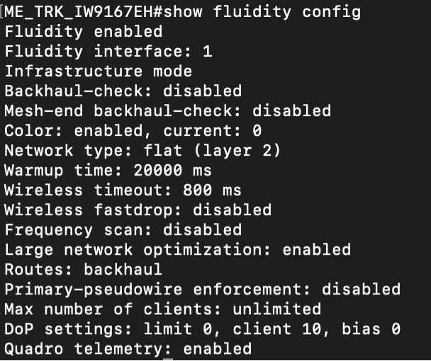
- Current configuration:
The current configuration of the Fluidity parameters on the device can be viewed with this command.
Radio1#show fluidity configuration
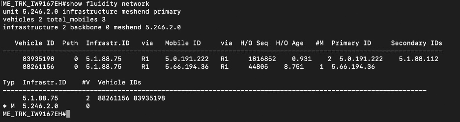
2. Current Fluidity network setup:
This command shows the current setup of the Fluidity network this device belongs to, including all the pseudowires formed and the overall network details.
Radio1#show fluidity network
Configuration commands:
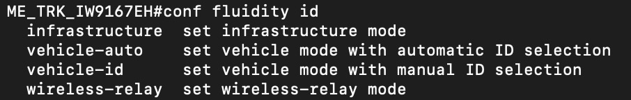
3. Fluidity ID:
This parameter allows to set the role for the device. The ID for the device can be set to Infrastructure mode for static devices, Vehicle for mobile devices and Wireless relay for backhaul devices.
Under Vehicle configuration either an automatic ID can be assigned to all devices that belong to a single vehicle, or this can be manually configured as well.
Radio1#conf fluidity id infrastructure

Radio1# conf fluidity id wireless-relay

Radio1#conf fluidity id vehicle-auto

Radio1#conf fluidity id vehicle-id

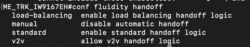
4. Fluidity handoff logic:
This parameter allows to specify the logic to be used when vehicle radio moves between one infrastructure to another.
The default value is standard logic, based on the best RSSI value.
Load-balancing allows to share the load between several infrastructure radios. Manual method disables any automatic handoffs and v2v method is used when Vehicle to vehicle communication is needed.
Radio1#conf fluidity handoff standard

Radio1#conf fluidity handoff manual

Radio1#conf fluidity handoff load-balancing

Radio1#conf fluidity handoff v2v
5. Fluidity connect:
This parameter allows to force a manual connection from the vehicle radio to the infrastructure unit who’s mesh ID is provided. For example this command forces a connection to the Infrastructure unit with Mesh ID 5.1.2.3.
Radio1#conf fluidity connect 5.1.2.3

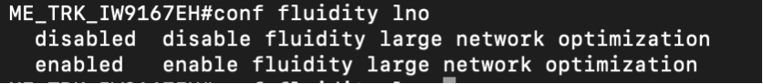
6. Large Network Optimization:
This parameter allows to enable or disable LNO on the device.
Radio1#conf fluidity lno disabled

Radio1#conf fluidity lno enabled
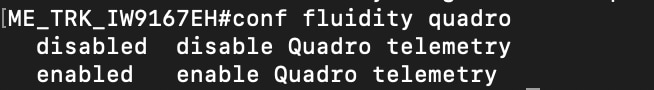
7. Quadro telemetry:
This parameter allows to enable or disable Fluidity Quadro telemetry data.
Radio1#conf fluidity quadro disabled

Radio1#conf fluidity quadro enabled
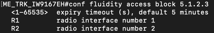
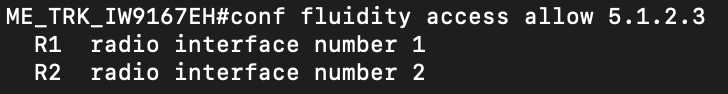
8. Fluidity access:
This parameter helps with either allowing or blocking access to a certain device for a specified amount of time, on the specified radio interface.
Radio1#conf fluidity access allow <mesh ID> <intf>

Radio1#conf fluidity access block <mesh ID> <time in minutes> <intf>
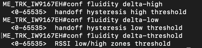
9. Delta values :
This parameter allows to define the delta-high, delta-low and delta-threshold values of the signal strength parameter to be used for the handoff logic which determines handoff between infrastructure radios.
Delta-high refers to the optimum upper handoff hysteresis threshold, Delta-low refers to the optimum lower handoff hysteresis threshold and delta-threshold refers to the Fluidity handoff hysteresis low/high threshold.
Radio1#conf fluidity delta-high <int>
Radio1#conf fluidity delta-low <int>
Radio1#conf fluidity delta-threshold <int>
10. Maximum clients :
This parameter defines the maximum number of vehicle radios each infrastructure radio can connect to. If set to 0, it allows the infrastructure radio to connect to unlimited number of vehicle radios.
Radio1#conf fluidity max-clients 5

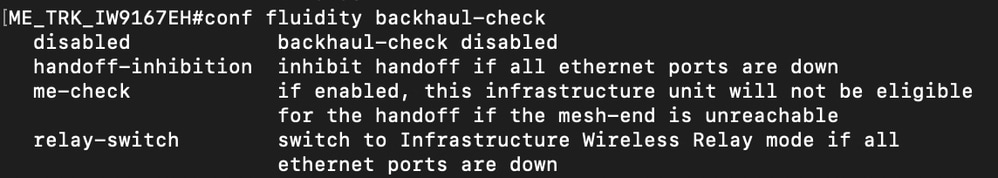
11. Backhaul check:
This parameter allows to define the backhaul check feature on the radios.
If set to disabled, then the backhaul check is not performed.
Radio1#conf fluidity backhaul-check disabled
If set to handoff-inhibition, on an infrastructure device, the device is not considered as an option to handoff, if all the ethernet ports on it are down.
Radio1#conf fluidity backhaul-check handoff-inhibition
If set to relay-switch, the infrastructure device is temporarily switched to wireless relay if the ethernet port is down.
Radio1#conf fluidity backhaul-check relay-switch
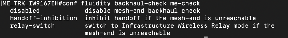
12. Backhaul check meshend check:
This parameter allows to enable a secondary check on the exisitng backhaul check feature. While backhaul check feature only checks for the Ethernet port status, ME-check verifies if the infrastructure unit can actually reach the Mesh End of the network. If the me-check parameter is selected under backhaul check, further options can be specified.
If set to disabled, then me-check is not performed.
Radio1#conf fluidity backhaul-check me-check disabled
If set to handoff-inhibition on an infrastructure device, the device is not considered as an option to handoff if it cannot reach the Mesh End of the network.
Radio1#conf fluidity backhaul-check me-check handoff-inhibition
If set to relay-switch, the infrastructure device temporarily switches to wireless relay if the Mesh End is not reachable.
Radio1#conf fluidity backhaul-check me-check relay-switch
13. Degree of Preference (DoP):
This parameter allows to define the Degree of Preference value. The Degree of Preference (DoP) is a crucial adimensional metric in Fluidity network, used to assess the load level of each network units, whether mobile or infrastructure. DoP enables smart network management by using real-time load information to guide connection decisions.
For detailed info on the Degree of Preference parameter, please refer to this article:
Configure Load Balancing on APs in CURWB Mode
To define the dop bias :
Radio1#conf fluidity dop bias <int>
To define the dop limit :
Radio1#conf fluidity dop limit <int>
To define the dop per-cleint overhead :
Radio1#conf fluidity dop client <int>

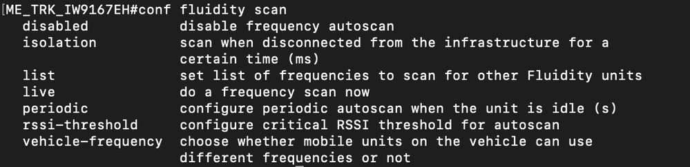
14. Fluidity scan :
This parameter allows to define the Frequency autoscan feature options.
To disable frequency autoscan:
Radio1#conf fluidity scan disabled
To initiate a frequency scan after the vehicle device is disconnected from infrastructure for a certain time.
Radio1#conf fluidity scan isolation <time in ms>
To define a list of frequencies to scan for other infrastructure units or to clear the list.
Radio1#conf fluidity scan list <list of channels>

Radio1#conf fluidity scan list clear
To initiate a live frequency scan
Radio1#conf fluidity scan live
To initiate a periodic frequency scan when the unit is idle and to disable it
Radio1#conf fluidity scan periodic <time in seconds>

Radio1#conf fluidity scan periodic disabled
To define the RSSI threshold to trigger a frequency autoscan and to disable it
Radio1#conf fluidity scan rssi-threshold <value in db>

Radio1#conf fluidity scan rssi-threshold disabled
To define if all units on the same vehicle are to use the same frequency or allowed to use different frequencies.
Radio1#conf fluidity scan vehicle-frequency locked

Radio1#conf fluidity scan vehicle-frequency open
For further details on the frequency autoscan feature refer to this article :
Configure Multi Frequency with Fluidity on APs in CURWB Mode
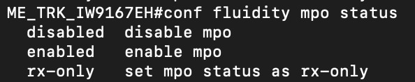
15. MPO:
This parameter allows to define values for the Multi Path Operation feature.
To enable or disable MPO :
Radio1#conf fluidity mpo status enabled
Radio1#conf fluidity mpo status disabled
To enable MPO only on received traffic :
Radio1#conf fluidity mpo status rx-only
To confugure the CoS of the traffic for MPO :
Radio1#conf fluidity mpo cos <cos value 0 to 7>

To configure the maximum number of MPO paths allowed:
Radio1#conf fluidity mpo path max <1-4>

To configure the minimum RSSI value to trigger MPO :
Radio1#conf fluidity mpo rssi min <rssi value>

To enable or disable sending MPO Telemetry data :
Radio1#conf fluidity mpo telemetry enabled

Radio1#conf fluidity mpo telemetry disabled

16. Enforce Psuedowire Principal access :
This feature is used to either enable or disable access to onboard client devices from the Primary vehilce device.
Radio1#conf fluidity enforce-pws-primary enabled
Radio1#conf fluidity enforce-pws-primary disabled

17. Wireless Fastdrop:
This parameter allows to configure the maximum number of consecutive packets that can be lost, before wireless fastdrop is trigerred.
This allows the infrastructure devices to drop Vehicle radios once the configured number of consecutive packets are lost.
Radio1#conf fluidity fastdrop count <packet count>

18. Routes :
This parameter allows to define if only backhaul routes are to be advertised or both backhaul and vehilce routes are to be advertised.
This parameter needs to be set to all if Vehicle to Vehilce communication is needed.
Radio1#conf fluidity routes backhaul

Radio1#conf fluidity routes all

19. Timeout :
This parameter allows to defining the timeout value in ms within which if the Vehicle radio does not receive a signalling packet from an Infrastructure radio; it clears out the all the information associated with that Infrastructure unit.
Radio1#conf fluidity timeout <value in ms>

20. VLAN :
This parameter allows to add, show or clear VLAN data used in Layer 3 networks .
To add a VLAN :
Radio1#conf fluidity vlan <subnet> <netmask> <vlan id>
To clear VLANs :
Radio1#conf fluidity vlan clear
To show VLANs :
Radio1#conf fluidity vlan show

21. Warmup time :
This parameter allows to define the warmup time in ms on the device. If the device is in Infrastructure mode it does not accept any connections during this time. If the device is in Vehicle mode it does not initiate any connections during this time.
The warmup time counter is trigerred during this sequence:
1. Whenever the device is rebooted/activated.
2. If the LAN port on the device is activated/deactivated.
3. When the device does the first RADIUS authentication.
4. When backhaul check is trigerred.
Radio1#conf fluidity warmup <time in ms>

 Feedback