Introduction
This document describes the configuration of a Fluidity layer 2 setup for CURWB devices and provides guidance on troubleshooting the network.
Components Used
The configuration involves four different hardware components:
- Cisco Catalyst IW9167
- Cisco Catalyst IW9165E
- FM4200F
- FM3500
The information in this document was created from the devices in a specific lab environment. All devices used in this document started with a cleared (default) configuration. If your network is live, ensure that you understand the potential impact of any command.
What is Fluidity?
In CURWB Fluidity is a network architecture based on utilizing Multiprotocol Label Switching (MPLS) technology to deliver IP-encapsulated data.
In a Cisco Ultra-Reliable Wireless Backhaul mobility network scenario, the handoff process resembles a network topology change where an existing link is broken, and a new link is established.
However, conventional industry mechanisms for detecting changes and reconfiguring nodes are often too slow and data-intensive to maintain optimal performance in real-time scenarios, such as high-speed mobility.
To address these challenges, Fluidity implements a fast handoff solution that provides rapid path reconfiguration with latency as low as one millisecond.
This active mechanism extends the existing control plane of the network, leveraging a specific manipulation technique for the node MPLS FIB tables.
In the Fluidity scheme, mobile nodes establish pseudo wires with trackside radios upon mutual detection. As the vehicle moves along the track, it initiates handoff from one trackside to another based on various fluidity parameters.
This ensures onboard client devices maintain their IP addresses throughout the mobility process, and all nodes are integrated into a single layer-2 mesh network.
Configuring Fluidity:
Topology: One IW9167 APs and one FM3500 radio acting as trackside or wayside radio. These two are providing coverage for the vehicles. They are connected to the core network via ethernet cables. At the same time, we have three vehicles. One FM4200F, one FM3500 and finally one IW9165E acting as vehicle.
Configuring Layer2 Fluidity via GUI:
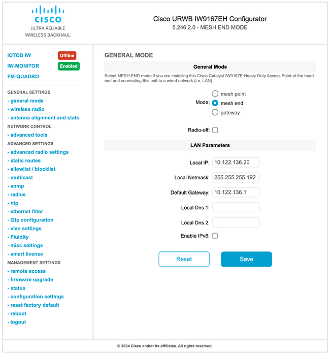
- GENERAL SETTINGS > General Mode: IW9167 is acting as the ingress/egress point for the CURWB network, which is why IW9167 needs to be configured as mesh end. The rest of the radios including the vehicles must be in mesh point mode.
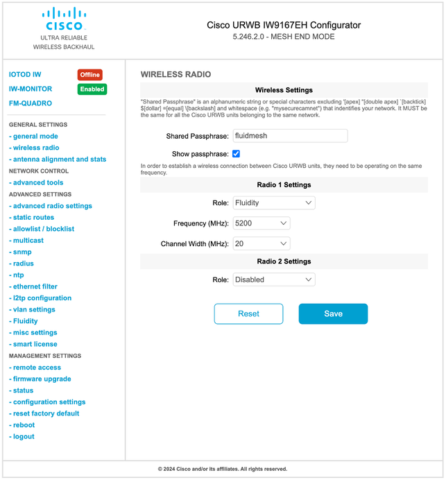
- GENERAL SETTINGS > Wireless Radio: All track side and vehicle radios need to share the same shared passphrase, frequency, and channel width.
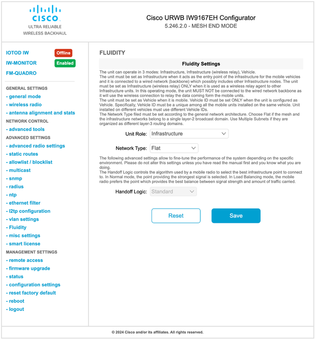
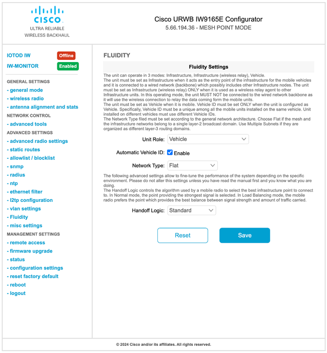
- Advanced Settings > Fluidity: The trackside radios which provide coverage for the vehicles, need to be configured as Infrastructure. On the other side, the vehicle radios need to be configured as a vehicle.
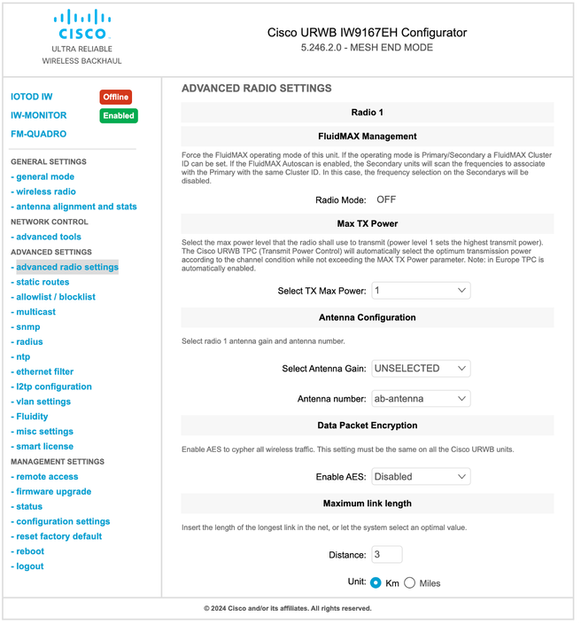
- Advanced Settings > Advanced Radio Settings: When using 2x2 MIMO, select ab-antenna as the antenna number.
- For the IW9167, if using 2x2 MIMO with interface 1, connect to antenna ports 3 and 4. If configured for interface 2, use antenna ports 5 and 6.
- For the IW9165D, interface 1 has a built-in antenna. If connecting an external antenna, use interface 2.
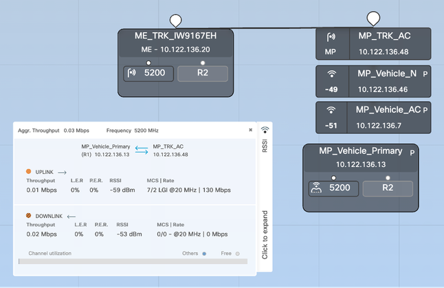
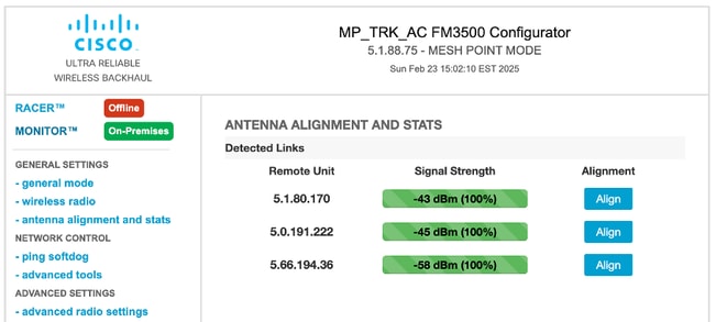
- Finalizing Configuration: After configuring all settings, save the configuration and apply the changes. Once the Access Points (APs) reboot and the radios are back online, you can check the RSSI from the Antenna Alignment page and monitor live connectivity from the FM-Quadro page.
Configuring Layer2 Fluidity via CLI:
Trackside Configuration:
ME_TRK_IW9167EH#configure modeconfig mode meshend
Note: Tracksides other than mesh end needs to be configured as “meshpoint”

ME_TRK_IW9167EH#configure ap address ipv4 static IP NETMASK GATEWAY DNS1 DNS2
ME_TRK_IW9167EH#configure dot11Radio 1 frequency 5180
ME_TRK_IW9167EH#configure dot11Radio 1 bandwidth 20
ME_TRK_IW9167EH#configure wireless passphrase URWB
ME_TRK_IW9167EH#configure dot11Radio 1 mode fluidity
ME_TRK_IW9167EH#configure fluidity id infrastructure
ME_TRK_IW9167EH#write
ME_TRK_IW9167EH#reload
Vehicle configuration:
MP_V_IW9165E#configure modeconfig mode meshpoint
MP_V _IW9165E#configure ap address ipv4 static IP NETMASK GATEWAY DNS1 DNS2
MP_V _IW9165E#configure dot11Radio 1 frequency 5180
MP_V _IW9165E#configure dot11Radio 1 bandwidth 20
MP_V _IW9165E#configure wireless passphrase URWB
MP_V _IW9165E#configure dot11Radio 1 mode fluidity
MP_V _IW9165E#configure fluidity id vehicle-auto
MP_V _IW9165E#write
MP_V _IW9165E#reload
Troubleshooting Fluidity:
In mobility/fluidity applications, various issues possibly arise, such as lower than expected throughput, intermittent connectivity, latency challenges, and interference.
Physical Issues with Signal Strength:
- Ensure the use of CURWB-supported antennas, correctly connected to radios within recommended guidelines, and oriented in the proper direction.
- Confirm that overlapping coverage is adequate throughout the track.
- Maintain a direct line of sight for radios.
High Channel Utilization:
- Mitigate interference through strategic RF planning.
- Utilize multiple frequency deployments with frequency scanning for seamless handover, requiring two radios per vehicle.
- Ensure radios are positioned at least 10 feet apart at the same height, and maintain a minimum of 3 feet between radios on the same pole to prevent interference from nearby devices.
Throughput Issues:
Throughput problems can result from several factors:
- Strong signal strength is vital for optimal throughput; weaker signals reduce modulation rates and throughput. Aim for a signal strength between -45 dBm and -70 dBm.
- High channel utilization can also lead to throughput degradation.
Latency Issues:
Latency issues, particularly in sensitive applications, possibly stem from:
- Inadequate signal strength along the track.
- Interference affecting frequency performance.
- The need for Quality of Service (QoS) configurations on radios and switches.
- Fluidity settings requiring verification and fine-tuning according to PLC configurations.
Tools for Troubleshooting:
IW-Monitor is a valuable tool for monitoring fluidity network performance. In the event of a failure, leverage historical data on RSSI, jitter, latency, LER, and PER to diagnose the root cause.
 Feedback