Introduction
This document describes the configuration of LNO parameter on IW9165 and IW9167 radios in URWB mode.
Prerequisites
Requirements
Cisco recommends that you have knowledge of these topics:
- Basic CLI navigation and commands
- Understanding of IW URWB mode radios
Components Used
The information in this document is based on these software and hardware versions:
- IW9165 and IW9167 radios
- Industrial Wireless service
The information in this document was created from the devices in a specific lab environment. All of the devices used in this document started with a cleared (default) configuration. If your network is live, ensure that you understand the potential impact of any command.
Background Information
Large Network Optimization (LNO) is a feature used in both Layer 2 and Layer 3 extensive networks where there are 50 or more infrastructure radios involved. URWB radios communicate with each other by building pseudowires or Label Switched Paths (LSPs) between themselves as they send data over MPLS protocol. When networks get to a size of 50 or more infrastructure radios, the overhead resulting in setting up pseudowires between all the radios becomes significant and can affect network performance. Hence, the LNO parameter needs to be enabled in these cases.
LNO, when enabled, forces all the infrastructure radios to build pseudowires only to the Mesh End of the Infrastructure setup and disables BPDU forwarding as well. If LNO is disabled, the infrastructure radios build pseudowires to the Mesh End and between each other and this enables BPDU forwarding.
Configure
The LNO feature cannot be configured on the GUI of the radios. Configuring this parameter needs CLI access to the Infrastructure radios, with privilege mode access.
To enable LNO :
#configure fluidity lno enabled
To disable LNO :
#configure fluidity lno disabled

The MPLS tunnels built between the radios can be verified from the CLI output of this command :
#show mpls config
Network Diagram
In order to understand LNO, we are looking at a simple example configuration here with 3 Infrastructure radios (1 Mesh End and 2 Mesh Points) and 1 Vehicle radio.
With LNO disabled :
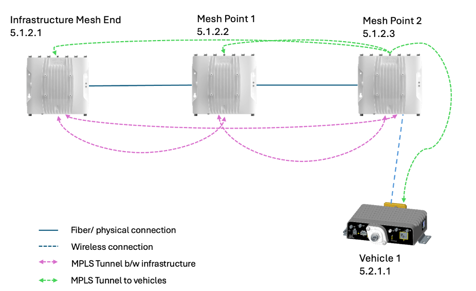
While LNO is disabled, check the #show mpls config output and you can see the pseudowires being built from all the Infrastructure radios to other Mesh points and the Mesh End. The psuedowires to vehicles are also built and not affected by LNO parameter.
For example, here :
Mesh Point 2, builds tunnels to Mesh Point 1 and Infrastructure Mesh End.
Mesh Point 1, builds tunnels to Mesh Point 2 and Infrastructure Mesh End.
Infrastructure Mesh End builds tunnels to Mesh point 1 and Mesh point 2.
With LNO enabled :
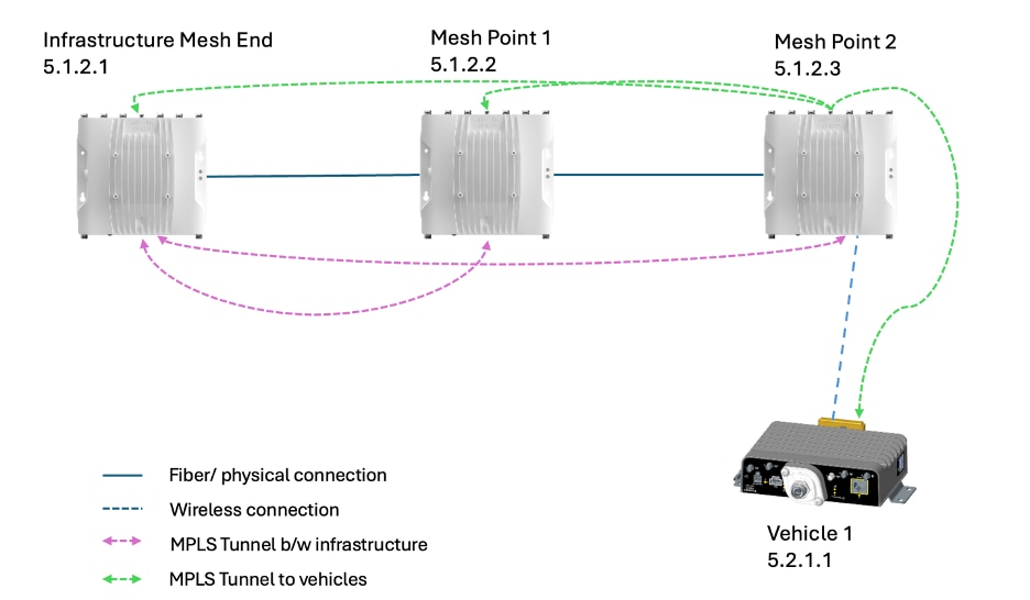
While LNO is enabled, check the #show mpls config output and you can see the pseudowires being built from all the Infrastructure Mesh points to only the Mesh End. The psuedowires to vehicles are also built and not affected by LNO parameter.
For example, here :
Mesh Point 2, builds tunnels to Infrastructure Mesh End.
Mesh Point 1, builds tunnels to Infrastructure Mesh End.
Infrastructure Mesh End builds tunnels to Mesh point 1 and Mesh point 2.
Verifying pseudowires from CLI output
MPLS tunnels built can be verified from CLI with the command #show mpls config
With LNO disabled :
Example show mpls config output from Mesh point 1:
***** LDP Status ***************************

lsps 3

<5.1.2.2 5.1.2.1 1597753317> ESTABLISHED ftn 1 ilm 410000 pi- 12.116292585 ka 0 { 5.1.2.2 5.1.2.1}

<5.1.2.2 5.1.2.3 513847710> ESTABLISHED ftn 3 ilm 410001 pi- 26.201298102 ka 0 { 5.1.2.2 5.1.2.3 }

<5.1.2.2 5.2.1.1 756184397> ESTABLISHED ftn 4 ilm 410002 pi- 26.201318894 ka 0 { 5.1.2.2 5.1.2.3 5.2.1.1 }
The output indicates the number of pusedowires built from lsps 3 and each line indicates the beginning radio's mesh id and the end radio's mesh id.
ftn indicates the forwarding table entry's index.
ilm indicates the incoming label mapping entry index.
pim cell contains the flag indicating the status of the pseudowire.
- indicates infrastrucuture
m indicates mobile radio (vehicle radio)
Cells within { } indicate the tunnel path from beginning radio to end radio.
With LNO enabled :
***** LDP Status ***************************

lsps 2

<5.1.2.2 5.1.2.1 1597753317> ESTABLISHED ftn 1 ilm 410000 pi- 12.116292585 ka 0 { 5.1.2.2 5.1.2.1 }

<5.1.2.2 5.2.1.1 513847710> ESTABLISHED ftn 3 ilm 410001 pim 26.201298102 ka 0 { 5.1.2.2 5.1.2.3 5.2.1.1 }
The output indicates the number of pusedowires built from 'lsps 2' and each line indicates the beginning radio's mesh id and the end radio's mesh id.
ftn indicates the forwarding table entry's index.
ilm indicates the incoming label mapping entry index.
pim cell contains the flag indicating the status of the pseudowire.
- indicates infrastrucuture
m indicates mobile radio (vehicle radio)
Cells within { } indicate the tunnel path from beginning radio to end radio.
Related Information
```
 Feedback