Introduction
This document describes the T1/E1 interface clocking mechanism and multi-clock synchronization configuration for Cisco C8300 routers.
Prerequisites
Requirements
Cisco recommends that you have knowledge of these topics:
Primary Rate Interface (PRI)
Integrated Services Digital Network (ISDN)
Private Branch Exchange (PBX)
Components Used
This document applies to voice routers with two Network Interface Module (NIM) cards, including:
- Cisco Catalyst 8300 Series Edge Platforms
- Cisco 4000 Family Integrated Services Routers
The information in this document was created from the devices in a specific lab environment. All of the devices used in this document started with a cleared (default) configuration. If your network is live, ensure that you understand the potential impact of any command.
Background Information
Cisco C8300 routers have a different architecture compared to previous router generations. To use clocking from multiple sources, each source requires a Network Interface Module. On a single NIM, all T1/E1 lines with voice ports must use the same clock source on the remote side. If your router has more than one NIM module, you can configure multiple clock sources.

Note: You can configure one clock source per NIM module, meaning the number of clock sources matches the number of NIM modules in the router.
When you integrate the C8300 platform with a PRI configuration, review the specifications of each model:
|
Model
|
Description
|
|
C8300-2N2S-4T2X
|
2 SM and 2 NIM slots, and 2 x 10-Gigabit Ethernet and 4 x 1-Gigabit Ethernet ports
|
|
C8300-2N2S-6T
|
2 SM and 2 NIM slots, and 6 x 1-Gigabit Ethernet ports
|
|
C8300-1N1S-4T2X
|
1 SM slot and 1 NIM slot, and 2 x 10-Gigabit Ethernet and 4 x 1-Gigabit Ethernet ports
|
|
C8300-1N1S-6T
|
1 SM slot and 1 NIM slot, and 2 x 10-Gigabit Ethernet and 4 x 1-Gigabit Ethernet ports
|
Based on these specifications, you can configure multi-clocking only on the C8300-2N2S-4T2X and C8300-2N2S-6T models.
Restrictions
This section outlines the restrictions for configuring network clock synchronization on a router.
- You can configure two ports per NIM as clock sources on a router.
- It is recommended that you do not configure multiple input sources with the same priority because this impacts the TSM (switching message delay).
- The quality of a clock source is not considered by the router. Synchronization Status Messages (SSMs), which inform neighboring network elements about the quality level of a clock, are not supported by the router. The router selects the clock source based on availability and configured priority.
Configure
Hardware Architecture Diagram
This section explains the architecture of the T1/E1 interfaces on a C8300-2N2S router.
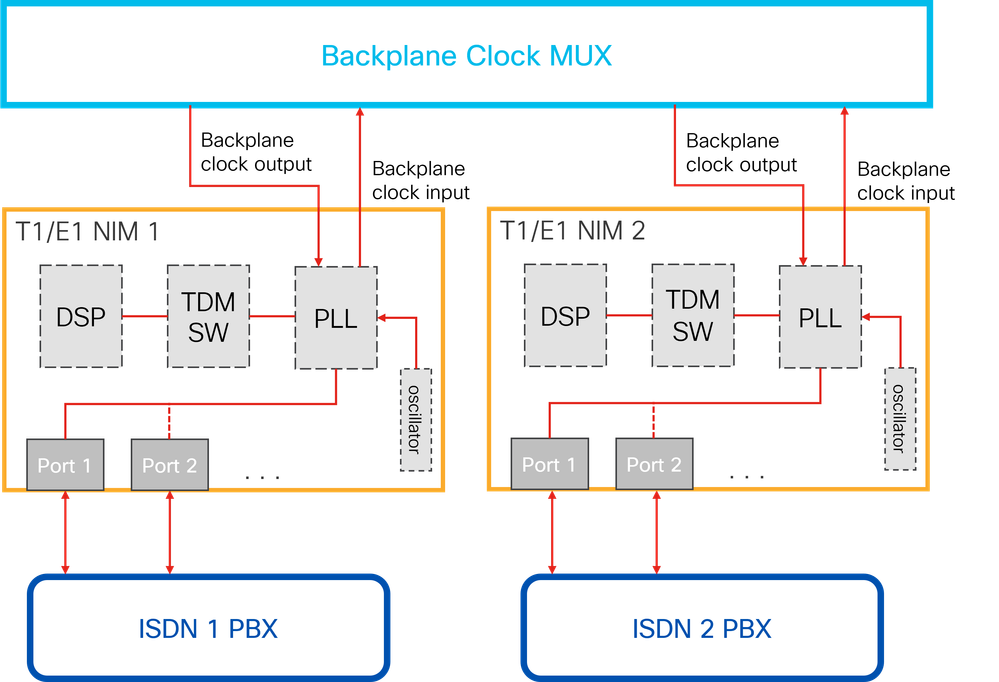 C8300-2N2S Hardware Architecture Diagram
The Backplane Clock Multiplexer (MUX) enables clock synchronization across modules, but synchronizing with the backplane is optional. If you assign each module to a different clock source, the module can connect to different devices providing the respective clock signals.
You must carefully plan clock synchronization and evaluate the feasibility of multi-clocking for your platform model. Incorrect clock synchronization can cause line slips, which can degrade audio quality and disrupt fax transmission.
Configuration
When you configure multi-clocking for T1/E1 controllers, you encounter two possible scenarios:
- Pull clocking from one source on a NIM and inject it into another.
- Synchronize clocking with a different source for each NIM.
General Guidelines for Network-Clock Synchronization
- You must configure the network-clock synchronization automatic global command in both scenarios. This command ensures clocking starts on the modules. Depending on the Cisco IOS® XE version, it is possible that this command is disabled by default.
- If the network-clock synchronization participate command is not configured for a NIM module, that module operates as its own clock domain.
- The network-clock input-source priority controller [t1|e1] slot/bay/port command configures the backplane clock source and sets its priority.
- If your NIM has more than two T1/E1 ports, you can leave the additional ports with the default configuration (clock source line).
- To provide clocking to the line, use the command: clock source network
- The clock source internal command applies only to data T1/E1 and is not used for T1/E1 voice. You can run both data and voice on the same NIM module.
- To recover the clock source from the line, use the command: clock source line [primary | secondary]
Note: When you recover clocking from the line, always select a primary input source. Configuring a secondary input source is optional.
Example 1. Pull Clocking from One Source on a NIM and Inject It into Another
For this scenario, the clocking is pulled from the ISDN 1 PBX to the NIM 1 and at the same time the NIM 2 is using the same clocking by pulling the signal from the backplane clock.
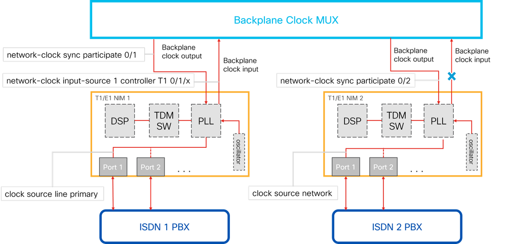 Clock Synchronization from one NIM to Another
Router(config)# network-clock synchronization automatic
Router(config)# network-clock synchronization participate 0/1
Router(config)# network-clock input-source 1 controller T1 0/1/0
Router(config)# network-clock synchronization participate 0/2

Router(config)# controller T1 0/1/x
Router(config-controller)# clock source line primary

Router(config)# controller T1 0/2/x
Router(config-controller)# clock source network
Example 2. Synchronize Clocking with a Different Source for Each NIM.
In this configuration, each NIM uses the line as its clock source and does not synchronize with the backplane. NIM 1 synchronizes with ISDN 1 PBX as its clock source, while NIM 2 synchronizes with ISDN 2 PBX as its clock source.
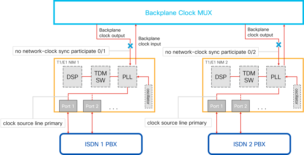 Clock Synchronization of Different Sources for Each NIM
Router(config)# network-clock synchronization automatic
Router(config)# no network-clock synchronization participate 0/1
Router(config)# no network-clock synchronization participate 0/2

Router(config)# controller T1 0/1/0
Router(config-controller)# clock source line primary

Router(config)# controller T1 0/2/0
Router(config-controller)# clock source line primary
Verify
The show controller t1 command provides information about the controller hardware status and is useful for diagnostic tasks, including those performed by technical support. This command also provides:
- Statistics about the T1 link. If you specify a slot and port number, it displays statistics for each 15-minute interval.
- Information to troubleshoot physical layer and data link layer issues.
- Local or remote alarm information, if any, on the T1 line.
To verify clock synchronization within the controllers, monitor the Slip Secs counter. A value of 0 for this counter indicates proper clock synchronization.

Tip: Use the clear counters command to reset the T1 counters. Clearing the counters helps you easily monitor whether the T1/E1 line experiences any slips. Keep in mind that this command also resets all other interfaces counters.
Here is an example of the show isdn status command output. In this example, the Slip Secs counter is 0 for each controller, which confirms that the clocks are synchronized.
C8300#show controller t1
T1 0/1/0 is up
  Applique type is Channelized T1
  Cablelength is long gain36 0db
  No alarms detected.
  alarm-trigger is not set
  Soaking time: 3, Clearance time: 10
  AIS State:Clear  LOS State:Clear  LOF State:Clear
  Framing is ESF, Line Code is B8ZS, Clock Source is Network.
  BER thresholds:  SF = 10e-3  SD = 10e-6
  Data in current interval (14 seconds elapsed):
     0 Line Code Violations, 0 Path Code Violations
     0 Slip Secs, 0 Fr Loss Secs, 0 Line Err Secs, 0 Degraded Mins
     0 Errored Secs, 0 Bursty Err Secs, 0 Severely Err Secs, 0 Unavail Secs
  Total Data (last 24 hours)
     0 Line Code Violations, 0 Path Code Violations,
     0 Slip Secs, 0 Fr Loss Secs, 0 Line Err Secs, 0 Degraded Mins,
     0 Errored Secs, 0 Bursty Err Secs, 0 Severely Err Secs, 0 Unavail Secs
T1 0/1/1 is up
  Applique type is Channelized T1
  Cablelength is long gain36 0db
  No alarms detected.
  alarm-trigger is not set
  Soaking time: 3, Clearance time: 10
  AIS State:Clear  LOS State:Clear  LOF State:Clear
  Framing is ESF, Line Code is B8ZS, Clock Source is Line.
  BER thresholds:  SF = 10e-3  SD = 10e-6
  Data in current interval (13 seconds elapsed):
     0 Line Code Violations, 0 Path Code Violations
     0 Slip Secs, 0 Fr Loss Secs, 0 Line Err Secs, 0 Degraded Mins
     0 Errored Secs, 0 Bursty Err Secs, 0 Severely Err Secs, 0 Unavail Secs
  Total Data (last 24 hours)
     0 Line Code Violations, 0 Path Code Violations,
     0 Slip Secs, 0 Fr Loss Secs, 0 Line Err Secs, 0 Degraded Mins,
     0 Errored Secs, 0 Bursty Err Secs, 0 Severely Err Secs, 0 Unavail Secs
T1 0/1/2 is up
  Applique type is Channelized T1
  Cablelength is long gain36 0db
  No alarms detected.
  alarm-trigger is not set
  Soaking time: 3, Clearance time: 10
  AIS State:Clear  LOS State:Clear  LOF State:Clear
  Framing is ESF, Line Code is B8ZS, Clock Source is Line.
  BER thresholds:  SF = 10e-3  SD = 10e-6
  Data in current interval (12 seconds elapsed):
     0 Line Code Violations, 0 Path Code Violations
     0 Slip Secs, 0 Fr Loss Secs, 0 Line Err Secs, 0 Degraded Mins
     0 Errored Secs, 0 Bursty Err Secs, 0 Severely Err Secs, 0 Unavail Secs
  Total Data (last 24 hours)
     0 Line Code Violations, 0 Path Code Violations,
     0 Slip Secs, 0 Fr Loss Secs, 0 Line Err Secs, 0 Degraded Mins,
     0 Errored Secs, 0 Bursty Err Secs, 0 Severely Err Secs, 0 Unavail Secs
Related Information
 Feedback