Understand Nexus VPC Loop Avoidance
Available Languages
Download Options
Bias-Free Language
The documentation set for this product strives to use bias-free language. For the purposes of this documentation set, bias-free is defined as language that does not imply discrimination based on age, disability, gender, racial identity, ethnic identity, sexual orientation, socioeconomic status, and intersectionality. Exceptions may be present in the documentation due to language that is hardcoded in the user interfaces of the product software, language used based on RFP documentation, or language that is used by a referenced third-party product. Learn more about how Cisco is using Inclusive Language.
Contents
Introduction
This document describes scenarios where vPC Loop Avoidance can impact traffic forwarding in Nexus-based Layer 3 network designs.
Prerequisites
Requirements
Cisco recommends that you have knowledge of these topics:
- Nexus operating system CLI
- vPC concepts
Components Used
The information in this document is based on these software and hardware versions:
- Software 10.4(4)
- Hardware N9K-C9364C-GX
The information in this document was created from the devices in a specific lab environment. All of the devices used in this document started with a cleared (default) configuration. If your network is live, ensure that you understand the potential impact of any command.
Background Information
In today’s data center environments, Cisco Nexus Virtual Port Channel (vPC) technology is essential for enabling redundancy and load balancing. By allowing connections to two separate Nexus switches to function as a single logical port channel, vPC simplifies network architecture and improves reliability for downstream devices. However, certain configuration details can introduce operational complexities.
This document explores scenarios where vPC Loop Avoidance becomes significant and examines its impact on traffic forwarding. A clear understanding of this mechanism is crucial for network engineers looking to design and maintain robust, efficient Layer 3 connectivity in Nexus-based infrastructures, helping to prevent traffic disruptions and maintain optimal network performance.
Problem
In a Cisco Nexus environment using vPC, network operators can observe unexpected traffic forwarding behavior caused by the vPC loop avoidance rule. When traffic travels from one vPC peer to another over the vPC peer-link, it cannot exit through any vPC port-channel that is active on both switches. As a result, devices depending on this path for connectivity can experience dropped packets or loss of connectivity, even if all physical links appear to be up.
Understanding and accounting for the vPC loop avoidance rule is essential for designing and troubleshooting resilient network topologies, as overlooking this behavior can lead to unexpected service interruptions and make network issues more challenging to diagnose.
Network Diagram

In this topology, the vPC domain is made by N9K-C9364C-1 and N9K-C9364C-2. Both switches are configured with VLANs 100 and 200 as vPC VLANs, and SVIs are set up for each VLAN. The vPC domain is responsible for inter-VLAN routing between these VLANs. Unless specified otherwise, the HSRP virtual IP (VIP) shared between the vPC peer switches is used as the next hop for the default route by the other switches in the topology.
- N9K-C9364C-1 SVI configuration
interface Vlan100
no shutdown
no ip redirects
ip address 192.168.100.1/24
no ipv6 redirects
hsrp 100
ip 192.168.100.254
interface Vlan200
no shutdown
no ip redirects
ip address 192.168.200.1/24
no ipv6 redirects
hsrp 200
ip 192.168.200.254
- N9K-C9364C-2 SVI configuration
interface Vlan100
no shutdown
no ip redirects
ip address 192.168.100.2/24
no ipv6 redirects
hsrp 100
ip 192.168.100.254
interface Vlan200
no ip redirects
ip address 192.168.200.2/24
no ipv6 redirects
hsrp 200
ip 192.168.200.254
Scenarios
Scenario 1: SVI for vPC VLAN is Administratively Shut Down on vPC Peer
a) Routed Traffic from vPC to vPC is Affected
In a working scenario, N9K-C9504-4 (VLAN 200) can successfully ping N9K-C9364C-3 (VLAN 100). Traceroute indicates that the connection path passes through 192.168.200.2, which is assigned to N9K-C9364C-2.
N9K-C9504-4# ping 192.168.100.10
PING 192.168.100.10 (192.168.100.10): 56 data bytes
64 bytes from 192.168.100.10: icmp_seq=0 ttl=253 time=8.48 ms
64 bytes from 192.168.100.10: icmp_seq=1 ttl=253 time=0.618 ms
64 bytes from 192.168.100.10: icmp_seq=2 ttl=253 time=0.582 ms
64 bytes from 192.168.100.10: icmp_seq=3 ttl=253 time=0.567 ms
64 bytes from 192.168.100.10: icmp_seq=4 ttl=253 time=0.55 ms

--- 192.168.100.10 ping statistics ---
5 packets transmitted, 5 packets received, 0.00% packet loss
round-trip min/avg/max = 0.55/2.159/8.48 ms
N9K-C9504-4#
N9K-C9504-4# traceroute 192.168.100.10
traceroute to 192.168.100.10 (192.168.100.10), 30 hops max, 40 byte packets
1 192.168.200.2 (192.168.200.2) 1.129 ms 0.602 ms 0.724 ms    <<<---- SVI 200 on N9K-C9364C-2
2 192.168.100.10 (192.168.100.10) 1.001 ms 0.657 ms 0.588 ms
At this point, traffic flow is working this way:
- N9K-C9364C-2 receives traffic from 192.168.200.20 destined for 192.168.100.10, with the destination MAC address set to the shared HSRP Virtual MAC (VMAC) within the vPC domain.
- Because HSRP operates in Active-Active mode from a data plane perspective on the vPC, N9K-C9364C-2 routes the traffic from VLAN 200 to VLAN 100 and forwards it out through vPC 10.
Consider a scenario where SVI 200 is shut down on N9K-C9364C-2, but remains active on N9K-C9364C-1:
N9K-C9364C-1# show ip interface brief

IP Interface Status for VRF "default"(1)
Interface IP Address Interface Status
Vlan100 192.168.100.1 protocol-up/link-up/admin-up
Vlan200 192.168.200.1 protocol-up/link-up/admin-up <<<---- SVI 200 is up
N9K-C9364C-1#
N9K-C9364C-2# show ip interface brief

IP Interface Status for VRF "default"(1)
Interface IP Address Interface Status
Vlan100 192.168.100.2 protocol-up/link-up/admin-up
Vlan200 192.168.200.2 protocol-down/link-down/admin-down  <<<---- SVI 200 is down
N9K-C9364C-2#
Due to the difference in operational status of the SVIs between the vPC peers, a Type-2 inconsistency is detected within the vPC domain:
N9K-C9364C-1# show vPC
Legend:
(*) - local vPC is down, forwarding via vPC peer-link

vPC domain id : 100
Peer status : peer adjacency formed ok
vPC keep-alive status : peer is alive
Configuration consistency status : success
Per-vlan consistency status : success
Type-2 consistency status : failed
Type-2 inconsistency reason : SVI type-2 configuration incompatible
vPC role : primary
Number of vPCs configured : 2
Peer Gateway : Enabled
Dual-active excluded VLANs : -
Graceful Consistency Check : Enabled
Auto-recovery status : Disabled
Delay-restore status : Timer is off.(timeout = 30s)
Delay-restore SVI status : Timer is off.(timeout = 10s)
Delay-restore Orphan-port status : Timer is off.(timeout = 0s)
Operational Layer3 Peer-router : Disabled
Virtual-peerlink mode : Disabled

vPC Peer-link status
---------------------------------------------------------------------
id Port Status Active vlans
-- ---- ------ -------------------------------------------------
1 Po100 up 1,100,200

vPC status
----------------------------------------------------------------------------
Id Port Status Consistency Reason Active vlans
-- ------------ ------ ----------- ------ ---------------
10 Po10 up success success 1,100,200
20 Po20 up success success 1,100,200
N9K-C9364C-1#
N9K-C9364C-2# show vPC
Legend:
(*) - local vPC is down, forwarding via vPC peer-link

vPC domain id : 100
Peer status : peer adjacency formed ok
vPC keep-alive status : peer is alive
Configuration consistency status : success
Per-vlan consistency status : success
Type-2 consistency status : failed
Type-2 inconsistency reason : SVI type-2 configuration incompatible
vPC role : secondary
Number of vPCs configured : 2
Peer Gateway : Enabled
Dual-active excluded VLANs : -
Graceful Consistency Check : Enabled
Auto-recovery status : Disabled
Delay-restore status : Timer is off.(timeout = 30s)
Delay-restore SVI status : Timer is off.(timeout = 10s)
Operational Layer3 Peer-router : Disabled
Virtual-peerlink mode : Disabled

vPC Peer-link status
---------------------------------------------------------------------
id Port Status Active vlans
-- ---- ------ -------------------------------------------------
1 Po100 up 1,100,200

vPC status
----------------------------------------------------------------------------
Id Port Status Consistency Reason Active vlans
-- ------------ ------ ----------- ------ ---------------
10 Po10 up success success 1,100,200
20 Po20 up success success 1,100,200

N9K-C9364C-2#
At this stage, traffic from 192.168.200.20 to 192.168.100.10 is no longer successful:
N9K-C9504-4# ping 192.168.100.10
PING 192.168.100.10 (192.168.100.10): 56 data bytes
Request 0 timed out
Request 1 timed out
Request 2 timed out
Request 3 timed out
Request 4 timed out

--- 192.168.100.10 ping statistics ---
5 packets transmitted, 0 packets received, 100.00% packet loss
N9K-C9504-4#
A colored ping (a ping with a specified MTU size) is used to trace the path taken by this traffic:
N9K-C9504-4# ping 192.168.100.10 count 100 timeout 0 packet-size 1030
PING 192.168.100.10 (192.168.100.10): 1030 data bytes
Request 0 timed out
Request 1 timed out
---- snip -----
Request 98 timed out
Request 99 timed out

--- 192.168.100.10 ping statistics ---
100 packets transmitted, 0 packets received, 100.00% packet loss
N9K-C9504-4# ^C
N9K-C9504-4#
According to the interface counters on N9K-C9364C-2, this traffic is received on port-channel 20 and forwarded to port-channel 100 (the vPC peer link):
N9K-C9364C-2# show interface port-channel 20 counters detailed all | i "1024 to|po" ; sh int port-channel 10 counters detailed all | i "1024 to|po" ; sh int port-channel 100 counters detailed all | i "1024 to|po"
port-channel20
52. Rx Packets from 1024 to 1518 bytes: = 100    <<<----- Ingress vPC po20
60. Tx Packets from 1024 to 1518 bytes: = 0
port-channel10
52. Rx Packets from 1024 to 1518 bytes: = 0
60. Tx Packets from 1024 to 1518 bytes: = 0
port-channel100
52. Rx Packets from 1024 to 1518 bytes: = 0
60. Tx Packets from 1024 to 1518 bytes: = 100 <<<----- Egress po100 (vPC peer-link)
N9K-C9364C-2#
This behavior occurs because SVI 200 is shut down on N9K-C9364C-2, preventing local routing of traffic for VLAN 200. In this scenario, traffic is bridged across the vPC peer-link to N9K-C9364C-1, so that device performs the inter-VLAN routing.
Looking at interface counters on N9K-C9364C-1, it is confirmed the packets reach this device over the vPC peer-link, however, there are no outgoing packets observed on vPC port-channel 10, which connects to 192.168.100.10.
N9K-C9364C-1# show interface port-channel 20 counters detailed all | i "1024 to|po" ; sh int port-channel 10 counters detailed all | i "1024 to|po" ; sh int port-channel 100 counters detailed all | i "1024 to|po"
port-channel20
52. Rx Packets from 1024 to 1518 bytes: = 0
60. Tx Packets from 1024 to 1518 bytes: = 0
port-channel10
52. Rx Packets from 1024 to 1518 bytes: = 0
60. Tx Packets from 1024 to 1518 bytes: = 0  <<<----- Expected egress vPC po10. No packets!!!
port-channel100
52. Rx Packets from 1024 to 1518 bytes: = 100 <<<----- Ingress po100 (vPC peer-link)
60. Tx Packets from 1024 to 1518 bytes: = 0
N9K-C9364C-1#
Even though the traffic arrives at N9K-C9364C-1 through the vPC peer link, it is not forwarded to vPC port-channel 10. This is because the egress_vsl_drop bit is set to 1 for this vPC, which happens when the same vPC port-channel is operational on the peer switch (on this case N9K-C9364C-2).
N9K-C9364C-1# show system internal eltm info interface Po10 | i i vsl
egress_vsl_drop = 1
N9K-C9364C-1#
N9K-C9364C-1# show system internal vPCm info interface Po10 | i "Peer stat|Inform|vPC sta"
IF Elem Information:
MCECM DB Information:
vPC state: Up Old Compat Status: Pass
vPC Peer Information:
Peer state: Up         <<<------------- vPC 10 up on peer
PSS Information:
vPC state: Up Old Compat Status: Pass
vPC Peer Information:
Peer state: Up         <<<------------- vPC 10 up on peer
Shared Database Information:
Application database Information:
Lock Information:
N9K-C9364C-1#
Topology illustrating the traffic flow and the point at which it is dropped:
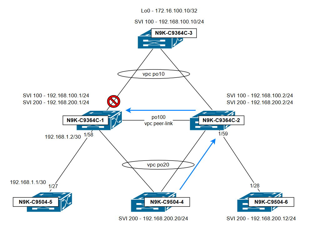
Conclusion:
N9K-C9364C-1 drops traffic due to the vPC loop avoidance rule: Traffic received over the vPC peer-link cannot be forwarded out any vPC port-channel that is active on both switches."To avoid this issue, make sure the administrative status of the SVIs is consistent on both switches and that their configurations are symmetrical.
b) Routed Traffic from Orphan to vPC Host is Affected
Considering the same scenario where SVI 200 is shut down on N9K-C9364C-2, but remains active on N9K-C9364C-1. A ping from N9K-C9504-6 (VLAN 200) to N9K-C9364C-3 (VLAN 100) is unsuccessful.
N9K-C9504-6# ping 192.168.100.10 packet-size 1030 count 100 timeout 0
PING 192.168.100.10 (192.168.100.10): 1030 data bytes
Request 0 timed out
Request 1 timed out
Request 2 timed out
---- snip -----
Request 97 timed out
Request 98 timed out
Request 99 timed out

--- 192.168.100.10 ping statistics ---
100 packets transmitted, 0 packets received, 100.00% packet loss
N9K-C9504-6#
A colored ping (a ping with a specified MTU size) is used to trace the path taken by this traffic:
N9K-C9364C-2# show interface eth1/59 counters detailed all | i "1024 to|Eth" ; sh int port-channel 10 counters detailed all | i "1024 to|po" ; sh int port-channel 100 counters detailed all | i "1024 to|po"
Ethernet1/59
52. Rx Packets from 1024 to 1518 bytes: = 100 <<<----- Ingress port to N9K-C9504-6
60. Tx Packets from 1024 to 1518 bytes: = 0
port-channel10
52. Rx Packets from 1024 to 1518 bytes: = 0
60. Tx Packets from 1024 to 1518 bytes: = 0
port-channel100
52. Rx Packets from 1024 to 1518 bytes: = 0
60. Tx Packets from 1024 to 1518 bytes: = 100 <<<----- Egress po100 (vPC peer-link)
N9K-C9364C-2#
N9K-C9364C-1# show interface port-channel 10 counters detailed all | i "1024 to|po" ; sh int port-channel 100 counters detailed all | i "1024 to|po"
port-channel10
52. Rx Packets from 1024 to 1518 bytes: = 0
60. Tx Packets from 1024 to 1518 bytes: = 0 <<<----- Expected egress vPC po10. No packets!!!
port-channel100
52. Rx Packets from 1024 to 1518 bytes: = 100 <<<----- Ingress po100 (vPC peer-link)
60. Tx Packets from 1024 to 1518 bytes: = 0
N9K-C9364C-1#
Even though the traffic arrives at N9K-C9364C-1 through the vPC peer link, it is not forwarded to vPC port-channel 10. This is because the egress_vsl_drop bit is set to 1 for this vPC, which happens when the same vPC port-channel is operational on the peer switch (on this case N9K-C9364C-2).
N9K-C9364C-1# show system internal eltm info interface Po10 | i i vsl
egress_vsl_drop = 1
N9K-C9364C-1#
N9K-C9364C-1# show system internal vpcm info interface Po10 | i "Peer stat|Inform|vPC sta"
IF Elem Information:
MCECM DB Information:
vPC state: Up Old Compat Status: Pass
vPC Peer Information:
Peer state: Up <<<------------- vPC 10 up on peer
PSS Information:
vPC state: Up Old Compat Status: Pass
vPC Peer Information:
Peer state: Up <<<------------- vPC 10 up on peer
Shared Database Information:
Application database Information:
Lock Information:
N9K-C9364C-1#
Topology illustrating the traffic flow and the point at which it is dropped:
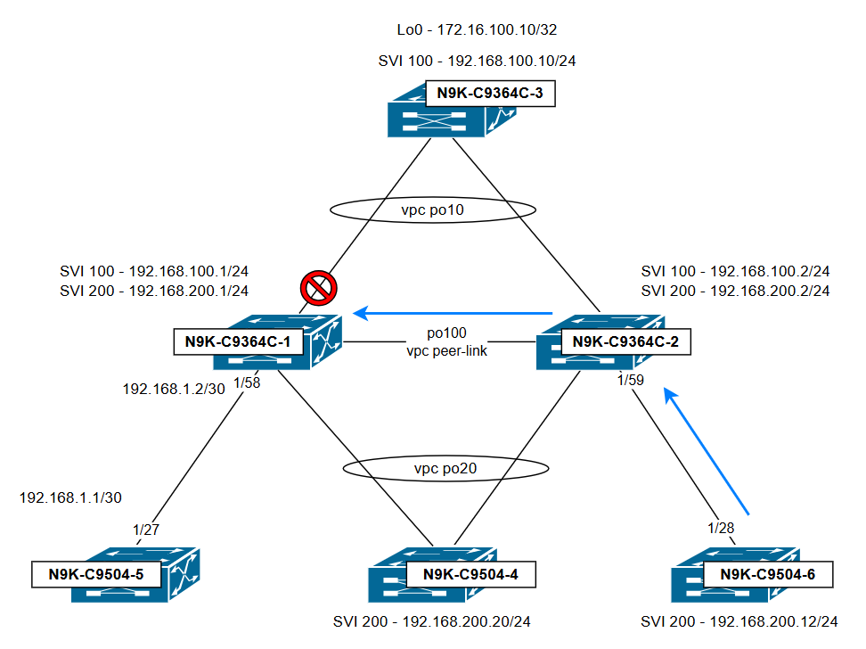
Conclusion:
Even though traffic originates from an orphan host connected to N9K-C9364C-2, it is dropped by N9K-C9364C-1 due to the vPC loop avoidance rule: Traffic received over the vPC peer-link cannot be forwarded out any vPC port-channel that is active on both switches. Whether the ingress port on the peer switch is a vPC or orphan port is irrelevant; what matters is that the traffic enters via the vPC peer-link and is destined for a vPC that is active on both switches. To avoid this issue, make sure the administrative status of the SVIs is consistent on both switches and that their configurations are symmetrical.
Scenario 2: All vPCs and SVIs are Up - Next Hop Points to the vPC Peer
In this scenario, all SVIs and vPC port-channels within the vPC domain are up. However, N9K-C9504-5, which is connected to N9K-C9364C-1 via a Layer 3 interface, is unable to ping Loopback 0 on N9K-C9364C-3.
A traceroute from N9K-C9504-5 indicates that the packet first reaches its immediate next hop at 192.168.1.2, and then proceeds to 192.168.100.2, which is associated with N9K-C9364C-2.
N9K-C9504-5# traceroute 172.16.100.10
traceroute to 172.16.100.10 (172.16.100.10), 30 hops max, 40 byte packets
1 192.168.1.2 (192.168.1.2) 1.338 ms 0.912 ms 0.707 ms
2 192.168.100.2 (192.168.100.2) 0.948 ms 0.751 ms 0.731 ms
3 * * *
4 * * *
N9K-C9504-5#
Next hop verification from N9K-C9364C-1 (the initial hop for this traffic) shows that the destination is reachable through 192.168.100.2, which corresponds to SVI 100 on N9K-C9364C-2.
N9K-C9364C-1# show ip route 172.16.100.10
IP Route Table for VRF "default"
'*' denotes best ucast next-hop
'**' denotes best mcast next-hop
'[x/y]' denotes [preference/metric]
'%<string>' in via output denotes VRF <string>

172.16.100.0/24, ubest/mbest: 1/0
*via 192.168.100.2, [1/0], 00:05:05, static
N9K-C9364C-1#
A colored ping (a ping with a specified MTU size) is used to trace the path taken by this traffic:
N9K-C9364C-1# show interface e1/58 counters detailed all | i "1024 to|Eth" ; sh int port-channel 100 counters detailed all | i "1024 to|po" ; sh int port-channel 10 counters detailed all | i "1024 to|po"
Ethernet1/58
52. Rx Packets from 1024 to 1518 bytes: = 100 <<<----- Ingress Eth1/58
60. Tx Packets from 1024 to 1518 bytes: = 0
port-channel100
52. Rx Packets from 1024 to 1518 bytes: = 0
60. Tx Packets from 1024 to 1518 bytes: = 100 <<<----- Egress po100 (vPC peer-link)
port-channel10
52. Rx Packets from 1024 to 1518 bytes: = 0
60. Tx Packets from 1024 to 1518 bytes: = 0
N9K-C9364C-1#
N9K-C9364C-2# sh int port-channel 100 counters detailed all | i "1024 to|po" ; sh int port-channel 10 counters detailed all | i "1024 to|po"
port-channel100
52. Rx Packets from 1024 to 1518 bytes: = 100 <<<----- Ingress po100 (vPC peer-link)
60. Tx Packets from 1024 to 1518 bytes: = 0
port-channel10
52. Rx Packets from 1024 to 1518 bytes: = 0
60. Tx Packets from 1024 to 1518 bytes: = 0 <<<----- Egress vPC po10, no packets!!!
N9K-C9364C-2#
Even though the traffic arrives at N9K-C9364C-2 through the vPC peer link, it is not forwarded to vPC port-channel 10. This is because the egress_vsl_drop bit is set to 1 for this vPC, which happens when the same vPC port-channel is operational on the peer switch (on this case N9K-C9364C-1).
N9K-C9364C-2# show system internal eltm info interface Po10 | i i vsl
egress_vsl_drop = 1
N9K-C9364C-2#
N9K-C9364C-2# show system internal vPCm info interface Po10 | i "Peer stat|Inform|vPC sta"
IF Elem Information:
MCECM DB Information:
vPC state: Up Old Compat Status: Pass
vPC Peer Information:
Peer state: Up <<<------------- vPC 10 up on peer
PSS Information:
vPC state: Up Old Compat Status: Pass
vPC Peer Information:
Peer state: Up <<<------------- vPC 10 up on peer
Shared Database Information:
Application database Information:
Lock Information:
N9K-C9364C-2#
Topology illustrating the traffic flow and the point at which it is dropped:
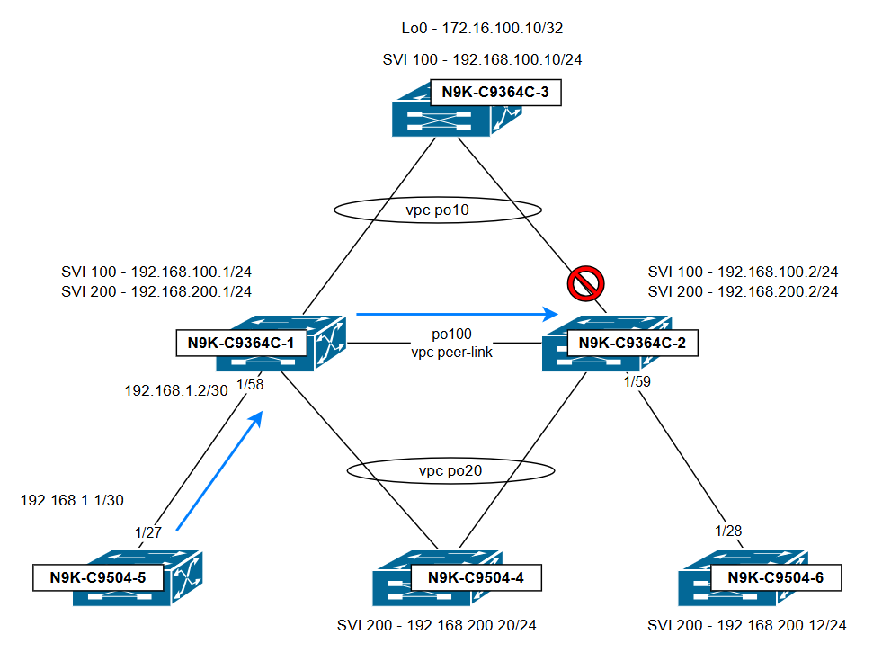
Conclusion:
The issue is observed because N9K-C9364C-1 uses N9K-C9364C-2 as the next hop, sending traffic across the vPC peer-link before it tries to exit through vPC 10. Traffic is dropped due to the vPC loop avoidance rule: Traffic received over the vPC peer-link cannot be forwarded out any vPC port-channel that is active on both switches. To avoid this issue, make sure that routes (dynamic or static) with a next hop through a vPC port-channel are configured on both vPC peer switches, so that traffic does not need to cross over the vPC peer-link and egress over a vPC.
Scenario 3: All vPCs and SVIs are Up - VPC Peer-gateway Feature is Off
On this scenario all SVIs and vPC port-channels are up on the vPC domain; however, the vPC peer-gateway feature is turned off. At this point, N9K-C9504-4 (VLAN 200) is unable to ping N9K-C9364C-3 (VLAN 100).
N9K-C9504-4# ping 192.168.100.10
PING 192.168.100.10 (192.168.100.10): 56 data bytes
Request 0 timed out
Request 1 timed out
Request 2 timed out
Request 3 timed out
Request 4 timed out

--- 192.168.100.10 ping statistics ---
5 packets transmitted, 0 packets received, 100.00% packet loss
N9K-C9504-4#
Next hop verification from N9K-C9504-4 shows that the destination is reachable through 192.168.200.2, which corresponds to SVI 200 on N9K-C9364C-2 and connected over vPC port-channel 20.
N9K-C9504-4# show ip route 192.168.100.10
IP Route Table for VRF "default"
'*' denotes best ucast next-hop
'**' denotes best mcast next-hop
'[x/y]' denotes [preference/metric]
'%<string>' in via output denotes VRF <string>

0.0.0.0/0, ubest/mbest: 1/0
*via 192.168.200.2, [1/0], 01:22:46, static
N9K-C9504-4#
N9K-C9504-4# show ip arp detail | i 192.168.200.2
192.168.200.2 00:08:05 a478.06de.7edb Vlan200 port-channel20 default
A colored ping (a ping with a specified MTU size) is used to trace the path taken by this traffic. Here the interface counters reveal that N9K-C9364C-1 receives the traffic from 192.168.200.20 to 192.168.100.10 over port-channel 20 and sends it to the vPC peer-link (port-channel100)
N9K-C9364C-1# show interface port-channel 20 counters detailed all | i "1024 to|po" ; sh int port-channel 10 counters detailed all | i "1024 to|po" ; sh int port-channel 100 counters detailed all | i "1024 to|po"
port-channel20
52. Rx Packets from 1024 to 1518 bytes: = 100   <<<----- Ingress vPC 20
60. Tx Packets from 1024 to 1518 bytes: = 0
port-channel10
52. Rx Packets from 1024 to 1518 bytes: = 0
60. Tx Packets from 1024 to 1518 bytes: = 0
port-channel100
52. Rx Packets from 1024 to 1518 bytes: = 0
60. Tx Packets from 1024 to 1518 bytes: = 100   <<<----- Egress po100 (vPC peer-link)
N9K-C9364C-1#
N9K-C9364C-2 receives the traffic over the vPC peer-link (port-channel100), but does not forward it to vPC port-channel 10.
N9K-C9364C-2# show int port-channel 20 counters detailed all | i "1024 to|po" ; sh int port-channel 10 counters detailed all | i "1024 to|po" ; sh int port-channel 100 counters detailed all | i "1024 to|po"
port-channel20
52. Rx Packets from 1024 to 1518 bytes: = 0
60. Tx Packets from 1024 to 1518 bytes: = 0
port-channel10
52. Rx Packets from 1024 to 1518 bytes: = 0
60. Tx Packets from 1024 to 1518 bytes: = 0   <<<----- Egress vPC po10, no packets!!!
port-channel100
52. Rx Packets from 1024 to 1518 bytes: = 100  <<<----- Ingress po100 (vPC peer-link)
60. Tx Packets from 1024 to 1518 bytes: = 0
N9K-C9364C-2#
Even though the traffic arrives at N9K-C9364C-2 through the vPC peer link, it is not forwarded to vPC port-channel 10. This is because the egress_vsl_drop bit is set to 1 for this vPC, which happens when the same vPC port-channel is operational on the peer switch (on this case N9K-C9364C-1).
Since peer-gateway is disabled, N9K-C9364C-1 can only route packets addressed to its own local MAC address. As a result, packets destined to a478.06de.7edb (MAC from N9K-C9364C-2) are forwarded by N9K-C9364C-1 via the vPC peer-link.
N9K-C9364C-1# show mac address-table add a478.06de.7edb
Legend:
* - primary entry, G - Gateway MAC, (R) - Routed MAC, O - Overlay MAC
age - seconds since last seen,+ - primary entry using vPC Peer-Link,
(T) - True, (F) - False, C - ControlPlane MAC, ~ - vsan
VLAN MAC Address Type age Secure NTFY Ports
---------+-----------------+--------+---------+------+----+------------------
* 100 a478.06de.7edb static - F F vPC Peer-Link(R)
* 200 a478.06de.7edb static - F F vPC Peer-Link(R)
N9K-C9364C-1#
Topology illustrating the traffic flow and the point at which it is dropped:
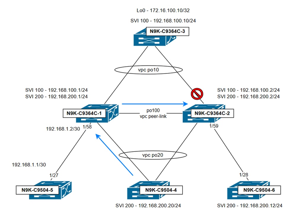
Conclusion:
If peer-gateway is enabled, routed traffic destined for the vPC peer’s MAC address is processed locally by programming the peer MAC as a gateway. This prevents the vPC peer-link from being used in the traffic path and avoids drops caused by the vPC loop avoidance rule. To prevent such issues, ensure that the vPC peer-gateway feature is enabled on the vPC domain.
Solution Overview
- Keep SVI configuration consistent on vPC VLANs.
Asymmetric Switched Virtual Interface (SVI) configurations between vPC peer switches can lead to critical traffic forwarding issues, including traffic blackholing. A common but unsupported practice that contributes to this condition is testing failover between vPC peers by shutting down SVIs on one side. This method creates an asymmetric SVI state that the Nexus vPC architecture does not support, resulting in traffic blackholing and forwarding failures. Make sure SVI configuration is always consistent on all vPC VLANs for which routing is needed.
- Enable peer-gateway on the vPC domain.
The peer-gateway feature is a critical enhancement in Cisco Nexus vPC deployments. When enabled on the vPC domain, it allows each vPC peer switch to accept and process packets destined for the virtual MAC address of the vPC peer. This means that either vPC peer can respond to gateway-bound traffic, regardless of which switch originally received the packet. Without peer-gateway enabled, certain types of traffic—such as packets sent to the default gateway MAC address—can be dropped if they arrive on one peer and would otherwise need to traverse the peer-link and exit a vPC member port. Make sure vPC peer-gateway is configured on the vPC domain.
Related Information
Understand Virtual Port Channel (vPC) Enhancements
Revision History
| Revision | Publish Date | Comments |
|---|---|---|
1.0 |
14-Oct-2025
|
Initial Release |
Contributed by Cisco Engineers
- Francini Maria Fernandez ZunigaTechnical Consulting Engineer
 Feedback
Contact Cisco
- Open a Support Case

- (Requires a Cisco Service Contract)