Introduction
This document describes how to troubleshoot and validate Wake on LAN (WoL) functionality on Cisco Catalyst 9500 Series.
Prerequisites
Requirements
Cisco recommends that you have knowledge of these topics:
- Cisco Catalyst 9500 Series switch configuration and architecture.
- LAN switching concepts, including VLANs, SVIs, and port-channels.
- Directed broadcast and network broadcast concepts in IPv4 networking.
- Packet capture and analysis using Cisco monitor capture features and platform packet-forwarding CLI.
- Basic familiarity with troubleshooting tools such as Wireshark and endpoint configuration for WoL.
Components Used
The information in this document is based on these software and hardware versions:
- Cisco Catalyst 9500 Series, model C9500-48Y4C-A.
- Cisco Catalyst 9300 Series, model C9300-48T.
- WoL source and destination endpoints, including VMs and physical hosts.
- Cisco IOS XE 17.12.4 Version.
The information in this document was created from the devices in a specific lab environment. All of the devices used in this document started with a cleared (default) configuration. If your network is live, ensure that you understand the potential impact of any command.
Background Information
Wake on LAN (WoL) is a networking standard that allows a computer to be turned on or awakened by a network message, commonly known as a "magic packet".
In Cisco LAN environments, WoL typically relies on the correct forwarding of UDP broadcast or directed broadcast packets across VLANs and routed interfaces.
The methodology and workflow described in this document are effective for troubleshooting Wake on LAN issues on Catalyst 9500 Series switches.
Starting on 17.3.1 IP Directed Broadcast is disabled by default and the behavior is documented under this defect: Cisco bug IDCSCvy85946.
This scenario resembles WoL packets not being delivered as expected between source server and destination endpoint VLANs.
This document provides a detailed workflow for validating, capturing, and troubleshooting WoL packet flow across Catalyst 9500 platforms, including all relevant CLI commands, configurations, and detailed output explanations.
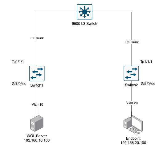 Figure 1. Network Topology Diagram
Troubleshoot
1. Symptom and Initial Analysis
The WoL packets (magic packets) sent from the server were not waking the endpoint devices as expected.
The troubleshooting process involved validating that packets were being sent, received, and correctly forwarded through the network.
Initial checks and commands helped confirm the symptoms and collect baseline data, ip network-broadcast and ip directed-broadcasts commands were added under SVI 10 and 20 to resolve the issue:
Step 1: Validate Interface and VLAN Configuration
c9500#show run int vlan 10
interface Vlan10
 ip address 192.168.10.1 255.255.255.0
 ip network-broadcast
 ip directed-broadcasts
end
c9500#show run int vlan 20
interface Vlan20
 ip address 192.168.20.1 255.255.255.0
 ip network-broadcast
 ip directed-broadcasts
end

Note: The ip network-broadcast command enables the ingress interface to receive and accept the network-prefix-directed broadcast packets.
The ip directed-broadcasts command enables directed broadcast-to-physical broadcast translation on the interface
Step 2: Verify WoL Packet Transmission from Source
c9500#sh ip arp 192.168.10.100
Example output:
Protocol  Address          Age (min)  Hardware Addr   Type   Interface
Internet  192.168.10.100           136   aaaa.aaaa.aaaa  ARPA   Vlan10
Switch1#show mac address-table address aaaa.aaaa.aaaa
Example output:
Vlan    Mac Address       Type        Ports
10     aaaa.aaaa.aaaa    DYNAMIC     Gi1/0/44
2. Monitor and Capture WoL Packets
To confirm if WoL packets are being correctly sent and traversing the network, use the monitor capture feature and analyze buffer contents.
Step 1: Configure and Check Monitor Capture Parameters on Switch1
Switch1#show mon cap cap parameter
Example output:
monitor capture cap interface GigabitEthernet1/0/44 BOTH
monitor capture cap buffer size 100
monitor capture cap limit pps 1000
monitor capture cap match any
Step 2: Configure and Check Monitor Capture Parameters on 9500 Switch:
c9500#show mon cap cap parameter
Example output:
monitor capture cap control-plane BOTH
monitor capture cap buffer size 100
monitor capture cap limit pps 1000
monitor capture cap match any
Note: We are using control plane capture as this traffic needs to be punted to CPU for further processing.
Punt: Ingress protocol control packets are intercepted by DP and sent to the CP (CPU) for processing
Inject: CP (CPU) generated protocol packets are sent to the DP to egress out on IO interface(s)
Step 2: Review Buffer for WoL Packets
Switch1#sh mon cap cap buffer brief | i 192.168.20.255
Example output (multiple instances show reliability):
3975   3.002758  192.168.10.100 -> 192.168.20.255  WOL 148 MagicPacket for bb:bb:bb:bb:bb:bb (bb:bb:bb:bb:bb:bb)
17103  16.246445  192.168.10.100 -> 192.168.20.255  ECHO 148 Request
...
15864  14.870272  192.168.10.100 -> 192.168.20.255  WOL 148 MagicPacket for bb:bb:bb:bb:bb:bb (bb:bb:bb:bb:bb:bb)
Step 3: Capture and Export for Detailed Analysis
device#monitor capture cap export location flash:cap.cap
3. Analyze Packet Forwarding Path Using Platform CLI
Use platform hardware forwarding commands to validate how the WoL packets are being processed and forwarded by the hardware.
Step 1: Check Forwarding Summary for Last Packet
device#show platform hardware fed switch 1 forward last summary
Example output excerpt:
Input Packet Details:
###[ Ethernet ]###
  dst       = bb:bb:bb:bb:bb:bb
  src=aa:aa:aa:aa:aa:aa
  type      = 0x8100
###[ 802.1Q ]###
     vlan      = 10
###[ IP ]###
        src=192.168.10.100
        dst       = 192.168.20.255
        proto     = udp
###[ UDP ]###
           sport     = 56826
           dport     = discard
           len       = 110
           chksum    = 0x7813
###[ Raw ]###
              load      = 'FF FF FF FF FF FF 4C D7 17 86 13 A5 ...'
Egress:
   Possible Replication:
       Port                  : TenGigabitEthernet1/1/1
Output Packet Details:
   Port                      : TenGigabitEthernet1/1/1
###[ Ethernet ]###
  dst       = bb:bb:bb:bb:bb:bb
  src=aa:aa:aa:aa:aa:aa
  type      = 0x8100
...
This output confirms that the WoL packet is being processed and forwarded by the switch hardware.
Step 2: Validate Packet Traversal on Distribution/Core Switches
device#show platform hardware fed switch 2 forward last summary
Example output (on distribution switch):
Input Packet Details:
###[ Ethernet ]###
  dst       = bb:bb:bb:bb:bb:bb
  src=aa:aa:aa:aa:aa:aa
  type      = 0x8100
###[ 802.1Q ]###
     vlan      = 10
###[ IP ]###
        src=192.168.10.100
        dst       = 192.168.20.255
        proto     = udp
...
Output Packet Details:
   Port                      : HundredGigE2/0/51
###[ Ethernet ]###
  dst       = bb:bb:bb:bb:bb:bb
  src=aa:aa:aa:aa:aa:aa
  type      = 0x8100
...
This confirms that the WoL packet is being forwarded to the next-hop/core switch.
4. Verify WoL Packet Reception on Endpoint VLAN
Check that the magic packet is received at the endpoint VLAN and not being dropped by the switch. Use packet capture and platform hardware commands.
Step 1: Monitor Magic Packet Arrival on Destination VLAN
device#sh mon cap cap buffer brief | i 192.168.20.255
Example output:
15864 14.870272 192.168.10.100 -> 192.168.20.255 WOL 148 MagicPacket for bb:bb:bb:bb:bb:bb (bb:bb:bb:bb:bb:bb)
A consistent appearance of WoL packets in the capture indicates successful transmission through the network.
5. Endpoint and Server Considerations
WoL functionality also depends on correct endpoint configuration. During troubleshooting, it was found that packet transmission and reception reliability can be impacted by server settings, endpoint readiness, or hypervisor limitations (if virtualized). Capturing packets at the endpoint using tools like Wireshark is recommended to verify successful delivery.
Example Wireshark capture output (summarized):
Ethernet II, Src: VMware_aa:aa:aa (aa:aa:aa:aa:aa:aa), Dst: Cisco_cc:cc:cc (bb:bb:bb:bb:bb:bb)
Type: IPv4 (0x0800)
Internet Protocol Version 4, Src: 192.168.10.100, Dst: 192.168.20.255
User Datagram Protocol, Src Port: 63082, Dst Port: 9
UDP payload (102 bytes)
Discard Protocol
    Data: ffffffffffff4cd7178667ed...
This confirms the magic packet is received at the destination subnet.
6. Common Issues and Additional Observations
- Inconsistent WoL packet delivery is seen if there are drops or exceptions in ASIC counters.
- Some packets are dropped due to control-plane policing (CoPP) or incorrect interface configurations (for example, missing
no ip redirects).
- Ensuring
ip directed-broadcast is enabled is critical for WoL to function across routed interfaces.
- Testing with both network and broadcast addresses is helpful to determine where packets are dropped.
Related Information
 Feedback