Introduction
This document describes basics of Forwarding Error Correction (FEC) and how to validate the feature on the Catalyst 9000-family of switches.
Prerequisites
Requirements
Cisco recommends that you have knowledge of these topics:
- Catalyst 9000-series switches
- Optical Transceivers
Background Information
What is FEC?
FEC is a technique used to detect and correct a certain number of errors in a bitstream by appending redundant bits and error-checking code to the message block before transmission. The addition contains sufficient information on the actual data to enable the FEC decoder at the receiver end to reconstruct the original message. The FEC decoder can identify the bits received in error and correct them. It then removes the redundant bits before passing the message to the upper layers of the network. Because the FEC decoder uses only the redundant bits to detect and correct errors, it does not request retransmission of the entire errored frame, saving bandwidth that would otherwise be used for retransmission.
FEC provides a way for networks to increase data rate while maintaining an acceptable bit error rate(BER). There are trade-offs, however. The improvement is the result of adding overhead in the form of error-correcting parity bits, which consumes some of the available bandwidth. In general, the higher the coding gain, the greater the number of parity bits, which increases the size of the codewords. FEC decoders need to receive the full codeword before they can act on it. Stronger FEC algorithms offer higher coding gains, but they require larger codewords, and larger codewords increase latency.
Why do fiber optic networks need FEC?
The growing popularity of cloud computing, streaming video, and social networking has massively increased internet traffic. To meet the skyrocketing bandwidth demand, the optical networking industry has pushed data rates to 100 Gbps and beyond. Optical transmission is vulnerable to various sources of signal degradation, including chromatic dispersion, modal dispersion, polarization mode dispersion, and noise.
In the real world, the ability of an optical receiver to resolve information is impacted by the presence of noise. As a result, a receiver cannot accurately resolve all bits, introducing errors into the data transmission. This problem is exacerbated at higher speeds because receiver filter bandwidths must be widened to allow the faster signals and must also then allow more noise energy to pass through. Fortunately, FEC can help compensate for this problem. Although the technique cannot correct all errors under all network conditions, when properly specified, it can help network operators run at higher transmission rates while maintaining target Bit Error Ratios (BERs), all while using less expensive optics.
Catalyst 9000-series switches support 2 types of FECs:
FC-FEC
RS-FEC
FC-FEC configuration value is cl74
RS-FEC has two configuration values depending of the speed of the link:
25GBs or 50GBs: cl108
100GBs: cl91
How we negotiate FEC value and when FEC is required?
FEC is required at 25GBs speed or higher when the cable length is longer than 2 meters.
The FEC block that performs the coding and decoding is often in the ASIC of the switch/router. In other cases, for example in certain 100G optics, it is in the module itself.
FEC is enabled in auto mode by default; however, there could be other FEC clauses for specific application protocols that can be supported by the host software. The user can decide to enable these, depending on their specific application.
Topology
 Topology 1
Configuration and Verification
Configuration:
Cat9300X-24Y(config)# interface tw1/1/2
Cat9300X-24Y(config-if)#fec ?
auto    Enable FEC Auto-Neg
cl108   Enable clause108 with 25G
cl74    Enable clause74 with 25G
off     Turn FEC off

Cat9300X-24Y(config-if)#fec auto
Verification:
Cat9300X-24Y# show running-config interface tw1/1/2
!
interface TwentyFiveGigE1/1/2
end
The absence of FEC configuration indicates that FEC is set to auto or you can check the status of the interface
Cat9300X-24Y# show interface tw1/1/2
TwentyFiveGigE1/1/2 is up, line protocol is up (connected)
--snip--
  Full-duplex, 25Gb/s, link type is force-up, media type is SFP-25GBase-SR
  Fec is auto              < -- The configured setting for FEC is displayed here
  input flow-control is on, output flow-control is off
  ARP type: ARPA, ARP Timeout 04:00:00
--snip--
The mismatch of FEC on both sides of the link can break the connection between the devices even if everything else is good.
Example:
Cat9300X-24Y#show running-config interface tw1/1/2
Building configuration...

Current configuration : 47 bytes
!
interface TwentyFiveGigE1/1/2
 fec cl74
end

Cat9300X-24Y#show interface tw1/1/2
TwentyFiveGigE1/1/2 is down, line protocol is down (notconnect)
|
Cat9300X-48X#show running-config interface tw1/1/6
Building configuration...

Current configuration : 37 bytes
!
interface TwentyFiveGigE1/1/6
end


Cat9300X-48X#show interface tw1/1/6
TwentyFiveGigE1/1/6 is  down, line protocol is down (notconnect)
|
Cat9300X-24Y#show interfaces transceiver
If device is externally calibrated, only calibrated values are printed.
++ : high alarm, +  : high warning, -  : low warning, -- : low alarm.
NA or N/A: not applicable, Tx: transmit, Rx: receive.
mA: milliamperes, dBm: decibels (milliwatts).

                                             Optical   Optical
             Temperature  Voltage  Current   Tx Power  Rx Power
Port         (Celsius)    (Volts)  (mA)      (dBm)     (dBm)
---------    -----------  -------  --------  --------  --------
Twe1/1/6     37.4       3.29       7.4      -0.4      -4.9
|
Cat9300X-48X#show interfaces transceiver
If device is externally calibrated, only calibrated values are printed.
++ : high alarm, +  : high warning, -  : low warning, -- : low alarm.
NA or N/A: not applicable, Tx: transmit, Rx: receive.
mA: milliamperes, dBm: decibels (milliwatts).

                                             Optical   Optical
             Temperature  Voltage  Current   Tx Power  Rx Power
Port         (Celsius)    (Volts)  (mA)      (dBm)     (dBm)
---------    -----------  -------  --------  --------  --------
Twe1/1/2     37.8       3.33       7.8      -0.8      -1.2
|
You can see that even with a receive good signal the port is down on both sides as the FEC configuration does not match. In this case, you need to match the FEC configuration, either choosing "auto" in both or "cl74".
While troubleshooting link problems take these steps:
1. Compatibility of the transceiver with the device
2. Compatibility between transceiver in the same link
3. Compatibility between the transceiver and the fiber cable in use
4. Negotiation between sites
4.1. Speed
4.2. FEC
FEC take more importance when we are connecting devices that are different. We see most problems when connected to 3rd party eqyuipment or host devices, could be UCSs or Nexus devices.
If FEC is left in default mode, both devices need to negotiate the FEC setting to be used and that could be a problem. Is better to manually set the FEC settings but it needs to match between both sides of the link.
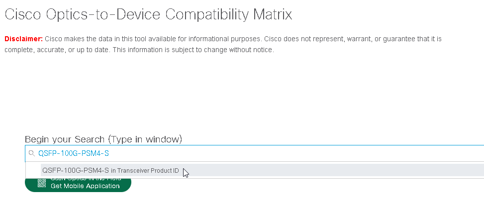
To see what FEC setting is allow on the transceiver you need to use the TMGMatrix:
https://tmgmatrix.cisco.com/
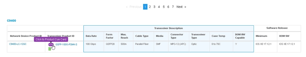
Once there you filter by transceiver PID or device:
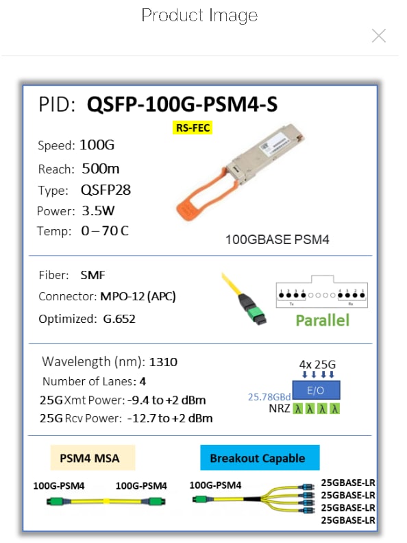
Then you click in the CUE card of the transceiver:
The CUE card shows all the data you need to know about the transceiver, including the FEC setting:
Related Information
 Feedback