Configuring Policy NAT on the RV160 and RV260
Available Languages
Objective
Introduction
Network Address Translation (NAT) operates on a router and enables private IP networks with nonregistered IP addresses to connect to the Internet. A router would act as an agent between the local network and the Internet (public network), which means that NAT translates the private addresses (internal network) into a single unique public IP address that would represent the entire group of computers to anything outside their network. This provides additional security by effectively hiding the entire internal network behind that one unique public IP address. NAT also helps conserve the use of IPv4 addresses due to a key problem of IPv4 depletion.
Policy NAT allows you to identify the public address for the address translation by specifying the source and destination address in an extended access list. One of the many ways that Policy NAT can be used is to map multiple private IP addresses to different WAN IP addresses.
In this document, we will configure Policy NAT by creating two new VLANs (VLAN 2 and VLAN 10) and attaching them to two different WAN IP addresses. You can specify the source and destination ports. Policy NAT allows you to create flexible NAT rules for advanced users. Please understand the capabilities of the feature and your use case before configuring the rules. Invalid settings may be accepted but they may not work. For most users, it is recommended to use the Port Forwarding or Static NAT instead.
To learn how to configure NAT and Static NAT on the RV160 and RV260, click here.
Applicable Devices
· RV160
· RV260
Software Version
· 1.0.0.13
VLAN Configuration
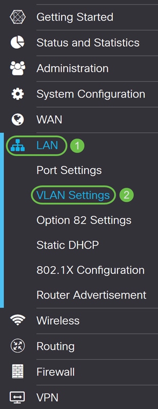
Step 1. Log into the web configuration page and navigate to LAN > VLAN Settings. In this example, we will be creating VLAN 2 and VLAN 10. Each of the VLANs will be in a different subnet following the format of 172.16.x.x/24.
Step 2. Click the Plus icon to create a new VLAN.

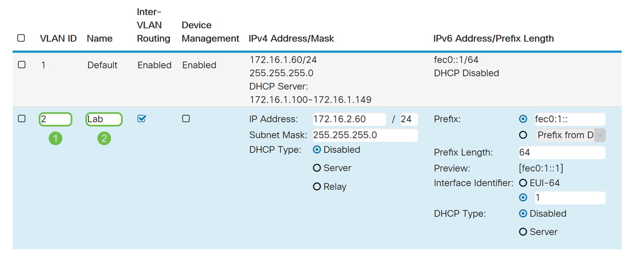
Step 3. Enter the VLAN ID (Range is 1-4093) and a name.
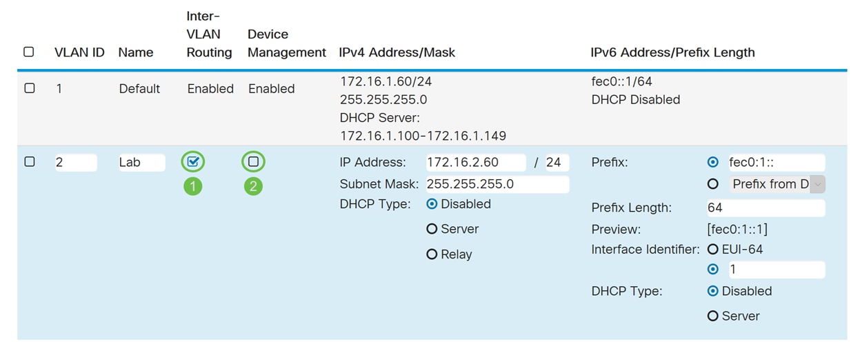
Step 4. Check the Enabled checkbox to enable Inter-VLAN routing and Device Management. In this example, we will only be enabling Inter-VLAN Routing. Having Inter-VLAN Routing enabled is useful because internal network administrators will be able to remotely access your devices to help troubleshoot your issues. This will reduce the time of having to constantly switch VLANs in order to access the devices.
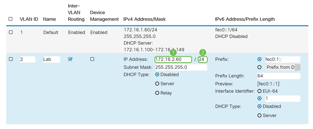
Step 5. Enter an IPv4 address and the subnet mask. In this example, we will be entering 172.16.2.60/24.
Note: The Subnet Mask field will auto adjust to the subnet mask you have entered in the / field.
Step 6. In the DHCP Type for IPv4, we will be leaving it as Disabled. This disables the DHCP IPv4 server on VLAN.
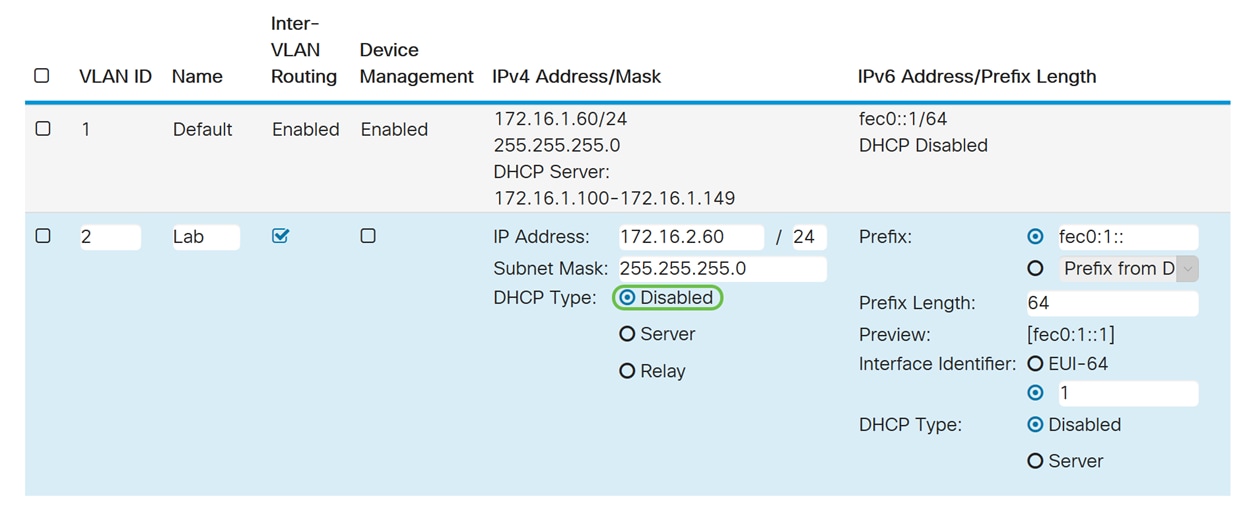
Step 7. In the IPv6 Address/Prefix Length section, enter in an IPv6 prefix and prefix length. We will be using the default IPv6 prefix and prefix length, fec0:1:: as the prefix and 64 as the prefix length.
Note: In this example, the rest of the options will be kept on default settings.
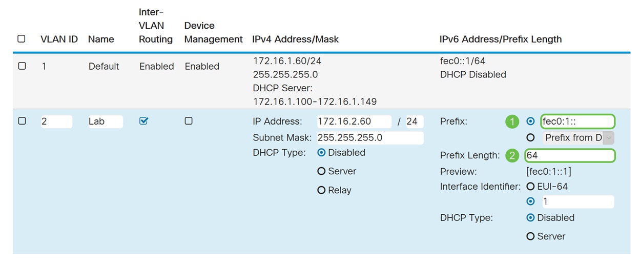
Step 8. Click Apply.

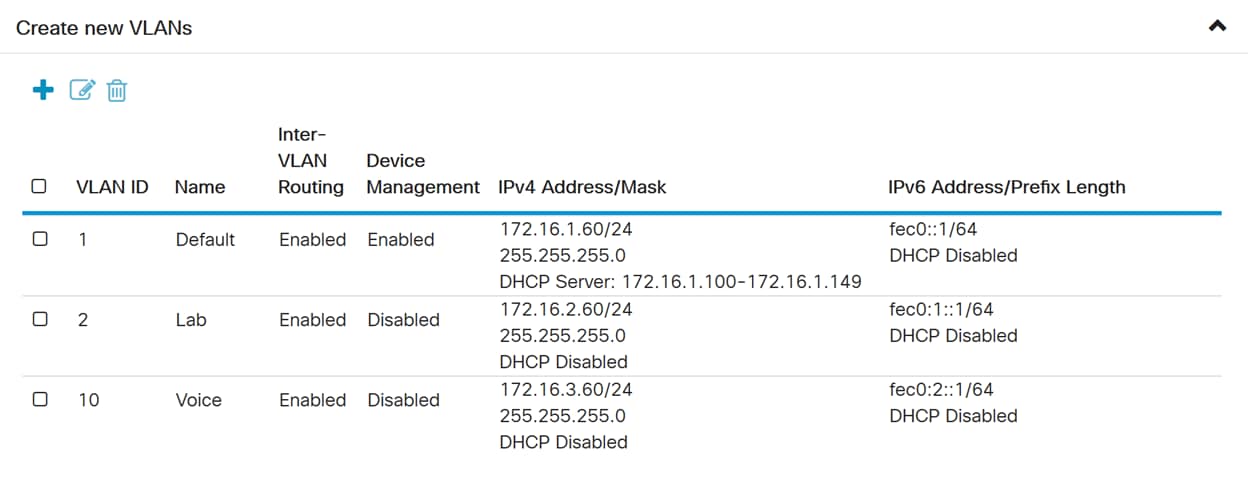
Note: If you want to create more VLANs, go back to step 1 of VLAN Configuration section. For this demonstration, we have created another VLAN. VLAN 10 with an IPv4 address of 172.16.3.60/24 and a IPv6 address prefix of fec0:2::/64.
Policy NAT Configuration
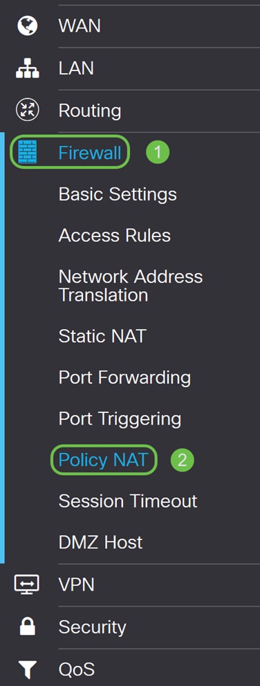
Step 1. Navigate to Firewall > Policy NAT.
Step 2. Click the Plus icon to add a new Policy NAT rule.
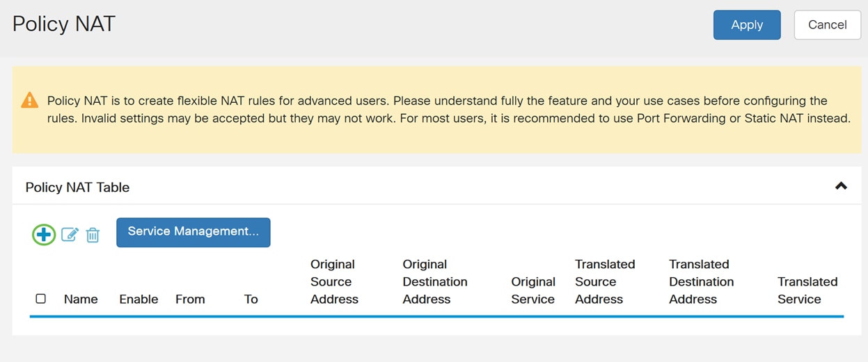
Step 3. Enter the name for the new Policy NAT rule.
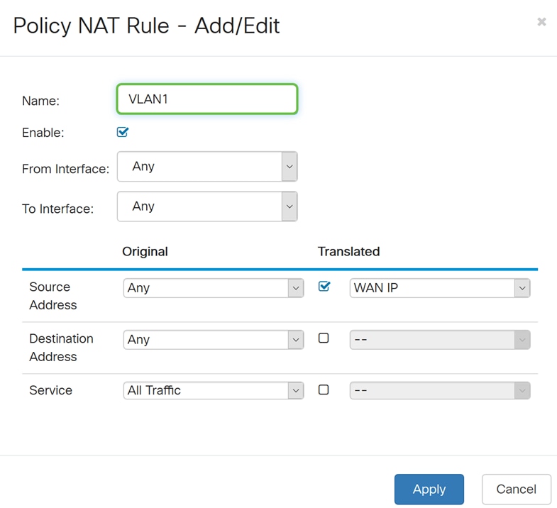
Step 4. Check Enable to enable the policy rule.
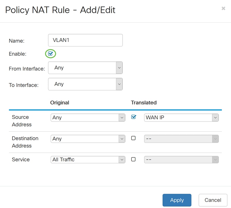
Step 5. In the From Interface field, select the interface from the drop-down list that the traffic is coming from. In this example, we will be selecting VLAN1.
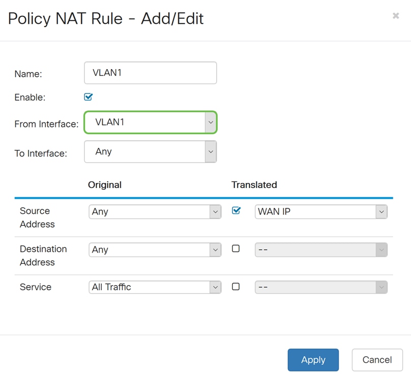
Step 6. In the To Interface field, select where the From Interface is going out. In this example, we will be selecting WAN as the To Interface.
Note: Dynamic Network Address Translation (DNAT) is an enhanced form of NAT which involves the router translating the IP address but not the port number. This dynamic approach is used for mapping the addresses of large numbers of internal computers to a few routable IP addresses. For DNAT, you should set the “To interface” as Any.
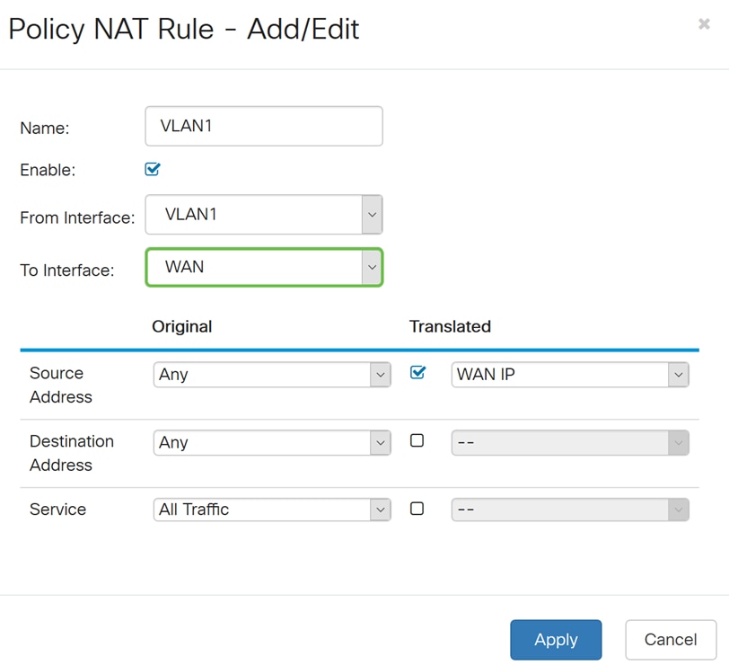
Step 7. In the Source Address section, select Any or Use a new IP Group to create a new address. Then select an option from the Translated Source Address drop-down list. We will be selecting Any as our Original Source Address and WAN IP as the translated public IP address for our VLAN 1.
Note: Skip to step 11 if you have selected Use a new IP group.
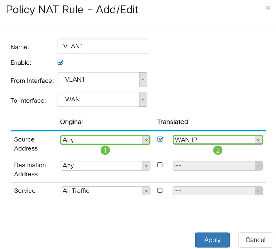
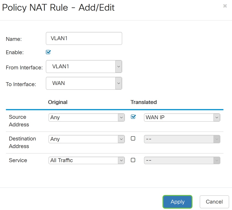
Step 8. Click Apply to add the new Policy NAT rule.
Note: The Destination Address and Service fields are left as default.
Step 9. Repeat steps 2-6 for the next VLAN. We will be configuring VLAN 2 to have a different WAN IP address.
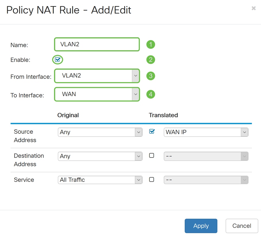
Step 10. Select Any as the Original Source Address and Use a new IP Group as the Translated Source Address option from the drop-down list.
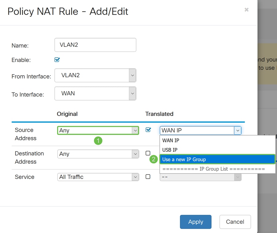
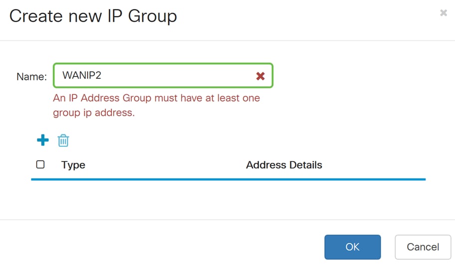
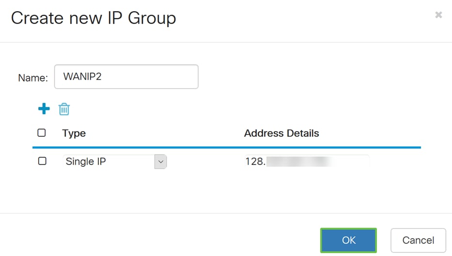
Step 11. A Create new IP Group window will appear. Enter a name for the WAN IP group.
Note: A message will display “An IP Address Group must have at least one group IP address.” This is configured in the next step.
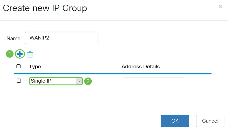
Step 12. Click the Plus icon to add a Single IP, IP Address Subnet, or IP Address Range. For this example, we will be selecting Single IP from the drop-down list because we want to translate the VLAN to a single IP address.
Step 13. In the Address Details field, enter in the second WAN IP address that you have.
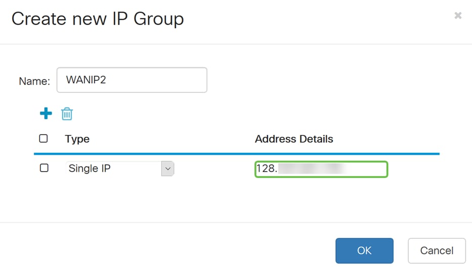
Step 14. Click OK to create the new IP group.
Step 15. Click Apply to add the new Policy NAT rule.
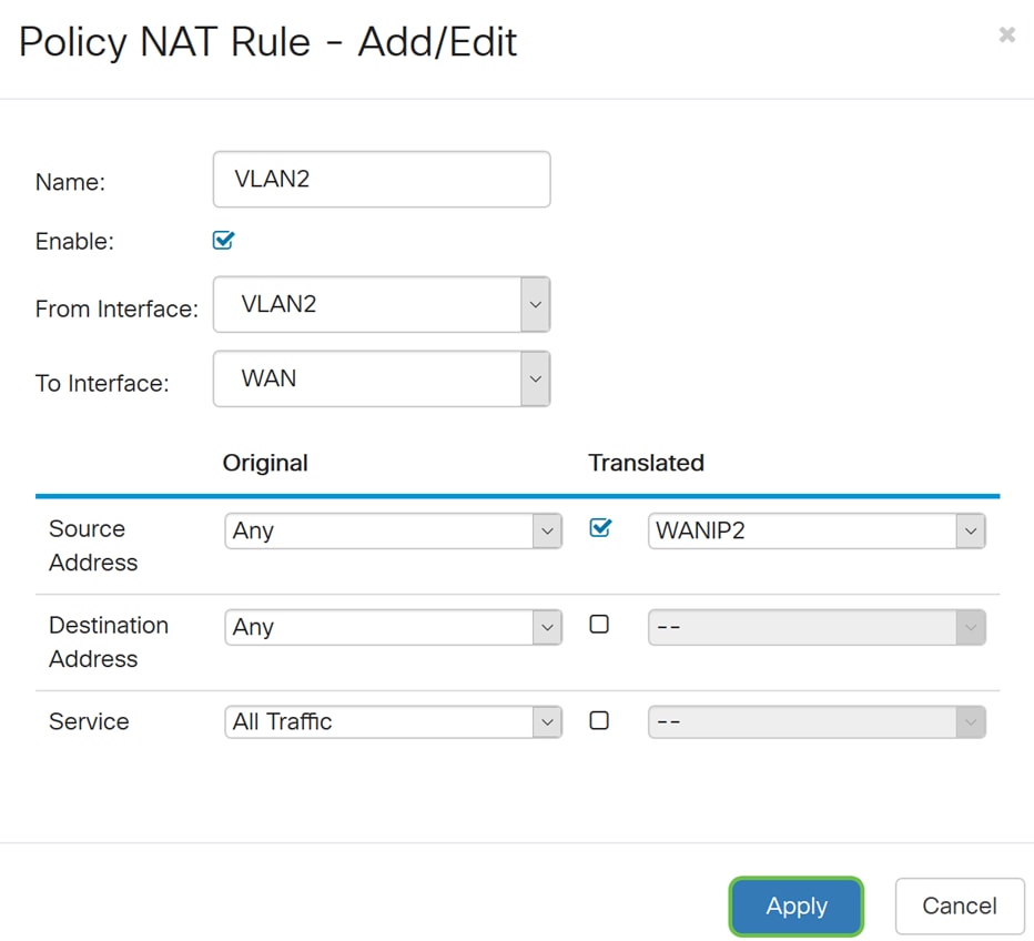
Note: If you have more VLANs to add that requires new WAN IP address, repeat steps 9-15.
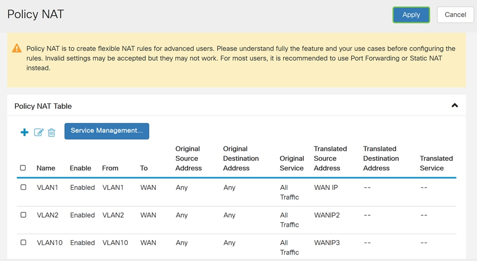
Step 16. Click Apply to apply the configuration.
Conclusion
You should have now successfully configured Policy NAT. Traffic going out from each of the VLANs should be showing up as a different WAN IP address. This is an example of one possible way of configuring Policy NAT.
 Feedback