Introduction
This document describes how to configure Power Policy for UCS X9508 chassis.
Components Used
For this demonstration, this is the setup:
One UCS X9508 Chassis connected to a pair of 6400 series Fabric Interconnect in IMM mode, managed by the Cisco Intersight SaaS instance.
The same information applies to the UCS X9508 Chassis managed by Cisco Intersight Virtual Appliances.
The information in this document was created from the devices in a specific lab environment. All of the devices used in this document started with a cleared (default) configuration. If your network is live, ensure that you understand the potential impact of any command.
Scenario
The UCS X9508 Chassis uses the concept of Chassis Profiles as a construct that defines a set of policies, including power, cooling and management, for a UCS chassis. While Server Profiles are more commonly used and discussed, Chassis Profiles serve a similar purpose at the chassis level.
By default, the UCS X-Series chassis does not have a Chassis Profile assigned, however, it uses certain preconfigured default policy values required to get the chassis up and running. To fit the chassis capabilities to suit the power specifics of an environment, cooling and management needs, the configuration of a Chassis Profile will be required.
This demonstration will focus on Chassis Power policies, enabling the configuration of power redundancy and power allocation for chassis.
Configure Power Policy
To configure Chassis Power Policy, log into the Intersight instance.
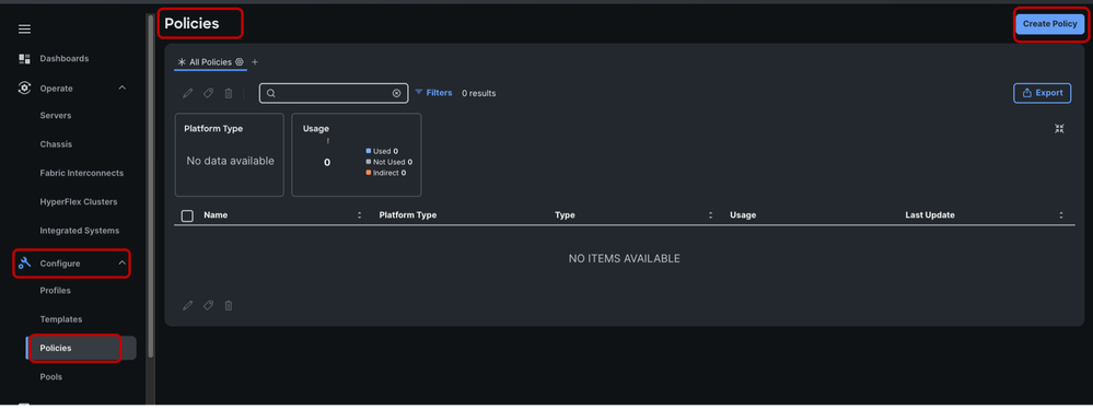
Under the Configure section, click Policies. In the Policies window, select Create Policy.
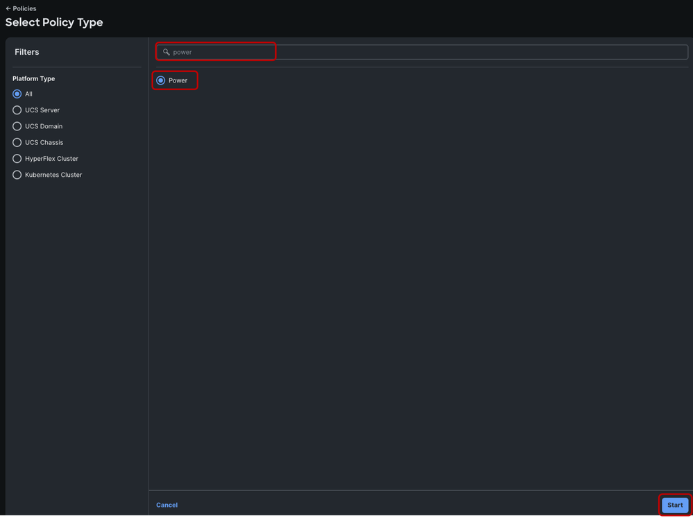
In the search bar, search for “power”.
Select the Power radio button and click Start.
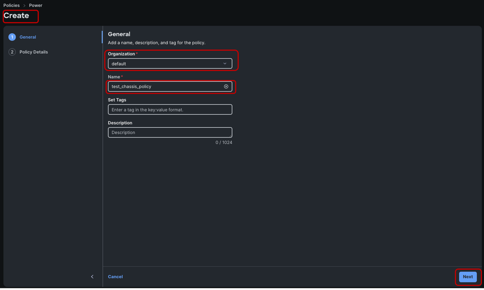
In the Create window, choose your desired Organization, name the power policy and click Next.
When All platforms option is selected, a single policy is created for the chassis and the available server.
It is recommended to have separate policies to avoid confusion and overlapping settings.
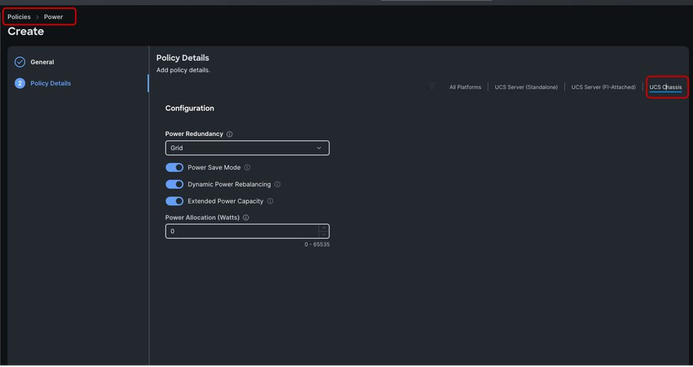
Select the UCS Chassis option on the top right.
Power redundancy modes:
The X9508 chassis supports up to 6 AC power supplies (PSUs), with the minimum configuration of 2 PSUs required. They are Titanium certified 2800W capable AC Power Supply Units (PSUs) that support input power from AC sources.
The PSU population and redundancy modes determine how much total power can be consumed without power faults due to PSU output loss. Power allocation will have an implicit cap at max value. Total power is still shared across all populated PSUs.
PSUs are redundant and load-sharing and can be used in these power modes:
- Non-redundant configuration: the system might go down with the loss of any supply or power grid associated with any particular chassis. We do not recommend operating the system in non-redundant mode in a production environment.
- N+1 configuration: the chassis contains a total number of power supplies to satisfy system power requirements, plus one additional power supply for redundancy.
- N+2 configuration: the chassis contains a total number of power supplies to satisfy system power requirements, plus two additional power supplies for redundancy.
- Grid configuration (also known as N+N): Each set of three PSUs has its own input power circuit, so each set of PSUs is isolated from any failures that might affect the other set of PSUs. If one input power source fails, causing a loss of power to three power supplies, the surviving power supplies on the other power circuit continue to provide power to the chassis.
Please review the Cisco UCS X9508 Server Chassis Installation Guide for more information: https://www.cisco.com/c/en/us/td/docs/unified_computing/ucs/x/hw/x9508/install/b-ucs-x9508-install/m-ucsx-9508-chassis-overview.html
This table helps to clarify the total and per-PSU maximum power based on the redundancy mode and PSU population (with none in standby):
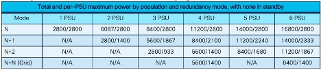
The default Power Redundancy mode is set to Grid, and the chassis for this demonstration is not fully populated. Grid redundancy will be able to provide sufficient power allocation to the servers prior to server power profiling, which will be explained later.
Cisco implemented a feature called "E-brake". This is a hardware-based throttling mechanism controlled by the Chassis Management Controller or CMC on the IFM. This can be triggered if grid power is lost and the server workloads are near maximum power utilization and load is in the extended power range. This might cause the server’s power to throttle until grid power is restored. Servers in throttling state will remain online, however, with possible performance degradation due to less power delivered to the server CPU. Once the load is less than the chassis' available power, the emergency brake is released, and normal throttling is used to maintain power under the new limit.
During the initial discovery of all servers in a fully populated chassis, it is recommended to temporarily change the power redundancy policy to N+1 prior to the servers running the power profile policy. After server discovery, the power redundancy policy can be changed to the previously configured policy (that is, Grid) without impact to the chassis or servers.
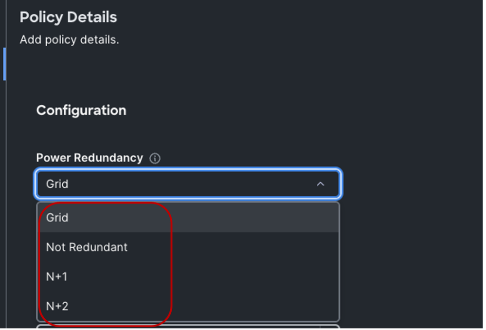
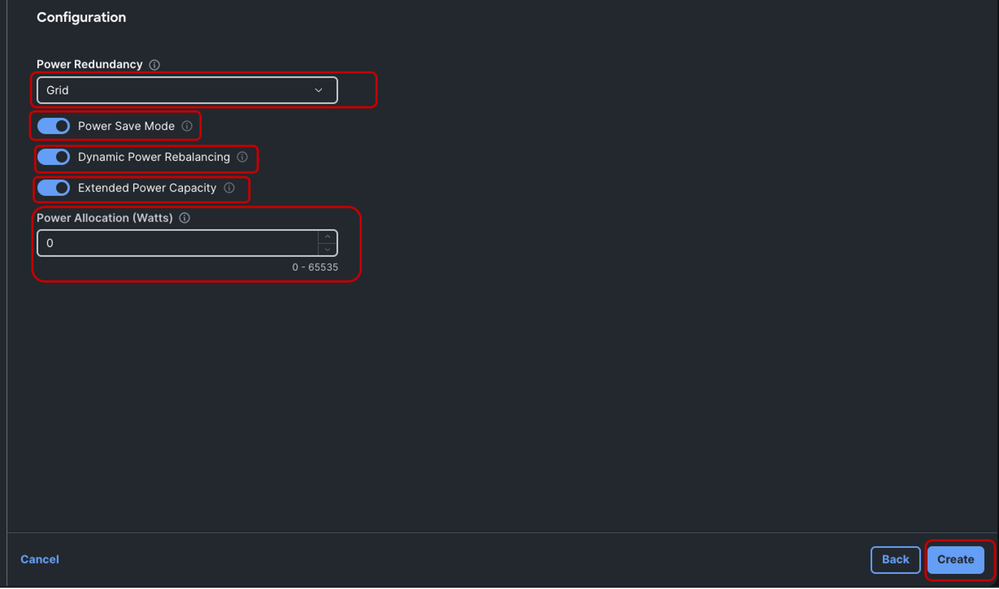
Power Redundancy:
The Power Redundancy mode determines the number of PSUs the chsasis keeps as redundant and the default is Grid mode.
Power Save Mode:
The Power Save Mode, which is enabled by default, allows unneeded power supplies to be turned off to improve efficiency. This can be enabled or disabled depending on the system needs.
Dynamic Power Rebalancing:
Dynamic power rebalancing will re-allocate power between servers if they are competing for power in a power constrained environment. It’s recommended to leave this enabled unless you have specific need to disable power rebalancing.
Extended Power Capacity:
When operating with any redundant power mode, the Extended Power Capacity option allows the total power allocation/consumption to be increased by 15%.
As an example, in a chassis set up with a total of 6 PSUs having power redundancy mode configured as Grid, each PSU provides 1400Watts which corresponds to 50% PSU allocation. In this scenario, without Extended Power Capacity, the total workload is capped at 8400Watts.
However, with Extended Power Capacity enabled, the workload cap increases to 9660Watts. This translates to 15% more power per PSU, boosting each to 1610Watts or 57.5% allocation per PSU.
Note that Extended Power Capacity option is not configurable if a chassis power redundancy mode is set to Not Redundant.
Power Allocation (Watts)
The Power Allocation field enables configuration of a maximum power value that a chassis can consume. The value can range from minimum of system requirement to maximum of available power. Deploying a policy with a Power Allocation of “0” will enable the chassis to utilize all available power according to the Power Redundancy mode.
For this demonstration, “0”, which is the default is used.
Next, click Create
To use this power policy, a Chassis Profile will need to be created and associated with the appropriate chassis.
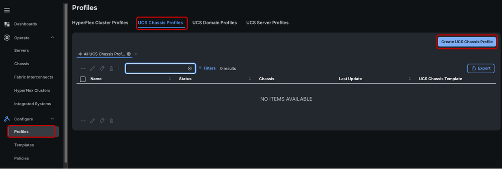
Under the Configure section in the navigation pane, click Profiles.
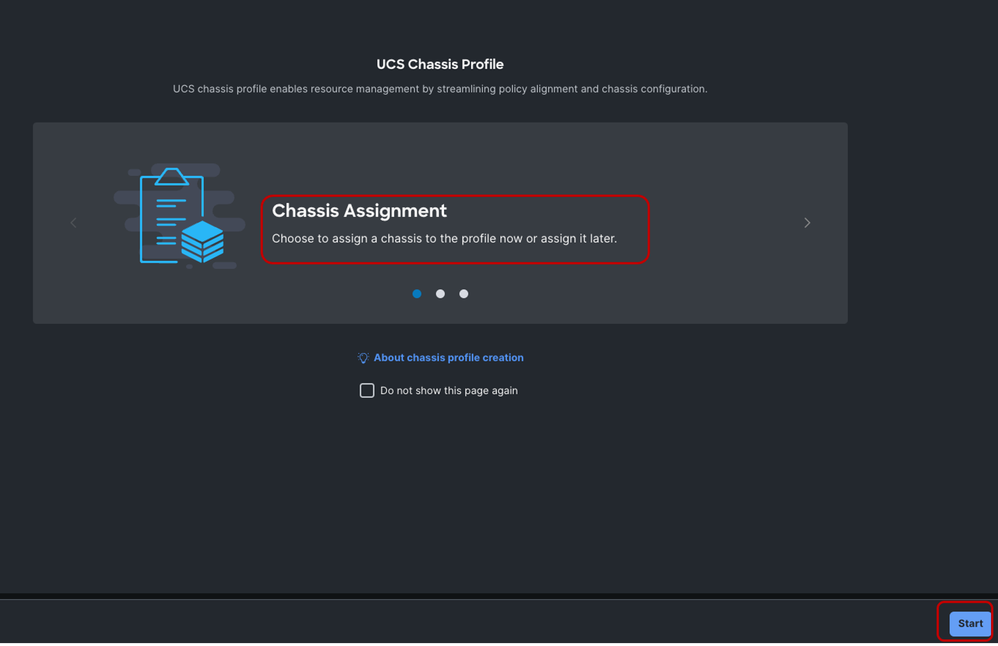
Select the UCS Chassis Profiles tab. Click Create UCS Chassis Profile.
In the Chassis Assignment page, click Start.
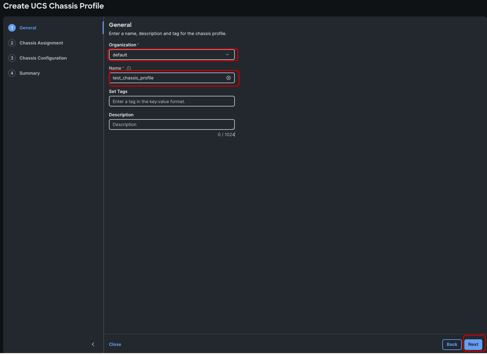
Choose your desired Organization, name the Chassis Profile and click Next.
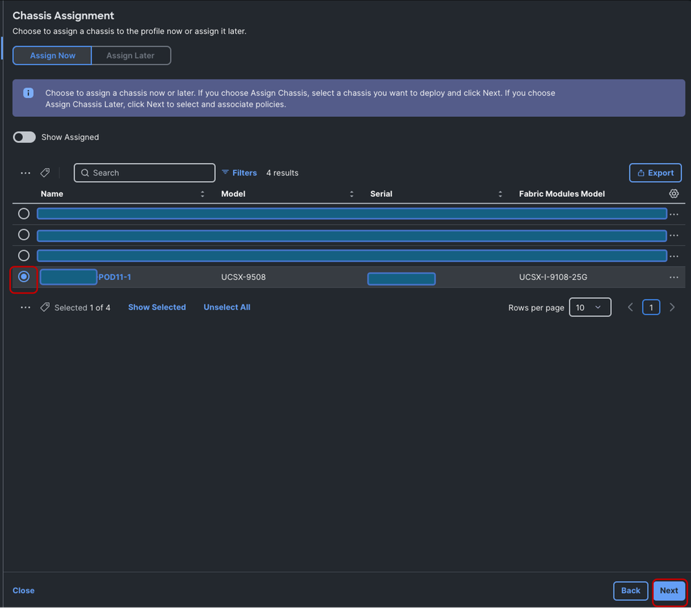
Select the appropriate chassis to assign the Chassis Profile and click Next.
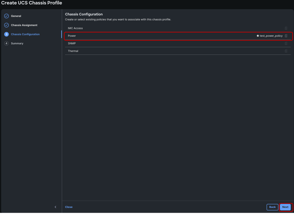
In the Create UCS Chassis Profile window, hover over the extreme right end of the Power option and click Select Policy.
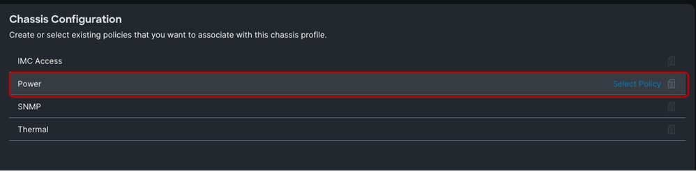
In the pop-up list, search for the earlier created power policy and select it.
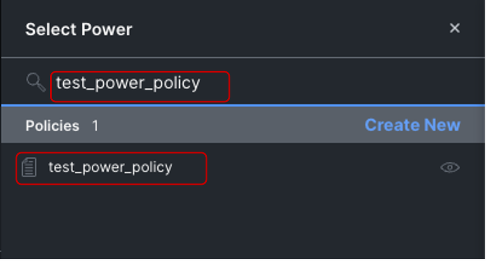
Then click Next
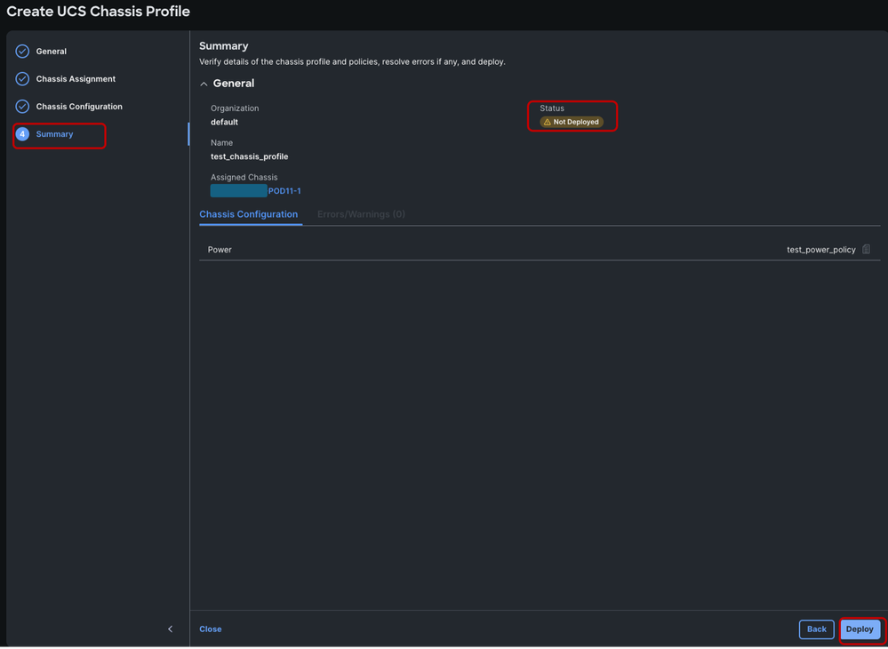
On the summary page, click Deploy.
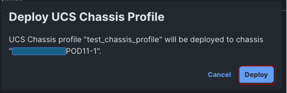
Confirm the deployment by selecting Deploy.
This activity is completed within a couple of minutes, and it is not service impacting.
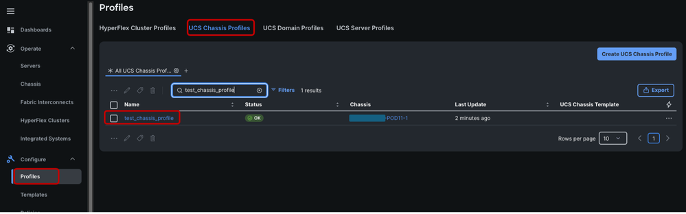
The Chassis Profile with Power Policy has been successfully configured on UCS X9508 Chassis.
Helpful links:
 Feedback