Introduction
This document describes how to configure Dual Internet Service Provider (ISP) failover using Firewall Device Manager (FDM) for Secure Firewall Series.
Prerequisites
Requirements
Cisco recommends that you have knowledge of these topics:
Components Used
The information in this document is based on these software and hardware versions:
• Cisco Secure Firewall running 7.7.X version or higher versions.
• Secure Firewall 3130 with 7.7.0 version.
The information in this document was created from the devices in a specific lab environment. All of the devices used in this document started with a cleared (default) configuration. If your network is live, ensure that you understand the potential impact of any command.
Configure
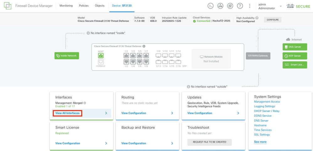
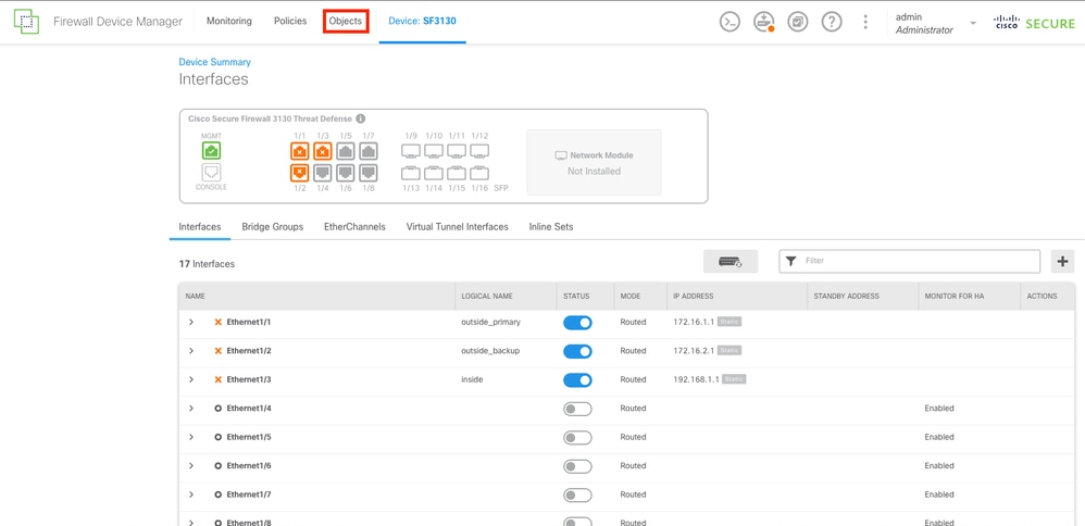
Step 1.
Log in to the FDM on the Secure Firewall, and navigate to the interfaces section by selecting the View All Interfaces button.
 FDM Main Dashboard
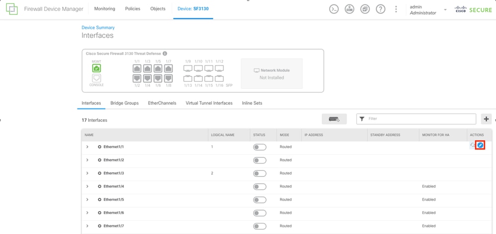
Step 2.
To configure the interface for the Primary ISP connection, start by selecting your desired interface. Selecting the corresponding interface button to proceed. In this example, the interface used is Ethernet1/1.
 Interfaces Tab
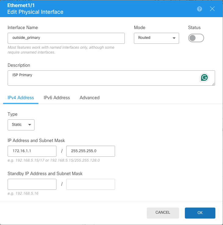
Step 3.
Configure the interface with the correct parameters for your Primary ISP connection. In this example, the interface is outside_primary.
 Configuration of primary ISP interface
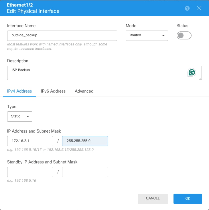
Step 4.
Repeat the same process for the secondary ISP interface. In this example, the interface Ethernet1/2 is used.
 Configuration of secondary ISP interface
Step 5.
After configuring the two interfaces for the ISPs, the next step is to set up the SLA Monitor for the primary interface.
Navigate to the Objects section by selecting the Objects button located at the top of the menu.
 Configured Interfaces
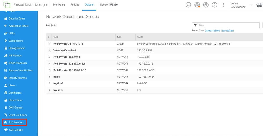
Step 6.
Select on the left column, the SLA Monitors button.
 Objects Screen
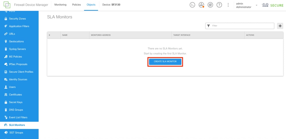
Step 7.
Create a new SLA Monitor by selecting the Create SLA Monitor button.
 SLA Monitor Section
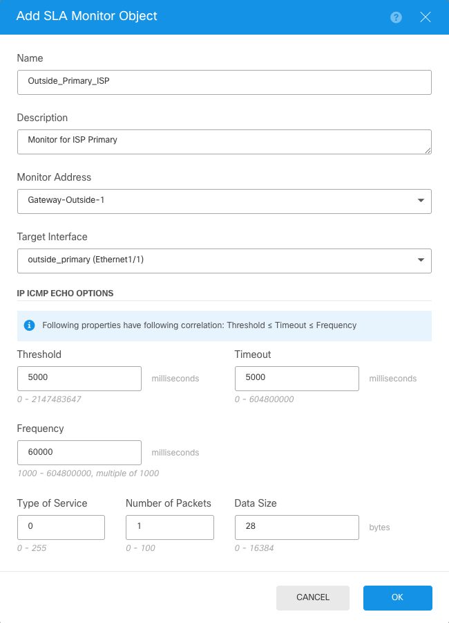
Step 8.
Configure the parameters for the Primary ISP connection.
 SLA Object Creation
Step 9.
Once the object was created, the static route for the interfaces must create it. Navigate to the main dashboard by selecting the Device button.
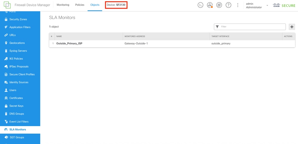 SLA Monitor Created
Step 10.
Navigate to the Routing Section by selecting the View Configuration in the Routing Panel.
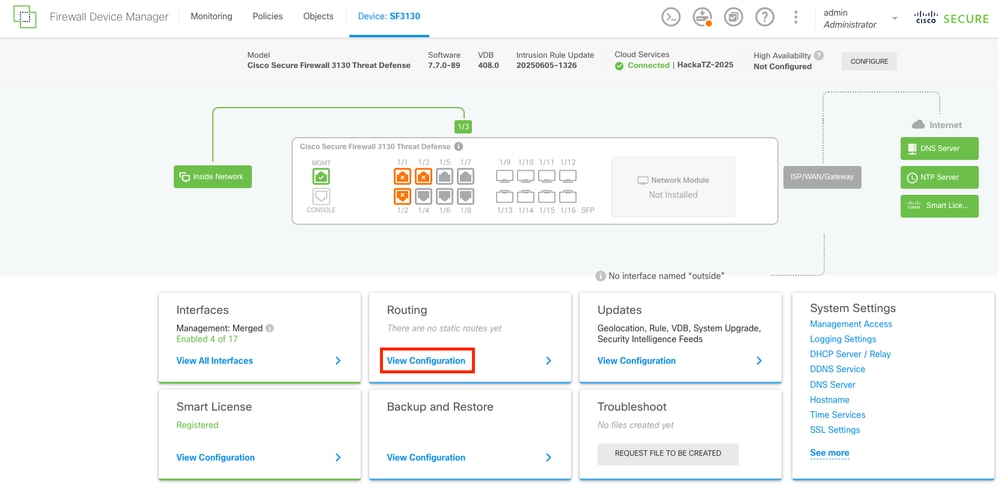 Main Dashboard
Step 11.
On the Static Routing tab, create the 2 default static routes for both ISPs. To create a new Static Route select the CREATE STATIC ROUTE button.
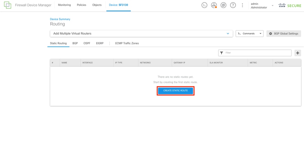 Static Routing Section
Step 12.
First, create the Static Route for the Primary ISP. At the end, add the SLA monitor object that was created on last step.
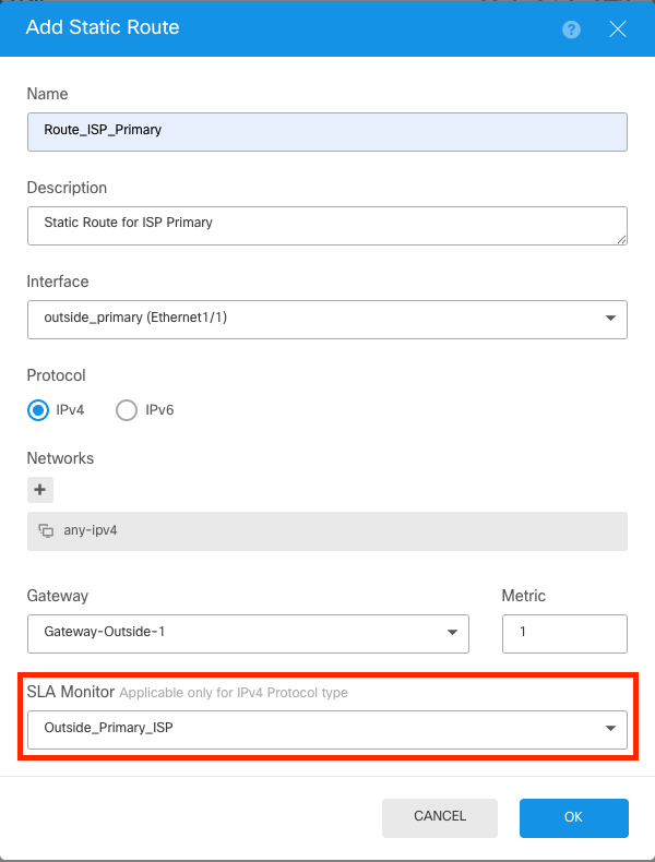 Static Route For Primary ISP
Step 13.
Repeat the last step and create a default route, for the ISP secondary with the proper gateway and different Metric. In this example, it was increased to 200.
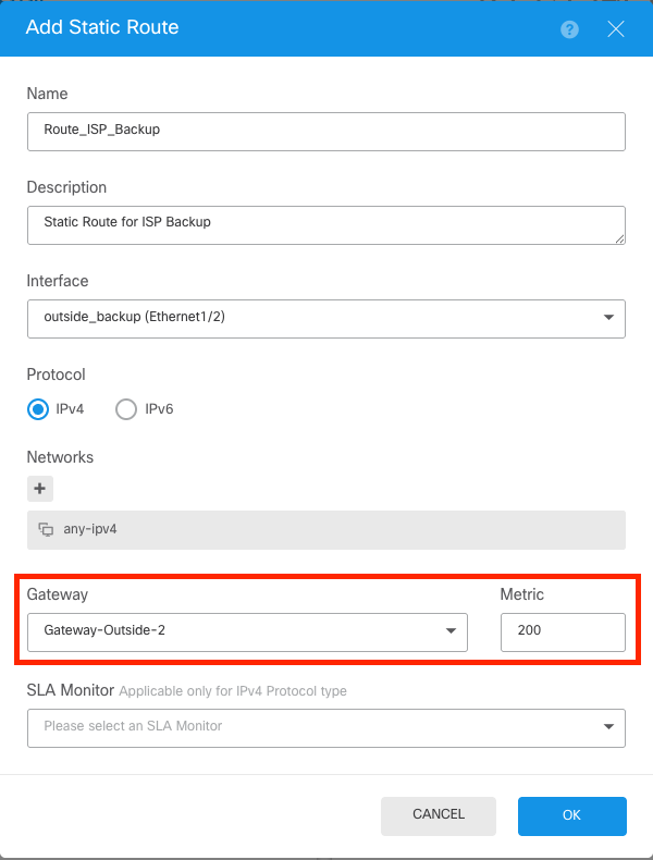 Static Route For Secondary ISP
Step 14.
Once both static routes are created, a Security Zone must be created. Navigate to the Objects section by selecting the Objects button on the top.
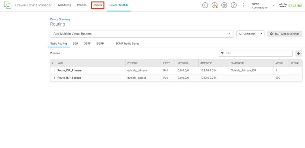 Static Routes Created
Step 15.
Navigate to the Security Zones section by selecting on the left column the Security Zones button, and then create a new zone by selecting the CREATE SECURITY ZONE button.
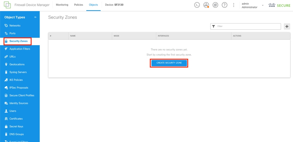 Security Zones Section
Step 16.
Create the Outside Security Zone with the both outside interfaces for the ISPs connections.
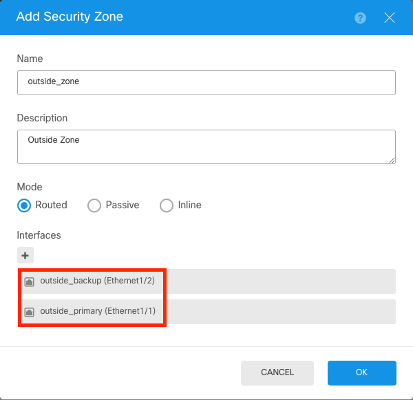 Security Zone Outside
Step 17.
After the security zone is created, a NAT must be created. Navigate to Policies section by selecting the Policies button on the top.
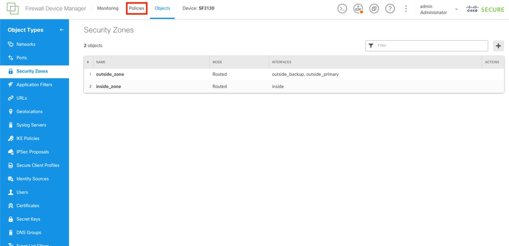 Security Zones Created
Step 18.
Navigate to the NAT section by selecting the NAT button, and then create a new rule by selecting the CREATE NAT RULE button.
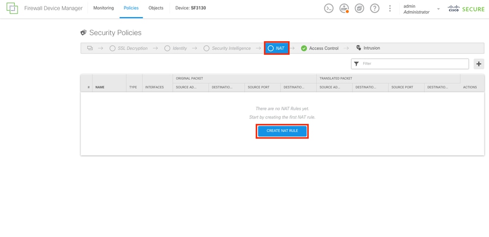 NAT Section
Step 19.
For the ISP failover, the configuration must have 2 routes via outside interfaces. First, for the Primary Outside interface connection to the Primary ISP.
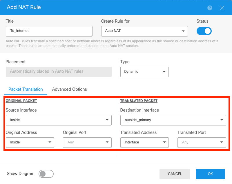 NAT For Primary ISP
Step 20.
Now, a second NAT for the Secondary ISP connection.
Note: For the original address, same network cannot be used. In this example, for the secondary ISP, the Original Address is the object any-ipv4.
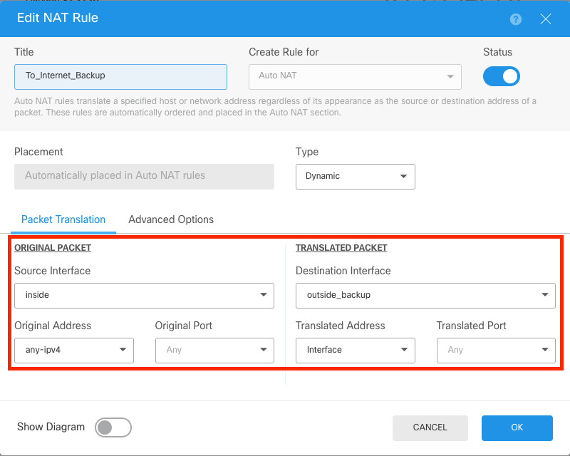 NAT For Secondary ISP
Step 21.
After creating both NAT rules, an Access Control Rule must be established to allow outbound traffic. Select the Access Control button.
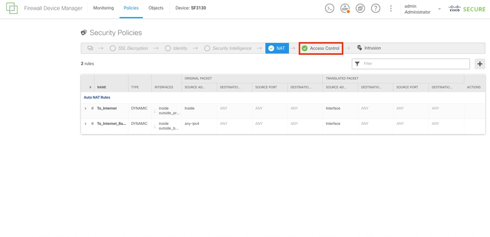 NAT Rules Created
Step 22.
To create the Access Control Rule, select the CREATE ACCESS RULE button.
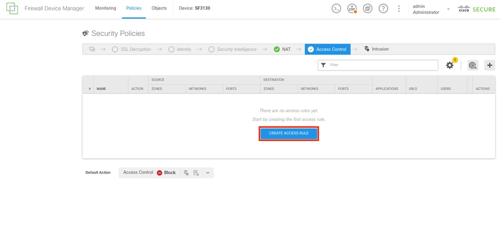 Access Control Section
Step 23.
Select the zones and networks desired.
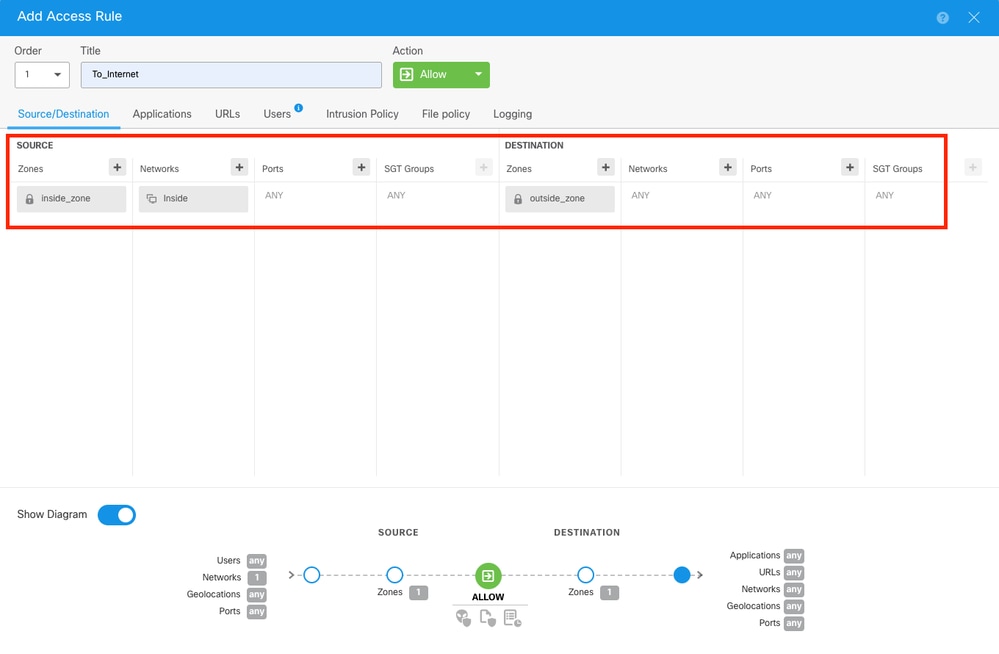 Access Control Rule
Step 24.
Once the Access Control Rule is created, proceed to deploy all changes by selecting the Deploy button on the top.
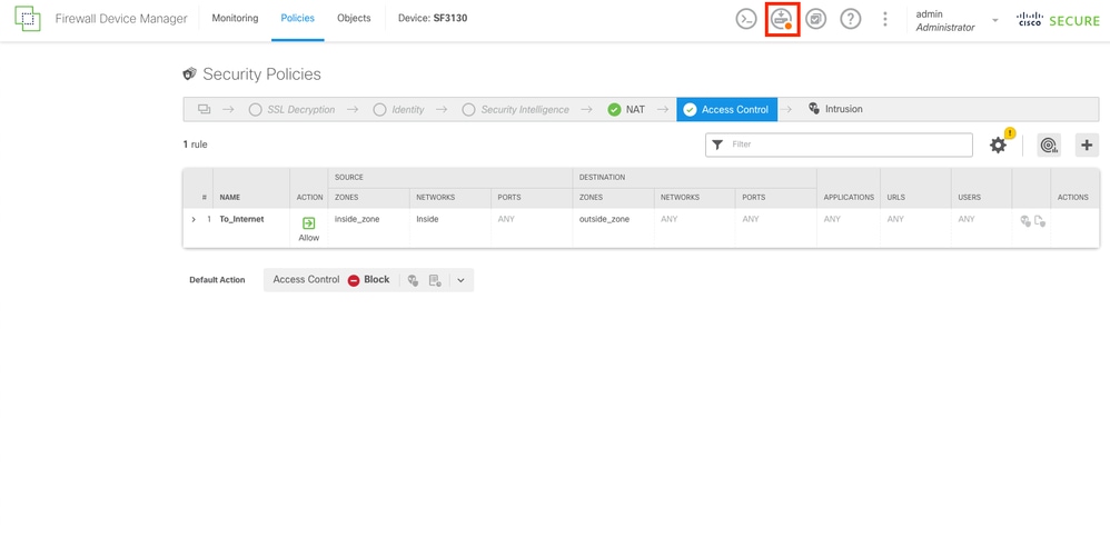 Access Control Rule Created
Step 25.
Verify the changes and then select the Deploy Now button.
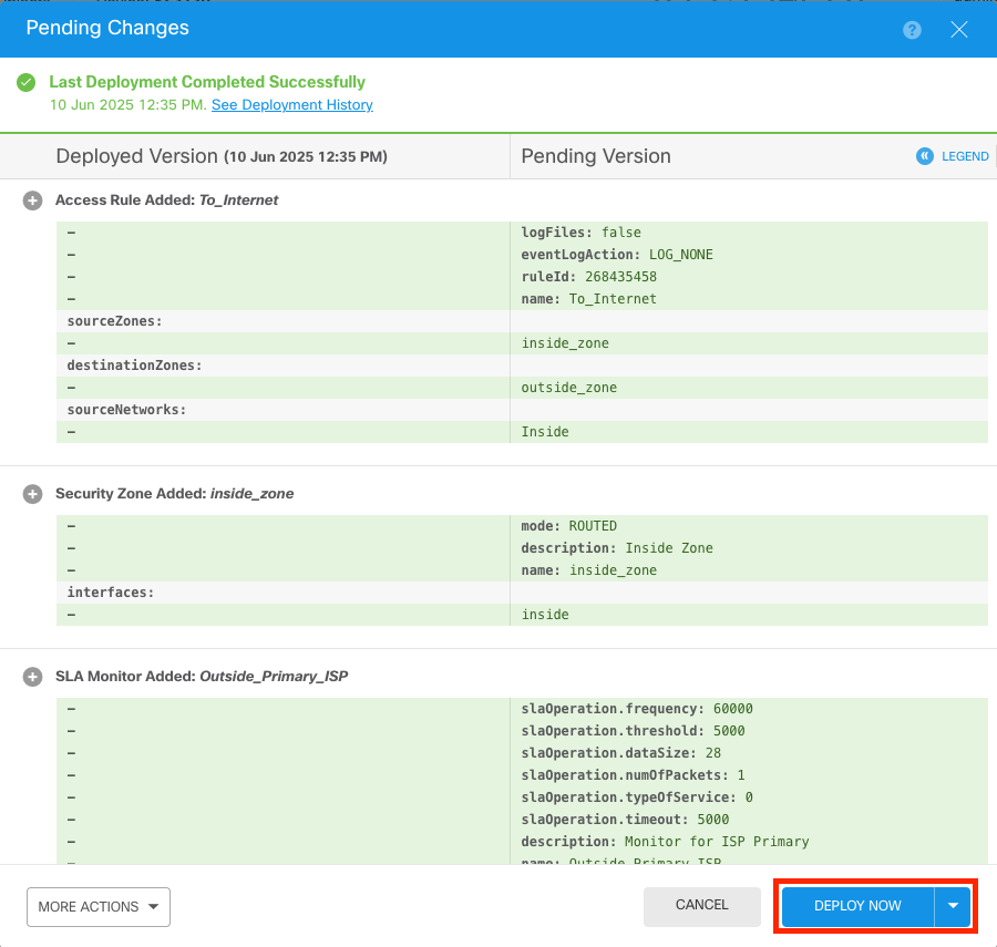 Deployment Verification
Network Diagram
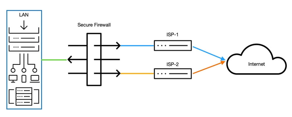 Network Diagram
Verify
> system support diagnostic-cli
Attaching to Diagnostic CLI ... Press 'Ctrl+a then d' to detach.
Type help or '?' for a list of available commands.

SF3130# show ip
System IP Addresses:
Interface   Name            IP address  Subnet mask   Method
Ethernet1/1 outside_primary 172.16.1.1  255.255.255.0 manual ------------> THE PRIMARY INTERFACE OF THE ISP IS SET
Ethernet1/2 outside_backup  172.16.2.1  255.255.255.0 manual ------------> THE SECONDARY INTERFACE OF THE ISP IS SET
Ethernet1/3 inside          192.168.1.1 255.255.255.0 manual

SF3130# show interface ip brief
Interface   IP-Address  OK? Method Status Protocol
Ethernet1/1 172.16.1.1  YES manual   up      up -------------------> THE INTERFACE IS UP AND RUNNING
Ethernet1/2 172.16.2.1  YES manual   up      up -------------------> THE INTERFACE IS UP AND RUNNING
Ethernet1/3 192.168.1.1 YES manual   up      up

SF3130# show route
Gateway of last resort is 172.16.1.254 to network 0.0.0.0

S* 0.0.0.0 0.0.0.0 [1/0] via 172.16.1.254, outside_primary ----> THE DEFAULT ROUTE IS CONNECTED THROUGH THE PRIMARY ISP
C  172.16.1.0  255.255.255.0   is directly connected, outside_primary
L  172.16.1.1  255.255.255.255 is directly connected, outside_primary
C  172.16.2.0  255.255.255.0   is directly connected, outside_backup
L  172.16.2.1  255.255.255.255 is directly connected, outside_backup
C  192.168.1.0 255.255.255.0   is directly connected, inside
L  192.168.1.1 255.255.255.255 is directly connected, inside

SF3130# show run route
route outside_primary 0.0.0.0 0.0.0.0 172.16.1.254 1 track 1
route outside_backup  0.0.0.0 0.0.0.0 172.16.2.254 200

SF3130# show sla monitor configuration ---> CHECKING THE SLA MONITOR CONFIGURATION
SA Agent, Infrastructure Engine-II
Entry number: 539523651
Owner:
Tag:
Type of operation to perform: echo
Target address: 172.16.1.254
Interface: outside_primary
Number of packets: 1
Request size (ARR data portion): 28
Operation timeout (milliseconds): 3000
Type Of Service parameters: 0x0
Verify data: No
Operation frequency (seconds): 3
Next Scheduled Start Time: Start Time already passed
Group Scheduled : FALSE
Life (seconds): Forever
Entry Ageout (seconds): never
Recurring (Starting Everyday): FALSE
Status of entry (SNMP RowStatus): Active
Enhanced History:

SF3130# show sla monitor operational-state
Entry number: 739848060
Modification time: 01:24:11.029 UTC Thu Jun 12 2025
Number of Octets Used by this Entry: 1840
Number of operations attempted: 0
Number of operations skipped: 0
Current seconds left in Life: Forever
Operational state of entry: Pending
Last time this entry was reset: Never
Connection loss occurred: FALSE
Timeout occurred: FALSE ----------------------------> THE ISP PRIMARY IS IN A HEALTHY STATE
Over thresholds occurred: FALSE
Latest RTT (milliseconds) : Unknown
Latest operation return code: Unknown
Latest operation start time: Unknown

AFTERARGBSETHBNDGFSHNDFGSDBFB

SF3130# show interface ip brief
Interface   IP-Address  OK? Method Status Protocol
Ethernet1/1 172.16.1.1  YES manual  down   down -------------------> THE PRIMARY ISP IS DOWN
Ethernet1/2 172.16.2.1  YES manual   up     up
Ethernet1/3 192.168.1.1 YES manual   up     up

SF3130# show route
Gateway of last resort is 172.16.2.254 to network 0.0.0.0

S* 0.0.0.0 0.0.0.0 [200/0] via 172.16.2.254, outside_backup ---------> AFTER THE ISP PRIMARY FAILS, INSTANTLY THE ISP BACKUP IS FAILOVER AND IS INSTALL IN THE ROUTING TABLE
C  172.16.2.0 255.255.255.0    is directly connected, outside_backup
L  172.16.2.1 255.255.255.255  is directly connected, outside_backup
C  192.168.1.0 255.255.255.0   is directly connected, inside
L  192.168.1.1 255.255.255.255 is directly connected, inside

SF3130# show sla monitor operational-state
Entry number: 739848060
Modification time: 01:24:11.140 UTC Thu Jun 12 2025
Number of Octets Used by this Entry: 1840
Number of operations attempted: 0
Number of operations skipped: 0
Current seconds left in Life: Forever
Operational state of entry: Pending
Last time this entry was reset: Never
Connection loss occurred: FALSE
Timeout occurred: TRUE -------------------------------------> AFTER THE DOWNTIME OF THE PRIMARY ISP THE TIMEOUT IS FLAGGED
Over thresholds occurred: FALSE
Latest RTT (milliseconds) : Unknown
Latest operation return code: Unknown
Latest operation start time: Unknown

SF3130# show route
Gateway of last resort is 172.16.1.254 to network 0.0.0.0

S* 0.0.0.0 0.0.0.0 [1/0] via 172.16.1.254, outside_primary ------------> AFTER A FEW SECONDS ONCE THE PRIMARY INTERFACE IS BACK THE DEFAULT ROUTE INSTALLS AGAIN IN THE ROUTING TABLE
C 172.16.1.0 255.255.255.0    is directly connected, outside_primary
L 172.16.1.1 255.255.255.255  is directly connected, outside_primary
C 172.16.2.0 255.255.255.0    is directly connected, outside_backup
L 172.16.2.1 255.255.255.255  is directly connected, outside_backup
C 192.168.1.0 255.255.255.0   is directly connected, inside
L 192.168.1.1 255.255.255.255 is directly connected, inside
 Feedback