Configure Dual Active Route-Based Site-to-Site VPN with PBR on FTD Managed by FDM
Available Languages
Download Options
Bias-Free Language
The documentation set for this product strives to use bias-free language. For the purposes of this documentation set, bias-free is defined as language that does not imply discrimination based on age, disability, gender, racial identity, ethnic identity, sexual orientation, socioeconomic status, and intersectionality. Exceptions may be present in the documentation due to language that is hardcoded in the user interfaces of the product software, language used based on RFP documentation, or language that is used by a referenced third-party product. Learn more about how Cisco is using Inclusive Language.
Contents
Introduction
This document describes how to configure dual active route-based site-to-site VPN with PBR on FTD managed by FDM.
Prerequisites
Requirements
Cisco recommends that you have knowledge of these topics:
- Basic understanding of VPN
- Basic understanding of Policy Based Routing (PBR)
- Basic understanding of Internet Protocol Service Level Agreement (IP SLA)
- Experience with FDM
Components Used
The information in this document is based on these software and hardware versions:
- Cisco FTDv version 7.4.2
- Cisco FDM version 7.4.2
The information in this document was created from the devices in a specific lab environment. All of the devices used in this document started with a cleared (default) configuration. If your network is live, ensure that you understand the potential impact of any command.
Background Information
This document explains how to configure a dual active route-based site-to-site VPN on FTD. In this example, FTDs at both Site1 and Site2 have dual active ISP connections establishing the site-to-site VPN with both ISPs simultaneously. By default, VPN traffic traverses Tunnel 1 over ISP1 (blue line). For specific hosts, traffic goes through Tunnel 2 over ISP2 (red line). If ISP1 experiences an interruption, traffic switches to ISP2 as a backup. Conversely, if ISP2 experiences an interruption, traffic switches to ISP1 as a backup. Policy-Based Routing (PBR) and Internet Protocol Service Level Agreement (IP SLA) are utilized in this example to meet these requirements.
Configure
Network Diagram
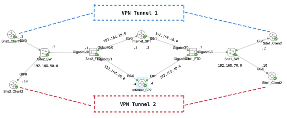 Topology
Configurations on VPN
It is essential to ensure that the preliminary configuration of IP interconnectivity between nodes has been duly completed. The clients in both Site1 and Site2 are with FTD inside IP address as gateway.
Site1 FTD VPN Configuration
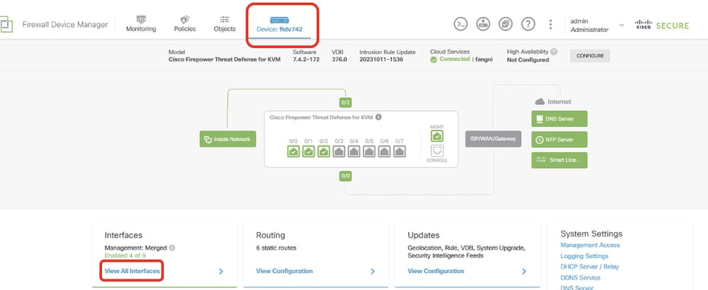
Step 1. Create virtual tunnel interfaces for ISP1 and ISP2. Login the FDM GUI of Site1 FTD. Navigate to Device > Interfaces. Click View All Interfaces.
 Site1FTD_View_All_Interfaces
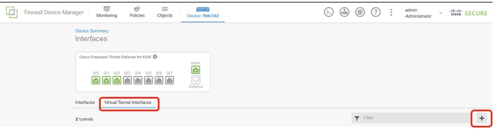
Step 2. Click Virtual Tunnel Interfaces tab and then the + button.
 Site1FTD_Create_VTI
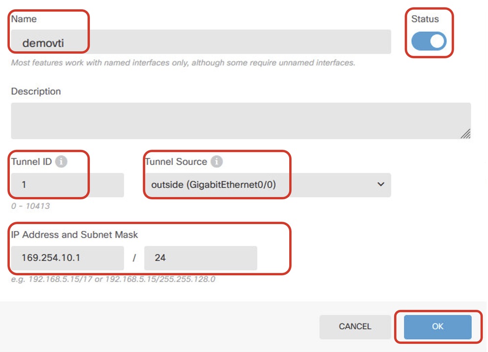
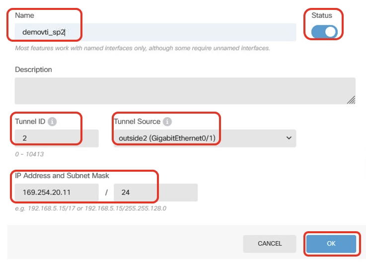
Step 3. Provide necessary information of VTI details. Click OK button.
- Name: demovti
- Tunnel ID: 1
- Tunnel Source: outside (GigabitEthernet0/0)
- IP Address And Subnet Mask: 169.254.10.1/24
- Status: click the slider to the Enabled position
 Site1FTD_VTI_Details_Tunnel1_ISP1
- Name: demovti_sp2
- Tunnel ID: 2
- Tunnel Source: outside2 (GigabitEthernet0/1)
- IP Address And Subnet Mask: 169.254.20.11/24
- Status: click the slider to the Enabled position
 Site1FTD_VTI_Details_Tunnel2_ISP2
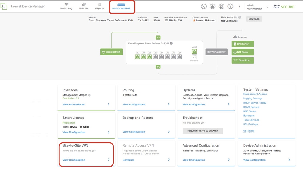
Step 4. Navigate to Device > Site-to-Site VPN. Click View Configuration button.
 Site1FTD_View_Site2Site_VPN
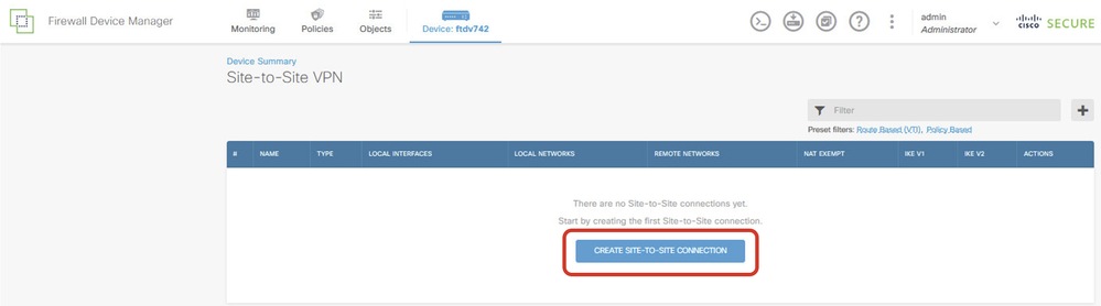
Step 5. Start to create new site-to-site VPN through ISP1. Click CREATE SITE-TO-SITE CONNECTION button, or click the + button.
 Site1FTD_Create_Site-to-Site_Connection
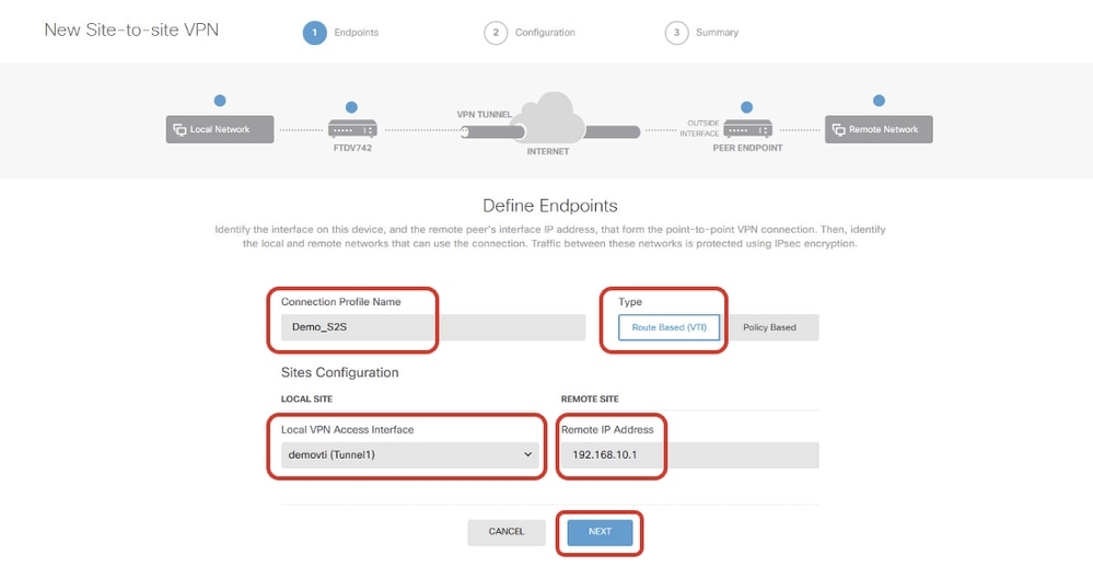
Step 5.1. Provide necessary information of Endpoints. Click NEXT button.
- Connection Profile Name: Demo_S2S
- Type: Route Based (VTI)
- Local VPN Access Interface: demovti (created in Step 3.)
- Remote IP Address: 192.168.10.1 (this is Site2 FTD ISP1 IP address)
 Site1FTD_ISP1_Site-to-Site_VPN_Define_Endpoints
Step 5.2. Navigate to IKE Policy. Click EDIT button.
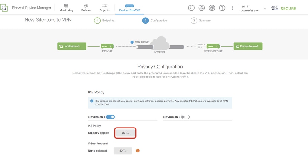 Site1FTD_Edit_IKE_Policy
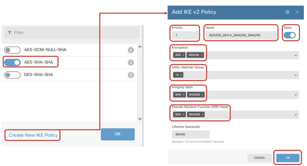
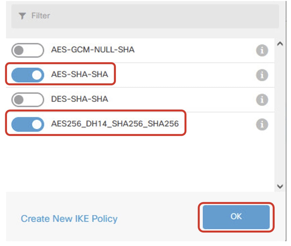
Step 5.3. For IKE policy, you can use pre-defined or you can create a new one by clicking Create New IKE Policy.
In this example, toggle an existing IKE policy AES-SHA-SHA and also create a new one for demo purpose. Click OK button in order to save.
- Name: AES256_DH14_SHA256_SHA256
- Encryption: AES, AES256
- DH Group: 14
- Integrity Hash: SHA, SHA256
- PRF Hash: SHA, SHA256
- Lifetime: 86400 (default)
 Site1FTD_Add_New_IKE_Policy
 Site1FTD_Enable_New_IKE_Policy
Step 5.4. Navigate to IPSec Proposal. Click EDIT button.
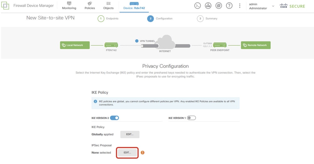 Site1FTD_Edit_IKE_Proposal
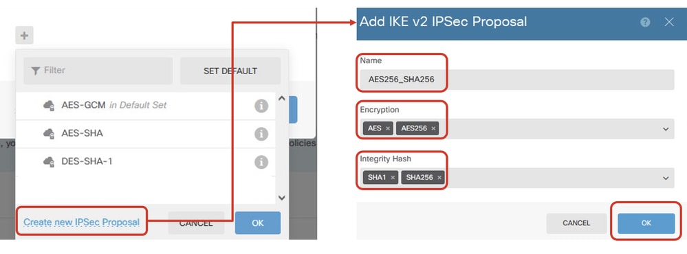
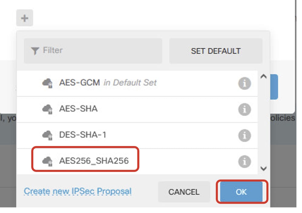
Step 5.5. For IPSec proposal, you can use pre-defined or you can create a new one by clicking Create new IPSec Proposal. In this example, create a new one for demo purpose. Click OK button in order to save.
- Name: AES256_SHA256
- Encryption: AES, AES256
- Integrity Hash: SHA1, SHA256
 Site1FTD_Add_New_IKE_Proposal
 Site1FTD_Enable_New_IKE_Proposal
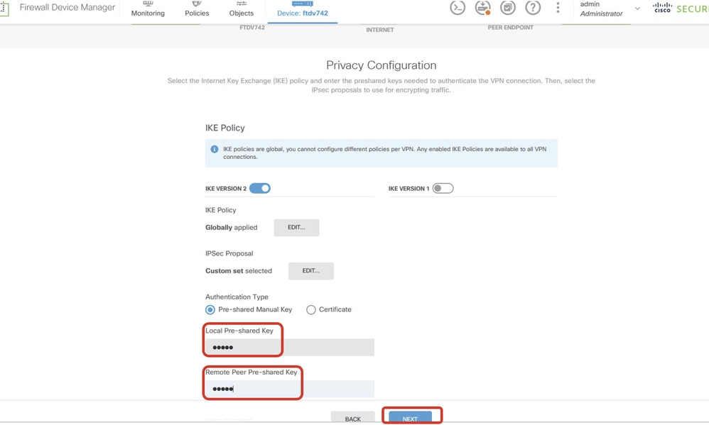
Step 5.6. Scroll down the page and configure the pre-shared key. ClickNEXTbutton.
Note down this pre-shared key and configure it on Site2 FTD later.
 Site1FTD_Configure_Pre_Shared_Key
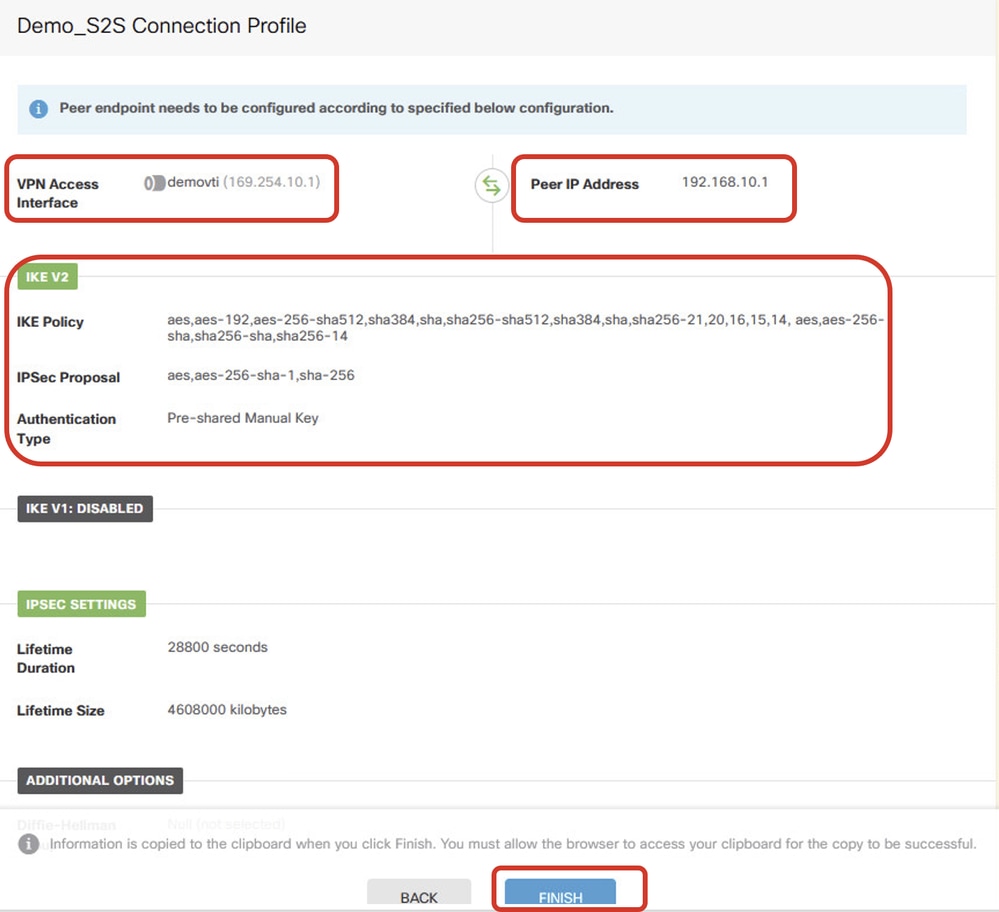
Step 5.7. Review the VPN configuration. If anything needs to be modified, click the BACK button. If everything is good, click the FINISH button.
 Site1FTD_ISP1_Review_VPN_Config_Summary
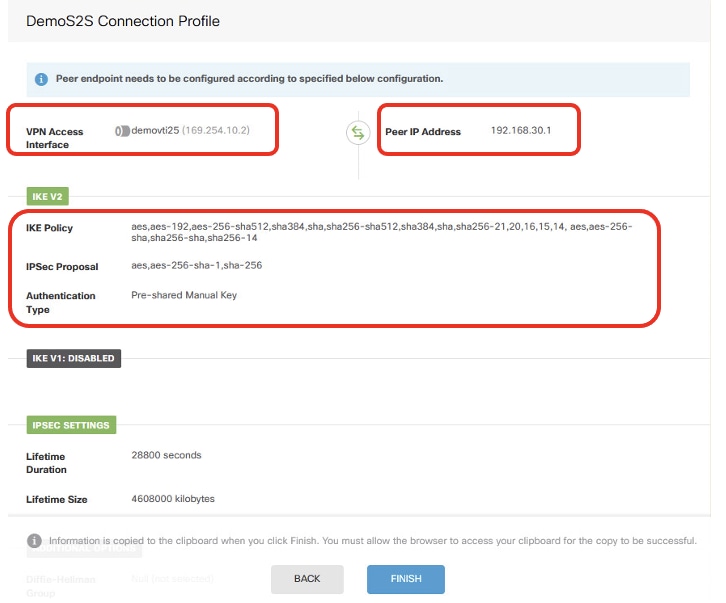
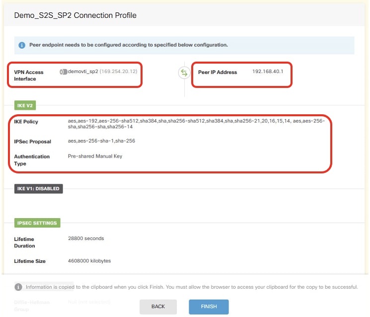
Step 6. Repeat the Step 5. in order to create new site-to-site VPN through ISP2.
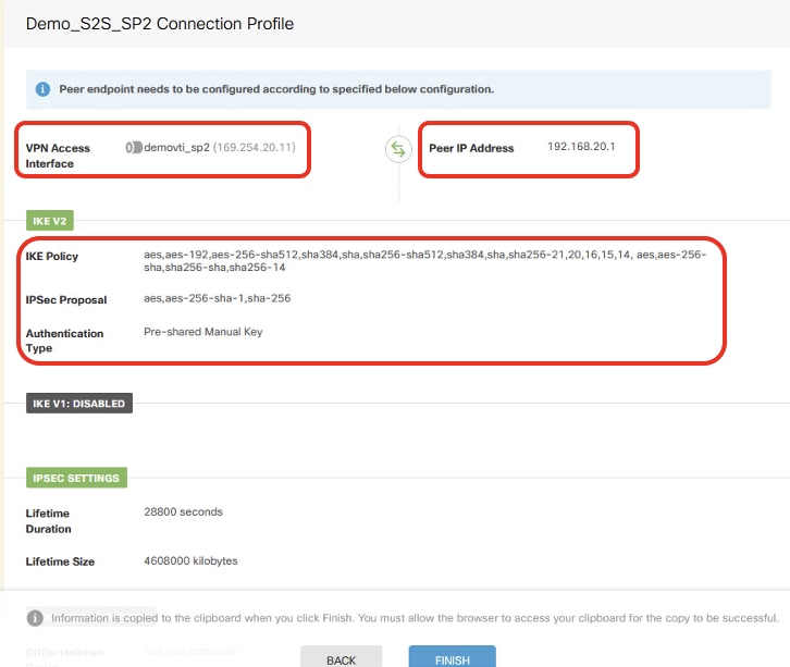 Site1FTD_ISP2_Review_VPN_Config_Summary
Step 7. Create Access Control rule in order to allow traffic pass through the FTD. In this example, allow all for demo purpose. Modify your policy based on your actual needs.
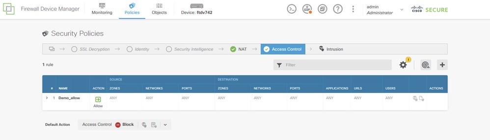 Site1FTD_Allow_Access_Control_Rule_Example
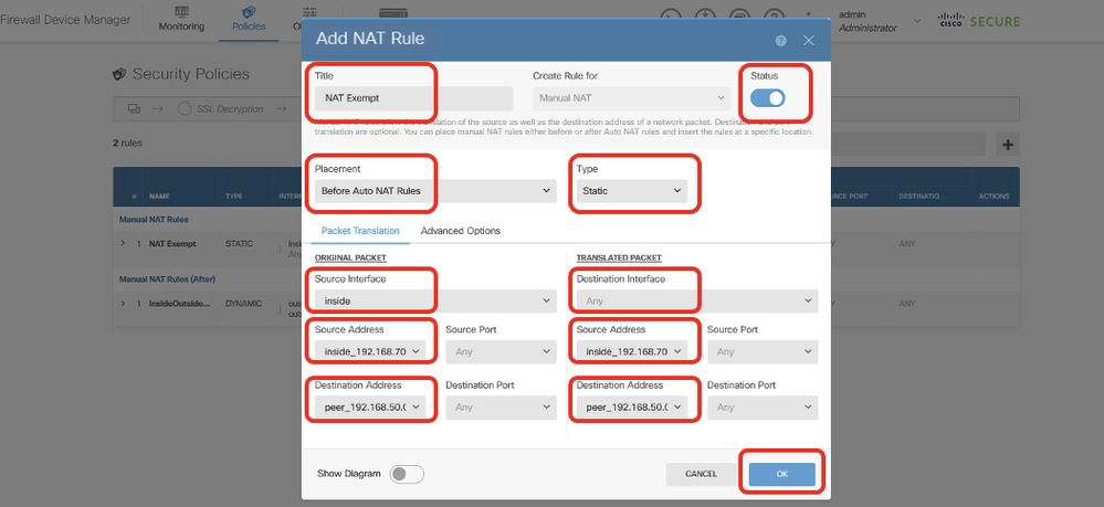
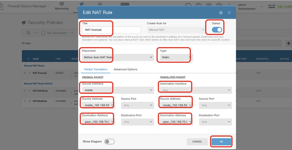
Step 8. (Optional) Configure NAT exempt rule for the client traffic on FTD if there is dynamic NAT configured for client in order to access internet.
For demo purpose, dynamic NAT is configured for clients in order to access internet in this example. Therefore NAT exempt rule is needed.
Navigate to Policies > NAT. Click + button. Provide the details and click OK.
- Title: NAT Exempt
- Placement: Before Auto NAT Rules
- Type: Static
- Source Interface: Inside
- Destination: Any
- Original Source Address: 192.168.70.0/24
- Translated Source Address: 192.168.70.0/24
- Original Destination Address: 192.168.50.0/24
- Translated Destination Address: 192.168.50.0/24
- With Route-Lookup enabled
 Site1FTD_Nat_Exempt_Rule
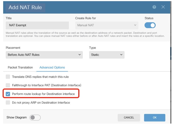 Site1FTD_Nat_Exempt_Rule_2
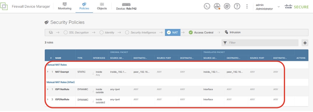 Site1FTD_Nat_Rule_Overview
Step 9. Deploy the configuration changes.
 Site1FTD_Deployment_Changes
Site2 FTD VPN Configuration
Step 10. Repeat Step 1 to Step 9 with the corresponding parameters for Site2 FTD.
 Site2FTD_ISP1_Review_VPN_Config_Summary
 Site2FTD_ISP2_Review_VPN_Config_Summary
 Site2FTD_Nat_Exempt_Rule
Configurations on PBR
Site1 FTD PBR Configuration
Step 11. Create new network objects to be used by PBR access-list for Site1 FTD. Navigate to Objects > Networks and click + button.
 Site1FTD_Create_Network_Object
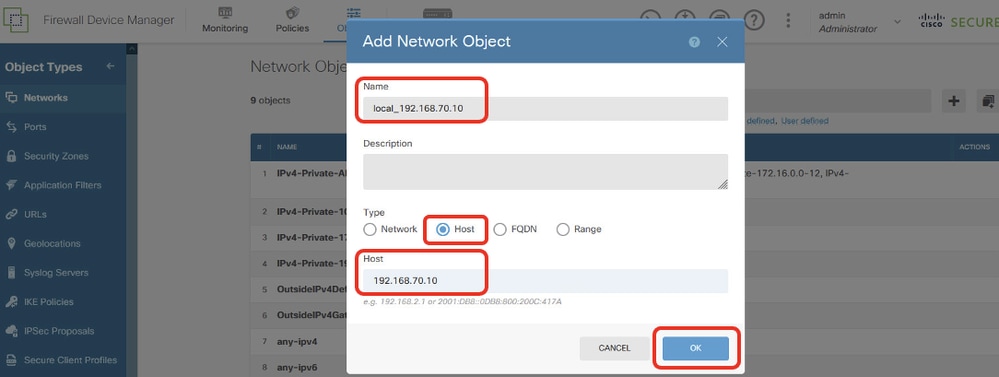
Step 11.1. Create object of Site1 Client2 IP address. Provide necessary information. Click the OK button.
- Name: local_192.168.70.10
- Type: Host
- Host: 192.168.70.10
 Site1FTD_Site1FTD_PBR_LocalObject
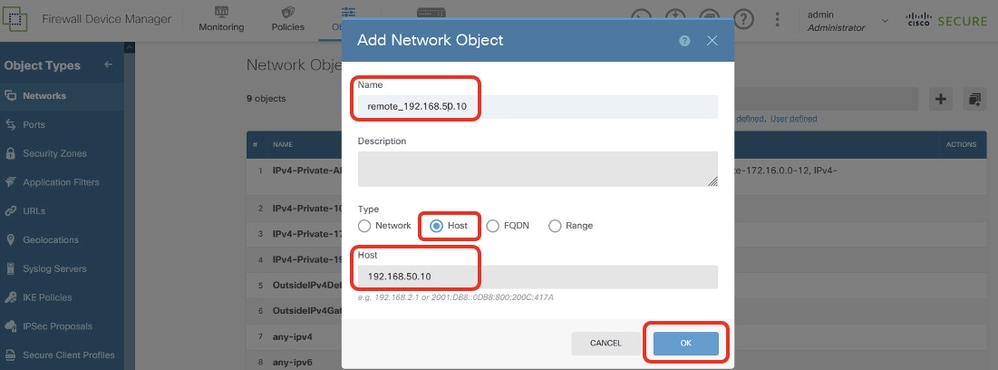
Step 11.2. Create object of Site2 Client2 IP address. Provide necessary information. Click OK button.
- Name: remote_192.168.50.10
- Type: Host
- Host: 192.168.50.10
 Site1FTD_PBR_RemoteObject
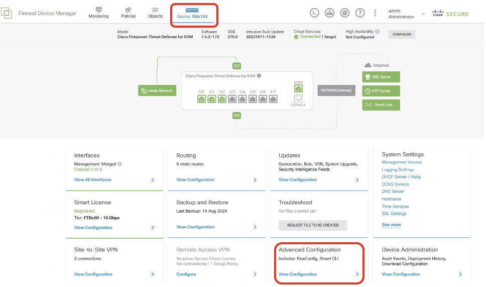
Step 12. Create extend access-list for PBR. Navigate to Device > Advanced Configuration. Click View Configuration.
 Site1FTD_View_Advanced_Configuration
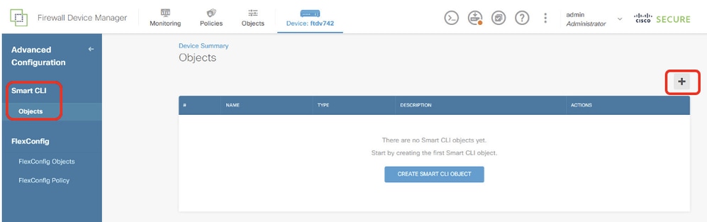
Step 12.1. Navigate to Smart CLI > Objects. Click + button.
 Site1FTD_Add_SmartCLI_Object
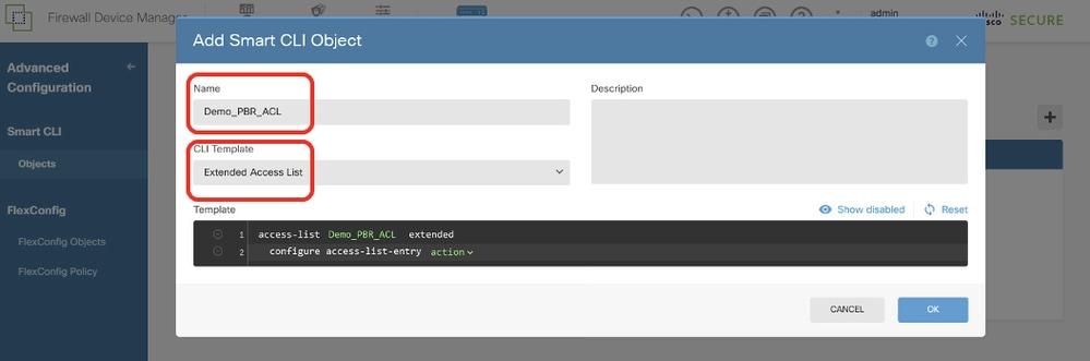
Step 12.2. Enter a name for the object and choose the CLI Template.
- Name: Demo_PBR_ACL
- CLI Template: Extended Access List
 Site1FTD_Create_PBR_ACL_1
Step 12.3. Navigate to Template and configure. Click the OK button in order to save.
Line 2, click action. Choose permit.
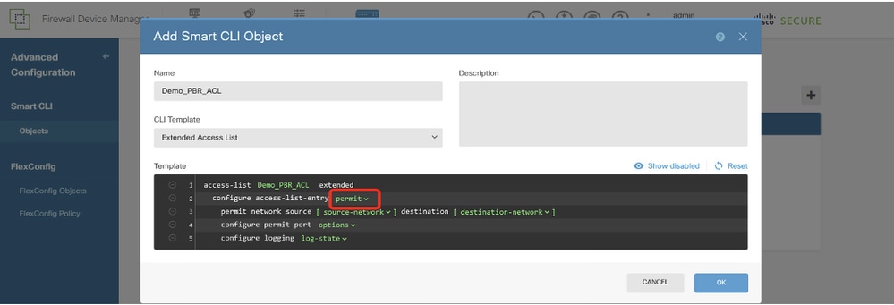 Site1FTD_Create_PBR_ACL_2
Line 3, click source-network. Choose local_192.168.70.10. Click destination-network. Choose remote_192.168.50.10.
Line 4, click options and choose any.
Line 6, click log-state and choose disabled.
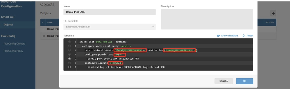 Site1FTD_Create_PBR_ACL_3
Step 13. Create route map for PBR. Navigate to Device > Advanced Configuration > Smart CLI > Objects. Click + button.
 Site1FTD_Add_SmartCLI_Object
Step 13.1. Enter a name for the object and choose the CLI Template.
- Name: Demo_PBR_RouteMap
- CLI Template: Route Map
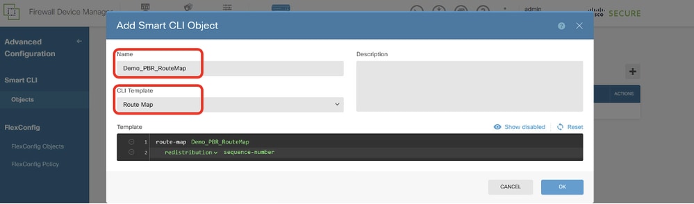 Site1FTD_Create_PBR_RouteMap_1
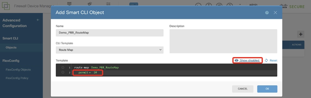
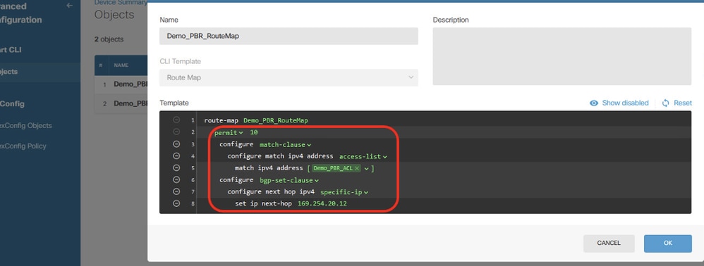
Step 13.2. Navigate to Template and configure. Click OK button to save.
Line 2, click redistribution. Choose permit. Click sequence-number, manual input 10. Click Show disabled.
 Site1FTD_Create_PBR_RouteMap_2
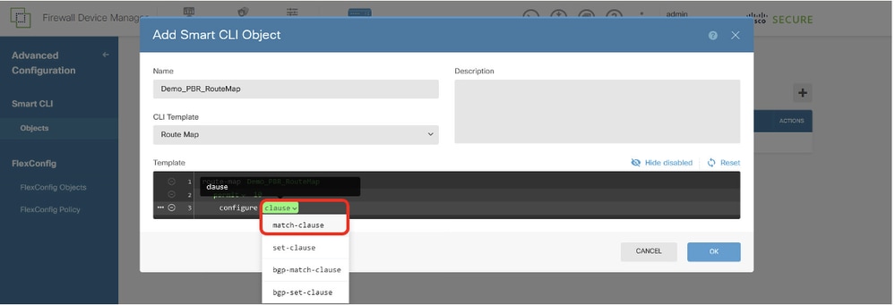
Line 3, click + to enable the line. Click clause. Choose match-clause.
 Site1FTD_Create_PBR_RouteMap_3
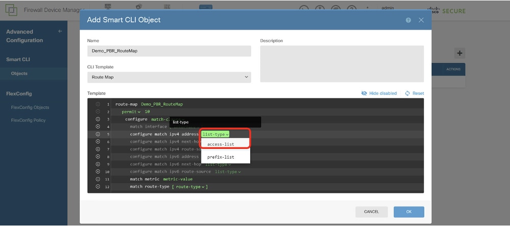
Line 4, click – to disable the line.
Line 5, click + to enable the line. Click list-type. Choose access-list.
 Site1FTD_Create_PBR_RouteMap_4
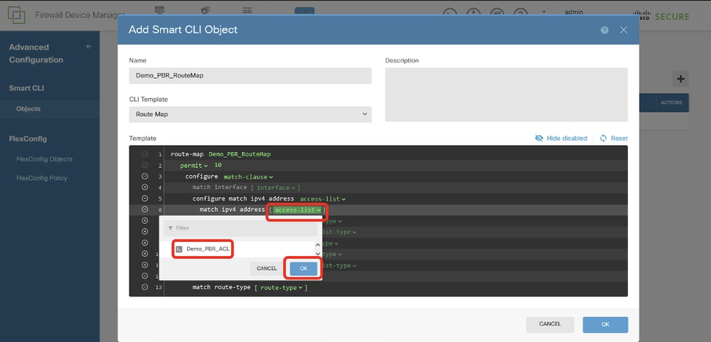
Line 6, click access-list. Choose the ACL name that is created in Step 12. In this example, it is Demo_PBR_ACL.
 Site1FTD_Create_PBR_RouteMap_5
Move back to Line 3. Click the options ... button and choose Duplicate.
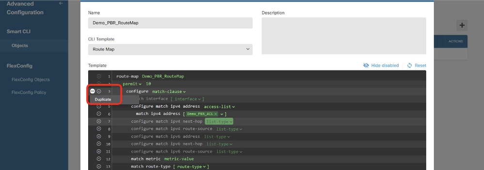 Site1FTD_Create_PBR_RouteMap_6
Line 14, click clause and choose bgp-set-clause.
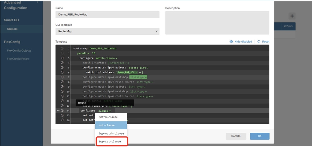 Site1FTD_Create_PBR_RouteMap_7
In Lines 12, 13, 15, 16, 17, 18, 19, 21, 22, 23, 24, click – button in order to disable.
Line 20, click options and choose specific-ip.
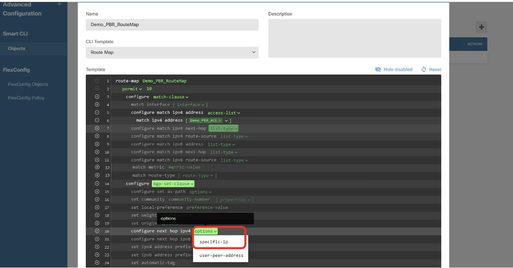 Site1FTD_Create_PBR_RouteMap_8
Line 21, click ip-address. Manual input next-hop IP address. In this example, it is IP address of peer Site2 FTD VTI tunnel2 (169.254.20.12). Click Hide disabled.
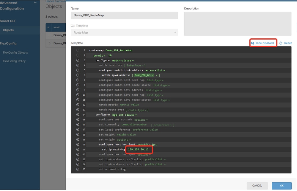 Site1FTD_Create_PBR_RouteMap_9
Review the configuration of route map.
 Site1FTD_Create_PBR_RouteMap_10
Step 14. Create FlexConfig Object for PBR. Navigate to Device > Advanced Configuration > FlexConfig Objects and click + button.
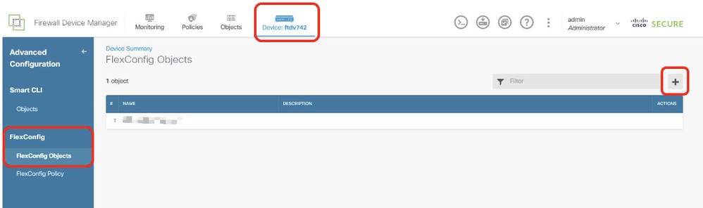 Site1FTD_Create_PBR_FlexObj_1
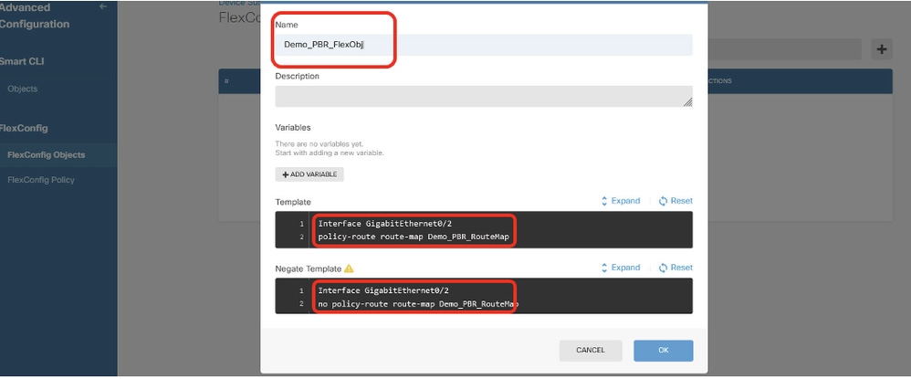
Step 14.1. Enter a name for the object. In this example, Demo_PBR_FlexObj. In the Template and Negate Template editor, enter the command lines.
- Template:
interface GigabitEthernet0/2
policy-route route-map Demo_PBR_RouteMap_Site2
- Negate Template:
interface GigabitEthernet0/2
no policy-route route-map Demo_PBR_RouteMap_Site2
 Site1FTD_Create_PBR_FlexObj_2
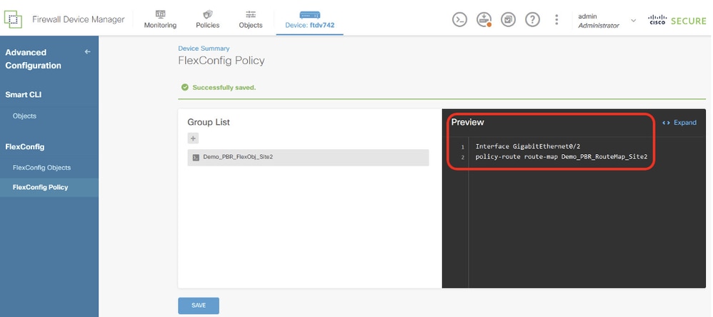
Step 15. Create FlexConfig Policy for PBR. Navigate to Device > Advanced Configuration > FlexConfig Policy. Click + button. Choose the FlexConfig Object name created in Step 14. Click OK button.
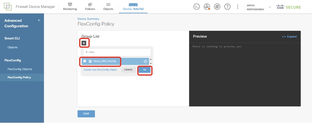 Site1FTD_Create_PBR_FlexPolicy_1
Step 15.1. Verify the command in Preview window. If it is good, click Save.
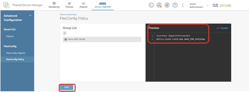 Site1FTD_Create_PBR_FlexPolicy_2
Step 16. Deploy the configuration changes.
 Site1FTD_Deployment_Changes
Site2 FTD PBR Configuration
Step 17. Repeat Step 11. to Step 16. in order to create PBR with the corresponding parameters for Site2 FTD.
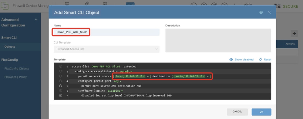 Site2FTD_Create_PBR_ACL
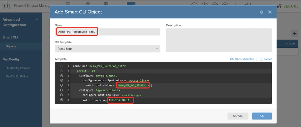 Site2FTD_Create_PBR_RouteMap
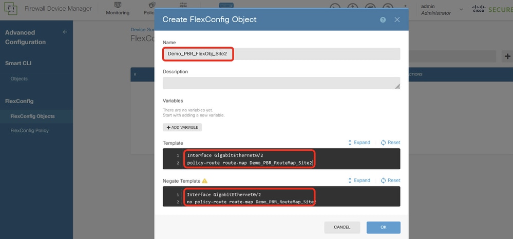 Site2FTD_Create_PBR_FlexObj
 Site2FTD_Create_PBR_FlexPolicy
Configurations on SLA Monitor
Site1 FTD SLA Monitor Configuration
Step 18. Create new network objects to be used by SLA Monitors for Site1 FTD. Navigate to Objects > Networks, click + button.
 Site1FTD_Create_Network_Object
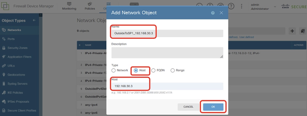
Step 18.1. Create object for ISP1 gateway IP address. Provide necessary information. Click OK button.
- Name: OutsideToSP1_192.168.30.3
- Type: Host
- Host: 192.168.30.3
 Site1FTD_Create_SLAMonitor_NetObj_ISP1
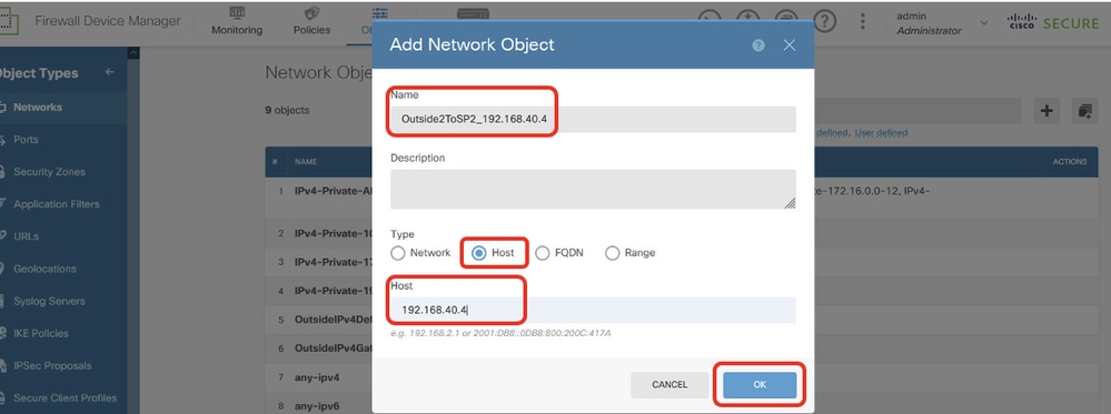
Step 18.2. Create object for ISP2 gateway IP address. Provide necessary information. Click OK button.
- Name: Outside2ToSP2_192.168.40.4
- Type: Host
- Host: 192.168.40.4
 Site1FTD_Create_SLAMonitor_NetObj_ISP2
Step 19. Create SLA Monitor. Navigate to Objects > Object Types > SLA Monitors. Click + button in order to create a new SLA monitor.
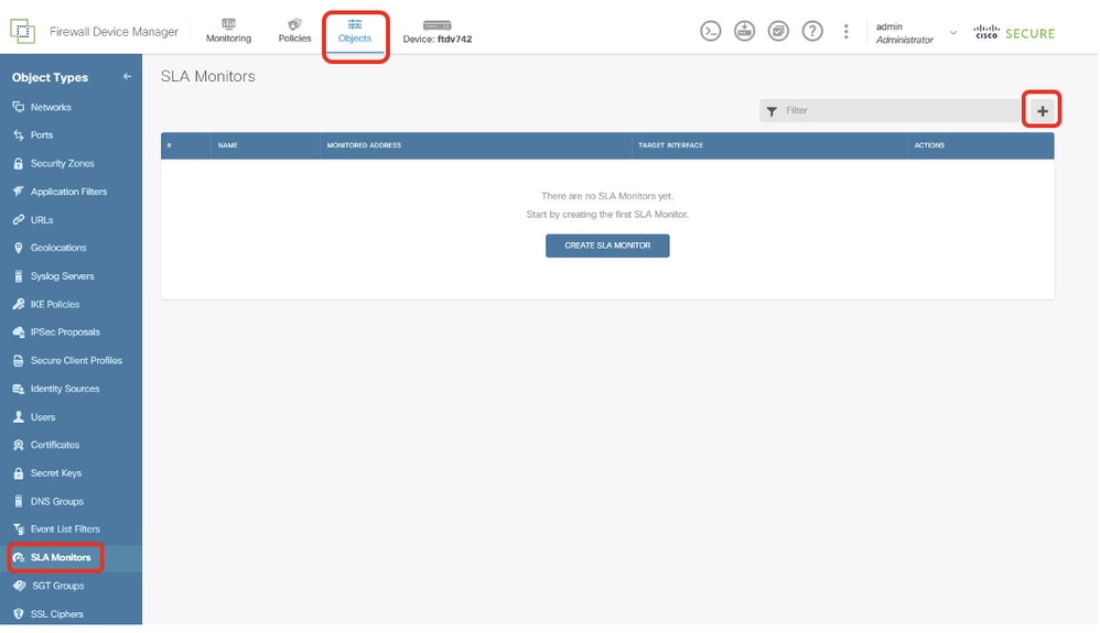 Site1FTD_Create_SLAMonitor
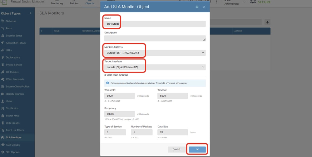
Step 19.1. In the Add SLA Monitor Object window, provide necessary information for ISP1 gateway. Click OK button to save.
- Name: sla-outside
- Monitor Adress: OutsideToSP1_192.168.30.3
- Target Interface: outside(GigabitEthernet0/0)
- IP ICMP ECHO OPTIONS: default
 Site1FTD_Create_SLAMonitor_NetObj_ISP1_Details
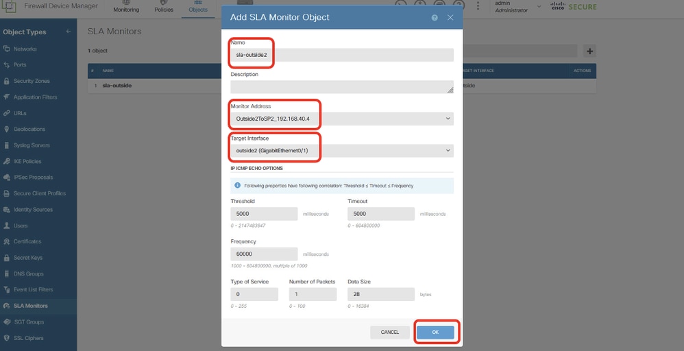
Step 19.2. Continue to click + button to create a new SLA monitor for ISP2 gateway. In the Add SLA Monitor Object window, provide necessary information for ISP2 gateway. Click OK button to save.
- Name: sla-outside2
- Monitor Adress: Outside2ToSP2_192.168.40.4
- Target Interface: outside2(GigabitEthernet0/1)
- IP ICMP ECHO OPTIONS: default
 Site1FTD_Create_SLAMonitor_NetObj_ISP2_Details
Step 20. Deploy the configuration changes.
 Site1FTD_Deployment_Changes
Site2 FTD SLA Monitor Configuration
Step 21. Repeat Step 18. to Step 20. create SLA Monitor with corresponding parameters on Site2 FTD.
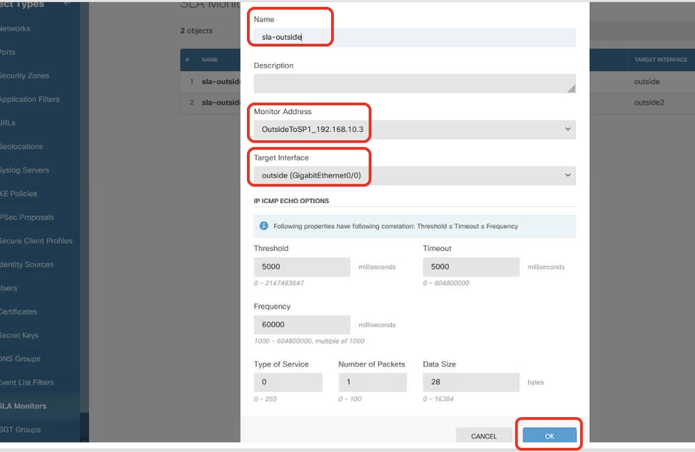 Site2FTD_Create_SLAMonitor_NetObj_ISP1_Details
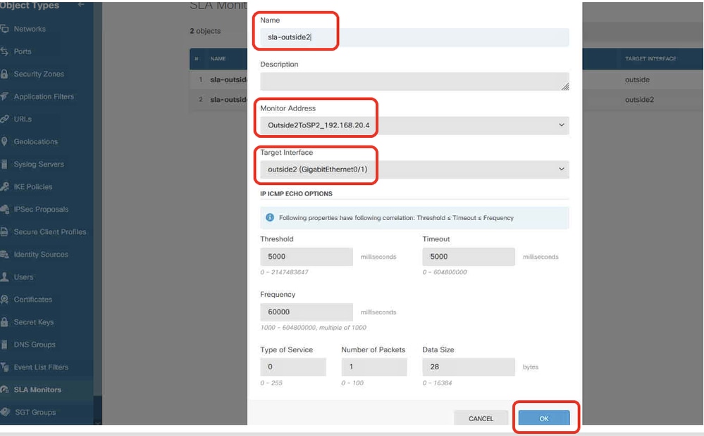 Site2FTD_Create_SLAMonitor_NetObj_ISP2_Details
Configurations on Static Route
Site1 FTD Static Route Configuration
Step 22. Create new network objects to be used by static route for Site1 FTD. Navigate to Objects > Networks, click + button.
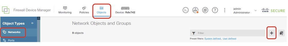 Site1FTD_Create_Obj
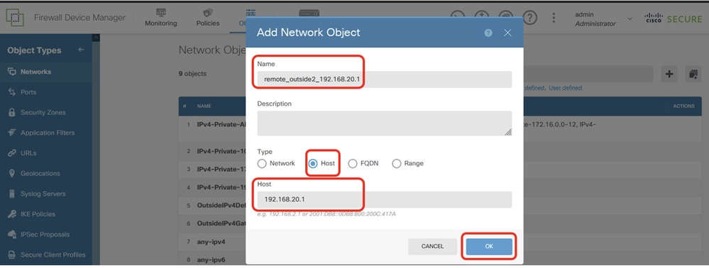
Step 22.1. Create object for outside2 IP address of peer Site2 FTD. Provide necessary information. Click OK button.
- Name: remote_outside2_192.168.20.1
- Type: HOST
- Network: 192.168.20.1
 Site1FTD_Create_NetObj_StaticRoute_1
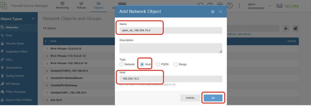
Step 22.2. Create object for VTI Tunnel1 IP address of peer Site2 FTD. Provide necessary information. Click OK button.
- Name: peer_vti_169.254.10.2
- Type: HOST
- Network:169.254.10.2
 Site1FTD_Create_NetObj_StaticRoute_2
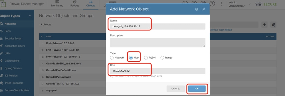
Step 22.3. Create object for VTI Tunnel2 IP address of peer Site2 FTD. Provide necessary information. Click OK button.
- Name: peer_vti_169.254.20.12
- Type: HOST
- Network:169.254.20.12
 Site1FTD_Create_NetObj_StaticRoute_3
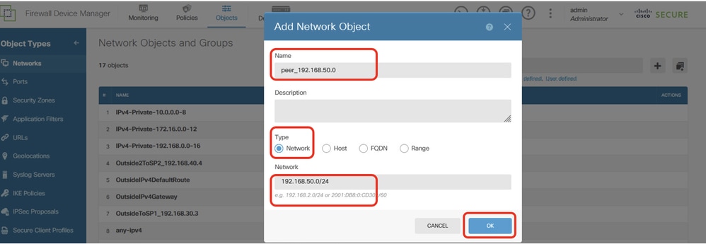
Step 22.4. Create object for inside network of peer Site2 FTD. Provide necessary information. Click OK button.
- Name: peer_192.168.50.0
- Type: NETWORK
- Network:192.168.50.0/24
 Site1FTD_Create_NetObj_StaticRoute_4
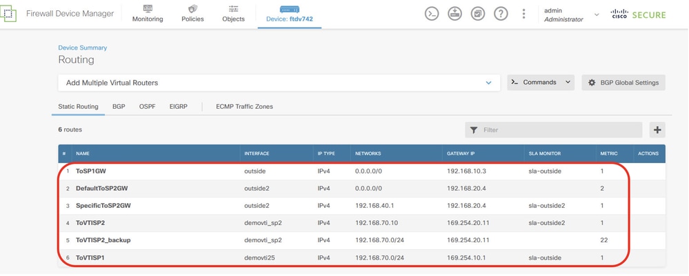
Step 23. Navigate to Device > Routing. Click View Configuration. Click Static Routing tab. Click + button to add new static route.
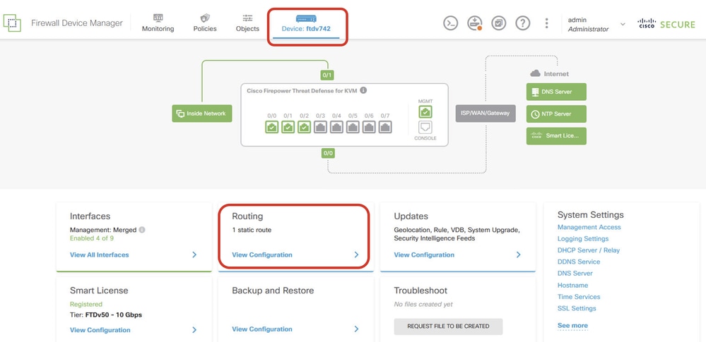 Site1FTD_View_Route_Configuration
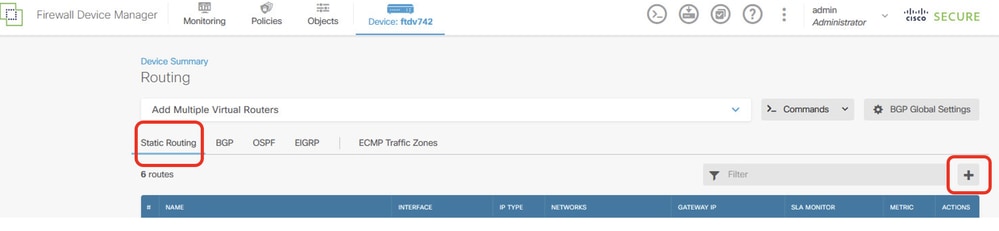 Site1FTD_Add_Static_Route
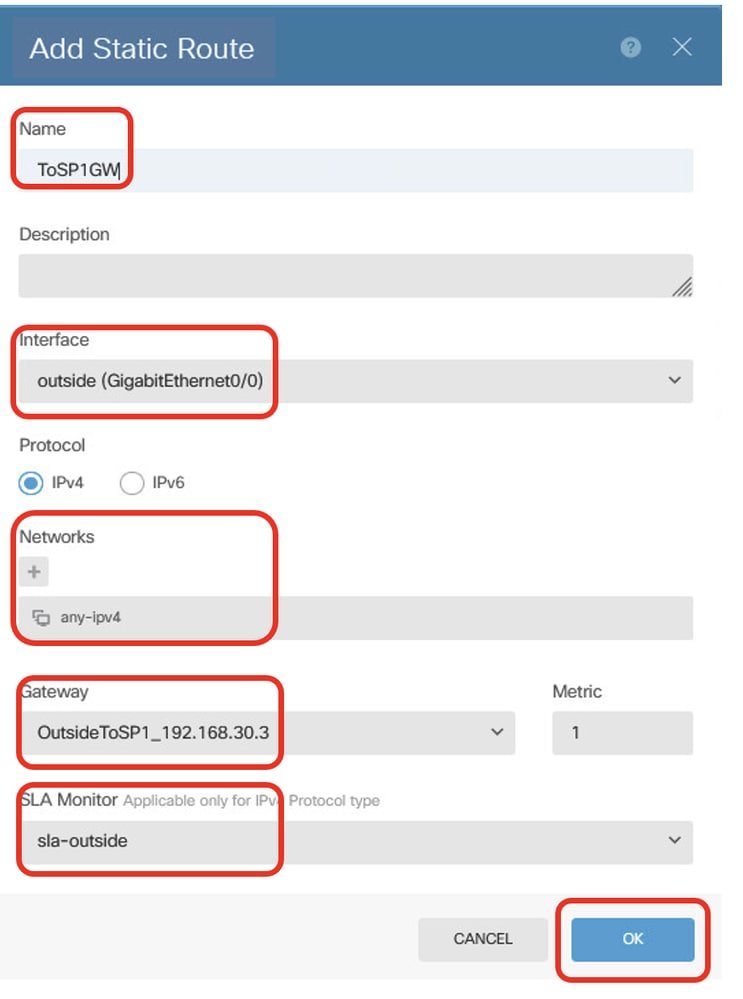
Step 23.1. Create a default route using the ISP1 gateway with SLA monitoring. If the ISP1 gateway experiences an interruption, traffic switches to the backup default route via ISP2. Once ISP1 recovers, traffic reverts to using ISP1. Provide necessary information. Click OK button to save.
- Name: ToSP1GW
- Interface: outside(GigabitEthernet0/0)
- Protocol: IPv4
- Networks: any-ipv4
- Gateway: OutsideToSP1_192.168.30.3
- Metric: 1
- SLA Monitor: sla-outside
 Site1FTD_Create_StaticRoute_1
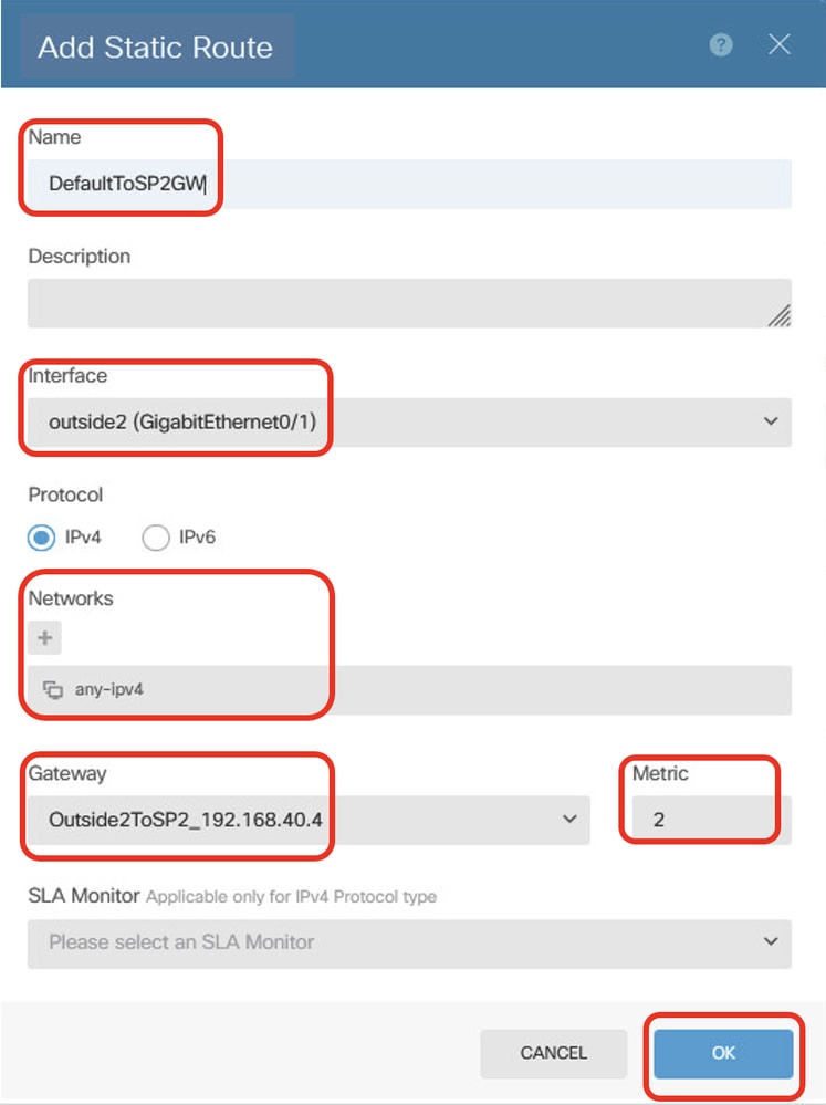
Step 23.2. Create backup default route via gateway ISP2 gateway. Metric must be higher than 1. In this example, metric is 2. Provide necessary information. Click OK button to save.
- Name: DefaultToSP2GW
- Interface: outside2(GigabitEthernet0/1)
- Protocol: IPv4
- Networks: any-ipv4
- Gateway: Outside2ToSP2_192.168.40.4
- Metric: 2
 Site1FTD_Create_StaticRoute_2
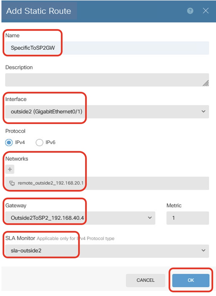
Step 23.3. Create static route for destination traffic to outside2 IP address of peer Site2 FTD via ISP2 gateway, with SLA monitoring, used for establishing VPN with outside2 of Site2 FTD. Provide necessary information. Click OK button to save.
- Name: SpecificToSP2GW
- Interface: outside2(GigabitEthernet0/1)
- Protocol: IPv4
- Networks: remote_outside2_192.168.20.1
- Gateway: Outside2ToSP2_192.168.40.4
- Metric: 1
- SLA Monitor: sla-outside2
 Site1FTD_Create_StaticRoute_3
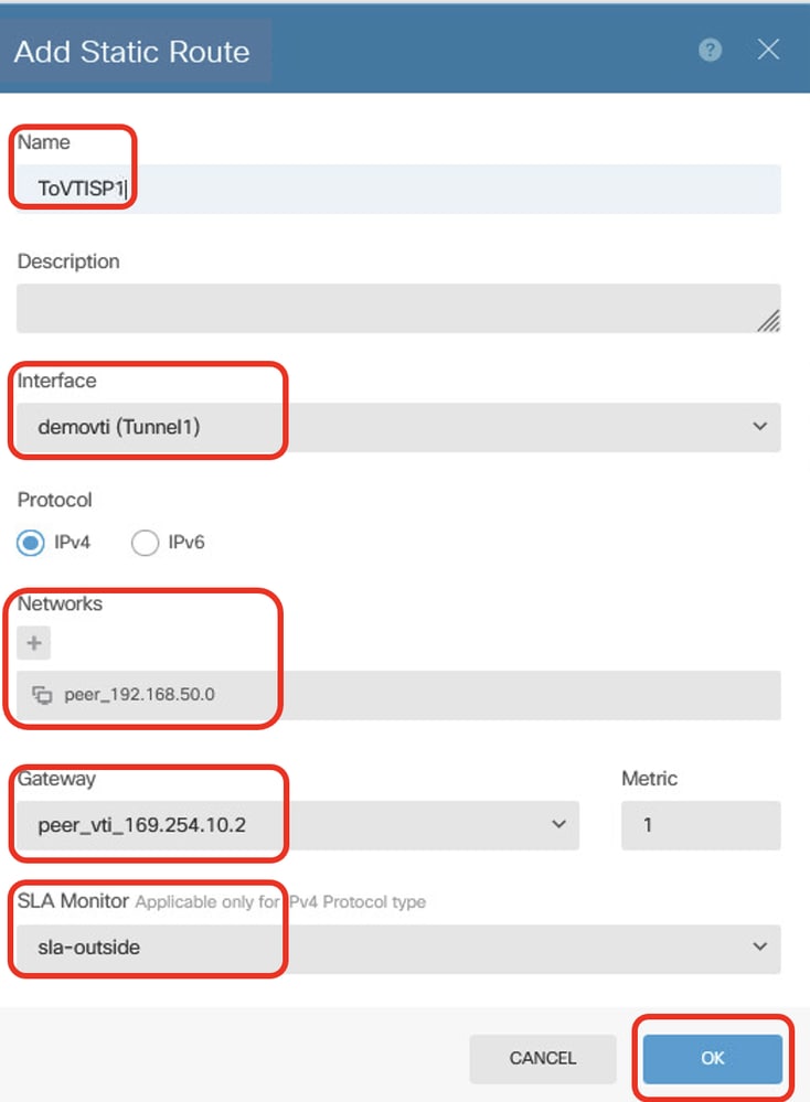
Step 23.4. Create a static route for destination traffic to the inside network of peer Site2 FTD via peer VTI Tunnel 1 of Site2 FTD as the gateway, with SLA monitoring for encrypting client traffic via Tunnel 1. If the ISP1 gateway experiences an interruption, VPN traffic switches to VTI Tunnel 2 of ISP2. Once ISP1 recovers, traffic reverts to VTI Tunnel 1 of ISP1. Provide necessary information. Click OK button to save.
- Name: ToVTISP1
- Interface: demovti(Tunnel1)
- Protocol: IPv4
- Networks: peer_192.168.50.0
- Gateway: peer_vti_169.254.10.2
- Metric: 1
- SLA Monitor: sla-outside
 Site1FTD_Create_StaticRoute_4
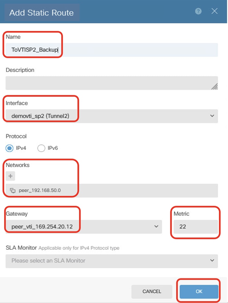
Step 23.5. Create a backup static route for destination traffic to the inside network of peer Site2 FTD via peer VTI Tunnel 2 of Site2 FTD as the gateway, used for encrypting client traffic via Tunnel 2. Set the metric to a value higher than 1. In this example, metric is 22. Provide necessary information. Click OK button to save.
- Name: ToVTISP2_Backup
- Interface: demovti_sp2(Tunnel2)
- Protocol: IPv4
- Networks: peer_192.168.50.0
- Gateway: peer_vti_169.254.20.12
- Metric: 22
 Site1FTD_Create_StaticRoute_5
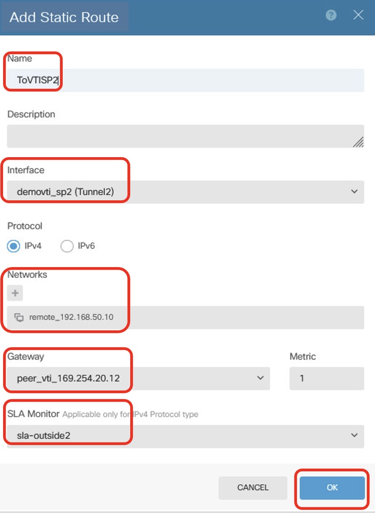
Step 23.6. Create static route for PBR traffic. Destination traffic to Site2 Client2 via peer VTI Tunnel 2 of Site2 FTD as gateway, with SLA monitoring. Provide necessary information. Click OK button to save.
- Name: ToVTISP2
- Interface: demovti_sp2(Tunnel2)
- Protocol: IPv4
- Networks: remote_192.168.50.10
- Gateway: peer_vti_169.254.20.12
- Metric: 1
- SLA Monitor: sla-outside2
 Site1FTD_Create_StaticRoute_6
Step 24. Deploy the configuration changes.
 Site1FTD_Deployment_Changes
Site2 FTD Static Route Configuration
Step 25. Repeat Steps 22 to 24 in order to create a static route with the corresponding parameters for Site2 FTD.
 Site2FTD_Create_StaticRoute
Verify
Use this section in order to confirm that your configuration works properly. Navigate to the CLI of Site1 FTD and Site2 FTD via console or SSH.
Both ISP1 and ISP2 Work Fine
VPN
//Site1 FTD:

ftdv742# show crypto ikev2 sa

IKEv2 SAs:

Session-id:156, Status:UP-ACTIVE, IKE count:1, CHILD count:1

Tunnel-id Local                                               Remote                                     fvrf/ivrf     Status         Role
1072332533 192.168.30.1/500                                    192.168.10.1/500                        Global/Global      READY    INITIATOR
      Encr: AES-CBC, keysize: 256, Hash: SHA256, DH Grp:14, Auth sign: PSK, Auth verify: PSK
      Life/Active Time: 86400/44895 sec
Child sa: local selector  0.0.0.0/0 - 255.255.255.255/65535
          remote selector 0.0.0.0/0 - 255.255.255.255/65535
          ESP spi in/out: 0xec031247/0xc2f3f549

IKEv2 SAs:

Session-id:148, Status:UP-ACTIVE, IKE count:1, CHILD count:1

Tunnel-id Local                                               Remote                                     fvrf/ivrf     Status         Role
1045734377 192.168.40.1/500                                    192.168.20.1/500                        Global/Global      READY    RESPONDER
      Encr: AES-CBC, keysize: 256, Hash: SHA256, DH Grp:14, Auth sign: PSK, Auth verify: PSK
      Life/Active Time: 86400/77860 sec
Child sa: local selector  0.0.0.0/0 - 255.255.255.255/65535
          remote selector 0.0.0.0/0 - 255.255.255.255/65535
          ESP spi in/out: 0x47bfa607/0x82e8781d
// Site2 FTD:
ftdv742# show crypto ikev2 sa
IKEv2 SAs:
Session-id:44, Status:UP-ACTIVE, IKE count:1, CHILD count:1
Tunnel-id Local Remote fvrf/ivrf Status Role
499259237 192.168.10.1/500 192.168.30.1/500 Global/Global READY RESPONDER
Encr: AES-CBC, keysize: 256, Hash: SHA256, DH Grp:14, Auth sign: PSK, Auth verify: PSK
Life/Active Time: 86400/44985 sec
Child sa: local selector 0.0.0.0/0 - 255.255.255.255/65535
remote selector 0.0.0.0/0 - 255.255.255.255/65535
ESP spi in/out: 0xc2f3f549/0xec031247
IKEv2 SAs:
Session-id:36, Status:UP-ACTIVE, IKE count:1, CHILD count:1
Tunnel-id Local Remote fvrf/ivrf Status Role
477599833 192.168.20.1/500 192.168.40.1/500 Global/Global READY INITIATOR
Encr: AES-CBC, keysize: 256, Hash: SHA256, DH Grp:14, Auth sign: PSK, Auth verify: PSK
Life/Active Time: 86400/77950 sec
Child sa: local selector 0.0.0.0/0 - 255.255.255.255/65535
remote selector 0.0.0.0/0 - 255.255.255.255/65535
ESP spi in/out: 0x82e8781d/0x47bfa607 Route
// Site1 FTD:

ftdv742# show route

Codes: L - local, C - connected, S - static, R - RIP, M - mobile, B - BGP
       D - EIGRP, EX - EIGRP external, O - OSPF, IA - OSPF inter area
       N1 - OSPF NSSA external type 1, N2 - OSPF NSSA external type 2
       E1 - OSPF external type 1, E2 - OSPF external type 2, V - VPN
       i - IS-IS, su - IS-IS summary, L1 - IS-IS level-1, L2 - IS-IS level-2
       ia - IS-IS inter area, * - candidate default, U - per-user static route
       o - ODR, P - periodic downloaded static route, + - replicated route
       SI - Static InterVRF, BI - BGP InterVRF
Gateway of last resort is 192.168.30.3 to network 0.0.0.0

S*       0.0.0.0 0.0.0.0 [1/0] via 192.168.30.3, outside
C        169.254.10.0 255.255.255.0 is directly connected, demovti
L        169.254.10.1 255.255.255.255 is directly connected, demovti
C        169.254.20.0 255.255.255.0 is directly connected, demovti_sp2
L        169.254.20.11 255.255.255.255 is directly connected, demovti_sp2
S        192.168.20.1 255.255.255.255 [1/0] via 192.168.40.4, outside2
C        192.168.30.0 255.255.255.0 is directly connected, outside
L        192.168.30.1 255.255.255.255 is directly connected, outside
C        192.168.40.0 255.255.255.0 is directly connected, outside2
L        192.168.40.1 255.255.255.255 is directly connected, outside2
S        192.168.50.0 255.255.255.0 [1/0] via 169.254.10.2, demovti
S        192.168.50.10 255.255.255.255 [1/0] via 169.254.20.12, demovti_sp2
C        192.168.70.0 255.255.255.0 is directly connected, inside
L        192.168.70.1 255.255.255.255 is directly connected, inside
// Site2 FTD:
ftdv742# show route
Codes: L - local, C - connected, S - static, R - RIP, M - mobile, B - BGP
D - EIGRP, EX - EIGRP external, O - OSPF, IA - OSPF inter area
N1 - OSPF NSSA external type 1, N2 - OSPF NSSA external type 2
E1 - OSPF external type 1, E2 - OSPF external type 2, V - VPN
i - IS-IS, su - IS-IS summary, L1 - IS-IS level-1, L2 - IS-IS level-2
ia - IS-IS inter area, * - candidate default, U - per-user static route
o - ODR, P - periodic downloaded static route, + - replicated route
SI - Static InterVRF, BI - BGP InterVRF
Gateway of last resort is 192.168.10.3 to network 0.0.0.0
S* 0.0.0.0 0.0.0.0 [1/0] via 192.168.10.3, outside
C 169.254.10.0 255.255.255.0 is directly connected, demovti25
L 169.254.10.2 255.255.255.255 is directly connected, demovti25
C 169.254.20.0 255.255.255.0 is directly connected, demovti_sp2
L 169.254.20.12 255.255.255.255 is directly connected, demovti_sp2
C 192.168.10.0 255.255.255.0 is directly connected, outside
L 192.168.10.1 255.255.255.255 is directly connected, outside
C 192.168.20.0 255.255.255.0 is directly connected, outside2
L 192.168.20.1 255.255.255.255 is directly connected, outside2
S 192.168.40.1 255.255.255.255 [1/0] via 192.168.20.4, outside2
C 192.168.50.0 255.255.255.0 is directly connected, inside
L 192.168.50.1 255.255.255.255 is directly connected, inside
S 192.168.70.0 255.255.255.0 [1/0] via 169.254.10.1, demovti25
S 192.168.70.10 255.255.255.255 [1/0] via 169.254.20.11, demovti_sp2SLA Monitor
// Site1 FTD:

ftdv742# show sla monitor configuration
SA Agent, Infrastructure Engine-II
Entry number: 188426425
Owner:
Tag:
Type of operation to perform: echo
Target address: 192.168.40.4
Interface: outside2
Number of packets: 1
Request size (ARR data portion): 28
Operation timeout (milliseconds): 5000
Type Of Service parameters: 0x0
Verify data: No
Operation frequency (seconds): 60
Next Scheduled Start Time: Start Time already passed
Group Scheduled : FALSE
Life (seconds): Forever
Entry Ageout (seconds): never
Recurring (Starting Everyday): FALSE
Status of entry (SNMP RowStatus): Active
Enhanced History:

Entry number: 855903900
Owner:
Tag:
Type of operation to perform: echo
Target address: 192.168.30.3
Interface: outside
Number of packets: 1
Request size (ARR data portion): 28
Operation timeout (milliseconds): 5000
Type Of Service parameters: 0x0
Verify data: No
Operation frequency (seconds): 60
Next Scheduled Start Time: Start Time already passed
Group Scheduled : FALSE
Life (seconds): Forever
Entry Ageout (seconds): never
Recurring (Starting Everyday): FALSE
Status of entry (SNMP RowStatus): Active
Enhanced History:


ftdv742# show sla monitor operational-state
Entry number: 188426425
Modification time: 08:37:05.132 UTC Wed Aug 14 2024
Number of Octets Used by this Entry: 2056
Number of operations attempted: 1748
Number of operations skipped: 0
Current seconds left in Life: Forever
Operational state of entry: Active
Last time this entry was reset: Never
Connection loss occurred: FALSE
Timeout occurred: FALSE
Over thresholds occurred: FALSE
Latest RTT (milliseconds): 30
Latest operation start time: 13:44:05.173 UTC Thu Aug 15 2024
Latest operation return code: OK
RTT Values:
RTTAvg: 30	RTTMin: 30	RTTMax: 30
NumOfRTT: 1	RTTSum: 30	RTTSum2: 900

Entry number: 855903900
Modification time: 08:37:05.133 UTC Wed Aug 14 2024
Number of Octets Used by this Entry: 2056
Number of operations attempted: 1748
Number of operations skipped: 0
Current seconds left in Life: Forever
Operational state of entry: Active
Last time this entry was reset: Never
Connection loss occurred: FALSE
Timeout occurred: FALSE
Over thresholds occurred: FALSE
Latest RTT (milliseconds): 30
Latest operation start time: 13:44:05.178 UTC Thu Aug 15 2024
Latest operation return code: OK
RTT Values:
RTTAvg: 30	RTTMin: 30	RTTMax: 30
NumOfRTT: 1	RTTSum: 30	RTTSum2: 900
// Site2 FTD:

ftdv742#  show sla monitor configuration
SA Agent, Infrastructure Engine-II
Entry number: 550063734
Owner:
Tag:
Type of operation to perform: echo
Target address: 192.168.20.4
Interface: outside2
Number of packets: 1
Request size (ARR data portion): 28
Operation timeout (milliseconds): 5000
Type Of Service parameters: 0x0
Verify data: No
Operation frequency (seconds): 60
Next Scheduled Start Time: Start Time already passed
Group Scheduled : FALSE
Life (seconds): Forever
Entry Ageout (seconds): never
Recurring (Starting Everyday): FALSE
Status of entry (SNMP RowStatus): Active
Enhanced History:

Entry number: 609724264
Owner:
Tag:
Type of operation to perform: echo
Target address: 192.168.10.3
Interface: outside
Number of packets: 1
Request size (ARR data portion): 28
Operation timeout (milliseconds): 5000
Type Of Service parameters: 0x0
Verify data: No
Operation frequency (seconds): 60
Next Scheduled Start Time: Start Time already passed
Group Scheduled : FALSE
Life (seconds): Forever
Entry Ageout (seconds): never
Recurring (Starting Everyday): FALSE
Status of entry (SNMP RowStatus): Active
Enhanced History:

ftdv742# show sla monitor operational-state
Entry number: 550063734
Modification time: 09:05:52.864 UTC Wed Aug 14 2024
Number of Octets Used by this Entry: 2056
Number of operations attempted: 1718
Number of operations skipped: 0
Current seconds left in Life: Forever
Operational state of entry: Active
Last time this entry was reset: Never
Connection loss occurred: FALSE
Timeout occurred: FALSE
Over thresholds occurred: FALSE
Latest RTT (milliseconds): 190
Latest operation start time: 13:42:52.916 UTC Thu Aug 15 2024
Latest operation return code: OK
RTT Values:
RTTAvg: 190	RTTMin: 190	RTTMax: 190
NumOfRTT: 1	RTTSum: 190	RTTSum2: 36100

Entry number: 609724264
Modification time: 09:05:52.856 UTC Wed Aug 14 2024
Number of Octets Used by this Entry: 2056
Number of operations attempted: 1718
Number of operations skipped: 0
Current seconds left in Life: Forever
Operational state of entry: Active
Last time this entry was reset: Never
Connection loss occurred: FALSE
Timeout occurred: FALSE
Over thresholds occurred: FALSE
Latest RTT (milliseconds): 190
Latest operation start time: 13:42:52.921 UTC Thu Aug 15 2024
Latest operation return code: OK
RTT Values:
RTTAvg: 190	RTTMin: 190	RTTMax: 190
NumOfRTT: 1	RTTSum: 190	RTTSum2: 36100
Ping Test
Scenario 1. Site1 Client1 ping Site2 Client1.
Before ping, check the counters of show crypto ipsec sa | inc interface:|encap|decap on Site1 FTD.
In this example, Tunnel1 shows 1497 packets for encapsulation and 1498 packets for decapsulation.
// Site1 FTD:

ftdv742# show crypto ipsec sa | inc interface:|encap|decap
interface: demovti
      #pkts encaps: 1497, #pkts encrypt: 1497, #pkts digest: 1497
      #pkts decaps: 1498, #pkts decrypt: 1498, #pkts verify: 1498
      #PMTUs sent: 0, #PMTUs rcvd: 0, #decapsulated frgs needing reassembly: 0
interface: demovti_sp2
      #pkts encaps: 16, #pkts encrypt: 16, #pkts digest: 16
      #pkts decaps: 15, #pkts decrypt: 15, #pkts verify: 15
      #PMTUs sent: 0, #PMTUs rcvd: 0, #decapsulated frgs needing reassembly: 0
Site1 Client1 ping Site2 Client1 successfully.
Site1_Client1#ping 192.168.50.2
Type escape sequence to abort.
Sending 5, 100-byte ICMP Echos to 192.168.50.2, timeout is 2 seconds:
!!!!!
Success rate is 100 percent (5/5), round-trip min/avg/max = 10/97/227 ms
Check the counters of show crypto ipsec sa | inc interface:|encap|decap on Site1 FTD after ping successfully.
In this example, Tunnel 1 shows 1502 packets for encapsulation and 1503 packets for decapsulation, with both counters increasing by 5 packets, matching the 5 ping echo requests. This indicates that pings of Site1 Client1 to Site2 Client1 are routed via ISP1 Tunnel 1. Tunnel 2 shows no increase in encapsulation or decapsulation counters, confirming it is not being used for this traffic.
// Site1 FTD:

ftdv742# show crypto ipsec sa | inc interface:|encap|decap
interface: demovti
      #pkts encaps: 1502, #pkts encrypt: 1502, #pkts digest: 1502
      #pkts decaps: 1503, #pkts decrypt: 1503, #pkts verify: 1503
      #PMTUs sent: 0, #PMTUs rcvd: 0, #decapsulated frgs needing reassembly: 0
interface: demovti_sp2
      #pkts encaps: 16, #pkts encrypt: 16, #pkts digest: 16
      #pkts decaps: 15, #pkts decrypt: 15, #pkts verify: 15
      #PMTUs sent: 0, #PMTUs rcvd: 0, #decapsulated frgs needing reassembly: 0
Scenario 2. Site1 Client2 ping Site2 Client2.
Before ping, check the counters of show crypto ipsec sa | inc interface:|encap|decap on Site1 FTD.
In this example, Tunnel2 shows 21 packets for encapsulation and 20 packets for decapsulation.
// Site1 FTD:

ftdv742# show crypto ipsec sa | inc interface:|encap|decap
interface: demovti
      #pkts encaps: 1520, #pkts encrypt: 1520, #pkts digest: 1520
      #pkts decaps: 1521, #pkts decrypt: 1521, #pkts verify: 1521
      #PMTUs sent: 0, #PMTUs rcvd: 0, #decapsulated frgs needing reassembly: 0
interface: demovti_sp2
      #pkts encaps: 21, #pkts encrypt: 21, #pkts digest: 21
      #pkts decaps: 20, #pkts decrypt: 20, #pkts verify: 20
      #PMTUs sent: 0, #PMTUs rcvd: 0, #decapsulated frgs needing reassembly: 0
Site1 Client2 ping Site2 Client2 successfully.
Site1_Client2#ping 192.168.50.10
Type escape sequence to abort.
Sending 5, 100-byte ICMP Echos to 192.168.50.10, timeout is 2 seconds:
!!!!!
Success rate is 100 percent (5/5), round-trip min/avg/max = 4/39/87 ms
Check the counters of show crypto ipsec sa | inc interface:|encap|decap on Site1 FTD after ping successfully.
In this example, Tunnel 2 shows 26 packets for encapsulation and 25 packets for decapsulation, with both counters increasing by 5 packets, matching the 5 ping echo requests. This indicates that pings of Site1 Client2 to Site2 Client2 are routed via ISP2 Tunnel 2. Tunnel 1 shows no increase in encapsulation or decapsulation counters, confirming it is not being used for this traffic.
// Site1 FTD:

ftdv742# show crypto ipsec sa | inc interface:|encap|decap
interface: demovti
      #pkts encaps: 1520, #pkts encrypt: 1520, #pkts digest: 1520
      #pkts decaps: 1521, #pkts decrypt: 1521, #pkts verify: 1521
      #PMTUs sent: 0, #PMTUs rcvd: 0, #decapsulated frgs needing reassembly: 0
interface: demovti_sp2
      #pkts encaps: 26, #pkts encrypt: 26, #pkts digest: 26
      #pkts decaps: 25, #pkts decrypt: 25, #pkts verify: 25
      #PMTUs sent: 0, #PMTUs rcvd: 0, #decapsulated frgs needing reassembly: 0
ISP1 Experiences an Interruption While ISP2 Works Fine
In this example, manual shutdown the interface E0/1 on ISP1 to simulate the ISP1 experiencing an interruption.
Internet_SP1#conf t
Enter configuration commands, one per line.  End with CNTL/Z.
Internet_SP1(config)#
Internet_SP1(config)#interface E0/1
Internet_SP1(config-if)#shutdown
Internet_SP1(config-if)#exit
Internet_SP1(config)#
VPN
The Tunnel1 went down. Only Tunnel2 is active with IKEV2 SA.
// Site1 FTD:

ftdv742# show interface tunnel 1
Interface Tunnel1 "demovti", is down, line protocol is down
  Hardware is Virtual Tunnel	MAC address N/A, MTU 1500
	IP address 169.254.10.1, subnet mask 255.255.255.0
  Tunnel Interface Information:
	Source interface: outside	IP address: 192.168.30.1
	Destination IP address: 192.168.10.1
	IPsec MTU Overhead : 0
	Mode: ipsec ipv4	IPsec profile: ipsec_profile|e4084d322d


ftdv742# show crypto ikev2 sa

IKEv2 SAs:

Session-id:148, Status:UP-ACTIVE, IKE count:1, CHILD count:1

Tunnel-id Local                                               Remote                                     fvrf/ivrf     Status         Role
1045734377 192.168.40.1/500                                    192.168.20.1/500                        Global/Global      READY    RESPONDER
      Encr: AES-CBC, keysize: 256, Hash: SHA256, DH Grp:14, Auth sign: PSK, Auth verify: PSK
      Life/Active Time: 86400/80266 sec
Child sa: local selector  0.0.0.0/0 - 255.255.255.255/65535
          remote selector 0.0.0.0/0 - 255.255.255.255/65535
          ESP spi in/out: 0x47bfa607/0x82e8781d
// Site2 FTD:
ftdv742# show interface tunnel 1
Interface Tunnel1 "demovti25", is down, line protocol is down
Hardware is Virtual Tunnel MAC address N/A, MTU 1500
IP address 169.254.10.2, subnet mask 255.255.255.0
Tunnel Interface Information:
Source interface: outside IP address: 192.168.10.1
Destination IP address: 192.168.30.1
IPsec MTU Overhead : 0
Mode: ipsec ipv4 IPsec profile: ipsec_profile|e4084d322d
ftdv742#
ftdv742# show crypto ikev2 sa
IKEv2 SAs:
Session-id:36, Status:UP-ACTIVE, IKE count:1, CHILD count:1
Tunnel-id Local Remote fvrf/ivrf Status Role
477599833 192.168.20.1/500 192.168.40.1/500 Global/Global READY INITIATOR
Encr: AES-CBC, keysize: 256, Hash: SHA256, DH Grp:14, Auth sign: PSK, Auth verify: PSK
Life/Active Time: 86400/80382 sec
Child sa: local selector 0.0.0.0/0 - 255.255.255.255/65535
remote selector 0.0.0.0/0 - 255.255.255.255/65535
ESP spi in/out: 0x82e8781d/0x47bfa607 Route
In route table, the backup routes take effect.
// Site1 FTD:

ftdv742# show route

Codes: L - local, C - connected, S - static, R - RIP, M - mobile, B - BGP
       D - EIGRP, EX - EIGRP external, O - OSPF, IA - OSPF inter area
       N1 - OSPF NSSA external type 1, N2 - OSPF NSSA external type 2
       E1 - OSPF external type 1, E2 - OSPF external type 2, V - VPN
       i - IS-IS, su - IS-IS summary, L1 - IS-IS level-1, L2 - IS-IS level-2
       ia - IS-IS inter area, * - candidate default, U - per-user static route
       o - ODR, P - periodic downloaded static route, + - replicated route
       SI - Static InterVRF, BI - BGP InterVRF
Gateway of last resort is 192.168.40.4 to network 0.0.0.0

S*       0.0.0.0 0.0.0.0 [2/0] via 192.168.40.4, outside2
C        169.254.20.0 255.255.255.0 is directly connected, demovti_sp2
L        169.254.20.11 255.255.255.255 is directly connected, demovti_sp2
S        192.168.20.1 255.255.255.255 [1/0] via 192.168.40.4, outside2
C        192.168.30.0 255.255.255.0 is directly connected, outside
L        192.168.30.1 255.255.255.255 is directly connected, outside
C        192.168.40.0 255.255.255.0 is directly connected, outside2
L        192.168.40.1 255.255.255.255 is directly connected, outside2
S        192.168.50.0 255.255.255.0 [22/0] via 169.254.20.12, demovti_sp2
S        192.168.50.10 255.255.255.255 [1/0] via 169.254.20.12, demovti_sp2
C        192.168.70.0 255.255.255.0 is directly connected, inside
L        192.168.70.1 255.255.255.255 is directly connected, inside
// Site2 FTD:
ftdv742# show route
Codes: L - local, C - connected, S - static, R - RIP, M - mobile, B - BGP
D - EIGRP, EX - EIGRP external, O - OSPF, IA - OSPF inter area
N1 - OSPF NSSA external type 1, N2 - OSPF NSSA external type 2
E1 - OSPF external type 1, E2 - OSPF external type 2, V - VPN
i - IS-IS, su - IS-IS summary, L1 - IS-IS level-1, L2 - IS-IS level-2
ia - IS-IS inter area, * - candidate default, U - per-user static route
o - ODR, P - periodic downloaded static route, + - replicated route
SI - Static InterVRF, BI - BGP InterVRF
Gateway of last resort is 192.168.10.3 to network 0.0.0.0
S* 0.0.0.0 0.0.0.0 [1/0] via 192.168.10.3, outside
C 169.254.20.0 255.255.255.0 is directly connected, demovti_sp2
L 169.254.20.12 255.255.255.255 is directly connected, demovti_sp2
C 192.168.10.0 255.255.255.0 is directly connected, outside
L 192.168.10.1 255.255.255.255 is directly connected, outside
C 192.168.20.0 255.255.255.0 is directly connected, outside2
L 192.168.20.1 255.255.255.255 is directly connected, outside2
S 192.168.40.1 255.255.255.255 [1/0] via 192.168.20.4, outside2
C 192.168.50.0 255.255.255.0 is directly connected, inside
L 192.168.50.1 255.255.255.255 is directly connected, inside
S 192.168.70.0 255.255.255.0 [22/0] via 169.254.20.11, demovti_sp2
S 192.168.70.10 255.255.255.255 [1/0] via 169.254.20.11, demovti_sp2SLA Monitor
On Site1 FTD, the SLA monitor shows entry number 855903900 timeout (Target address is 192.168.30.3) for ISP1.
// Site1 FTD:

ftdv742# show sla monitor operational-state
Entry number: 188426425
Modification time: 08:37:05.131 UTC Wed Aug 14 2024
Number of Octets Used by this Entry: 2056
Number of operations attempted: 1786
Number of operations skipped: 0
Current seconds left in Life: Forever
Operational state of entry: Active
Last time this entry was reset: Never
Connection loss occurred: FALSE
Timeout occurred: FALSE
Over thresholds occurred: FALSE
Latest RTT (milliseconds): 100
Latest operation start time: 14:22:05.132 UTC Thu Aug 15 2024
Latest operation return code: OK
RTT Values:
RTTAvg: 100	RTTMin: 100	RTTMax: 100
NumOfRTT: 1	RTTSum: 100	RTTSum2: 10000

Entry number: 855903900
Modification time: 08:37:05.132 UTC Wed Aug 14 2024
Number of Octets Used by this Entry: 2056
Number of operations attempted: 1786
Number of operations skipped: 0
Current seconds left in Life: Forever
Operational state of entry: Active
Last time this entry was reset: Never
Connection loss occurred: FALSE
Timeout occurred: TRUE
Over thresholds occurred: FALSE
Latest RTT (milliseconds): NoConnection/Busy/Timeout
Latest operation start time: 14:22:05.134 UTC Thu Aug 15 2024
Latest operation return code: Timeout
RTT Values:
RTTAvg: 0	RTTMin: 0	RTTMax: 0
NumOfRTT: 0	RTTSum: 0	RTTSum2: 0

ftdv742# show track
Track 1
  Response Time Reporter 855903900 reachability
  Reachability is Down
  7 changes, last change 00:11:03
  Latest operation return code: Timeout
  Tracked by:
    STATIC-IP-ROUTING 0
Track 2
  Response Time Reporter 188426425 reachability
  Reachability is Up
  4 changes, last change 13:15:11
  Latest operation return code: OK
  Latest RTT (millisecs) 140
  Tracked by:
    STATIC-IP-ROUTING 0
Ping Test
Before ping, check the counters of show crypto ipsec sa | inc interface:|encap|decap on Site1 FTD.
In this example, Tunnel2 shows 36 packets for encapsulation and 35 packets for decapsulation.
// Site1 FTD:

ftdv742# show crypto ipsec sa | inc interface:|encap|decap
interface: demovti_sp2
      #pkts encaps: 36, #pkts encrypt: 36, #pkts digest: 36
      #pkts decaps: 35, #pkts decrypt: 35, #pkts verify: 35
      #PMTUs sent: 0, #PMTUs rcvd: 0, #decapsulated frgs needing reassembly: 0
Site1 Client1 ping Site2 Client1 successfully.
Site1_Client1#ping 192.168.50.2
Type escape sequence to abort.
Sending 5, 100-byte ICMP Echos to 192.168.50.2, timeout is 2 seconds:
!!!!!
Success rate is 100 percent (5/5), round-trip min/avg/max = 22/133/253 ms
Site1 Client2 ping Site2 Client2 successfully.
Site1_Client2#ping 192.168.50.10
Type escape sequence to abort.
Sending 5, 100-byte ICMP Echos to 192.168.50.10, timeout is 2 seconds:
!!!!!
Success rate is 100 percent (5/5), round-trip min/avg/max = 34/56/87 ms
Check the counters of show crypto ipsec sa | inc interface:|encap|decap on Site1 FTD after ping sucessfully.
In this example, Tunnel 2 shows 46 packets for encapsulation and 45 packets for decapsulation, with both counters increasing by 10 packets, matching the 10 ping echo requests. This indicates that the ping packets are routed via ISP2 Tunnel 2.
// Site1 FTD:

ftdv742# show crypto ipsec sa | inc interface:|encap|decap
interface: demovti_sp2
      #pkts encaps: 46, #pkts encrypt: 46, #pkts digest: 46
      #pkts decaps: 45, #pkts decrypt: 45, #pkts verify: 45
      #PMTUs sent: 0, #PMTUs rcvd: 0, #decapsulated frgs needing reassembly: 0
ISP2 Experiences an Interruption While ISP1 Works Fine
In this example, manual shutdown the interface E0/1 on ISP2 to simulate the ISP2 experiencing an interruption.
Internet_SP2#conf t
Enter configuration commands, one per line.  End with CNTL/Z.
Internet_SP2(config)#
Internet_SP2(config)#int e0/1
Internet_SP2(config-if)#shutdown
Internet_SP2(config-if)#^Z
Internet_SP2#
VPN
The Tunnel2 went down. Only Tunnel1 is active with IKEV2 SA.
// Site1 FTD:

ftdv742# show interface tunnel 2
Interface Tunnel2 "demovti_sp2", is down, line protocol is down
  Hardware is Virtual Tunnel	MAC address N/A, MTU 1500
	IP address 169.254.20.11, subnet mask 255.255.255.0
  Tunnel Interface Information:
	Source interface: outside2	IP address: 192.168.40.1
	Destination IP address: 192.168.20.1
	IPsec MTU Overhead : 0
	Mode: ipsec ipv4	IPsec profile: ipsec_profile|e4084d322d

ftdv742# show crypto ikev2 sa

IKEv2 SAs:

Session-id:159, Status:UP-ACTIVE, IKE count:1, CHILD count:1

Tunnel-id Local                                               Remote                                     fvrf/ivrf     Status         Role
1375077093 192.168.30.1/500                                    192.168.10.1/500                        Global/Global      READY    INITIATOR
      Encr: AES-CBC, keysize: 256, Hash: SHA256, DH Grp:14, Auth sign: PSK, Auth verify: PSK
      Life/Active Time: 86400/349 sec
Child sa: local selector  0.0.0.0/0 - 255.255.255.255/65535
          remote selector 0.0.0.0/0 - 255.255.255.255/65535
          ESP spi in/out: 0x40f407b4/0x26598bcc
// Site2 FTD:
ftdv742# show int tunnel 2
Interface Tunnel2 "demovti_sp2", is down, line protocol is down
Hardware is Virtual Tunnel MAC address N/A, MTU 1500
IP address 169.254.20.12, subnet mask 255.255.255.0
Tunnel Interface Information:
Source interface: outside2 IP address: 192.168.20.1
Destination IP address: 192.168.40.1
IPsec MTU Overhead : 0
Mode: ipsec ipv4 IPsec profile: ipsec_profile|e4084d322d
ftdv742# show crypto ikev2 sa
IKEv2 SAs:
Session-id:165, Status:UP-ACTIVE, IKE count:1, CHILD count:1
Tunnel-id Local Remote fvrf/ivrf Status Role
1025640731 192.168.10.1/500 192.168.30.1/500 Global/Global READY RESPONDER
Encr: AES-CBC, keysize: 256, Hash: SHA256, DH Grp:14, Auth sign: PSK, Auth verify: PSK
Life/Active Time: 86400/379 sec
Child sa: local selector 0.0.0.0/0 - 255.255.255.255/65535
remote selector 0.0.0.0/0 - 255.255.255.255/65535
ESP spi in/out: 0x26598bcc/0x40f407b4 Route
In route table, ISP2 related route disapeared for PBR traffic.
// Site1 FTD:

ftdv742# show route

Codes: L - local, C - connected, S - static, R - RIP, M - mobile, B - BGP
       D - EIGRP, EX - EIGRP external, O - OSPF, IA - OSPF inter area
       N1 - OSPF NSSA external type 1, N2 - OSPF NSSA external type 2
       E1 - OSPF external type 1, E2 - OSPF external type 2, V - VPN
       i - IS-IS, su - IS-IS summary, L1 - IS-IS level-1, L2 - IS-IS level-2
       ia - IS-IS inter area, * - candidate default, U - per-user static route
       o - ODR, P - periodic downloaded static route, + - replicated route
       SI - Static InterVRF, BI - BGP InterVRF
Gateway of last resort is 192.168.30.3 to network 0.0.0.0

S*       0.0.0.0 0.0.0.0 [1/0] via 192.168.30.3, outside
C        169.254.10.0 255.255.255.0 is directly connected, demovti
L        169.254.10.1 255.255.255.255 is directly connected, demovti
C        192.168.30.0 255.255.255.0 is directly connected, outside
L        192.168.30.1 255.255.255.255 is directly connected, outside
C        192.168.40.0 255.255.255.0 is directly connected, outside2
L        192.168.40.1 255.255.255.255 is directly connected, outside2
S        192.168.50.0 255.255.255.0 [1/0] via 169.254.10.2, demovti
C        192.168.70.0 255.255.255.0 is directly connected, inside
L        192.168.70.1 255.255.255.255 is directly connected, inside
// Site2 FTD:
ftdv742# show route
Codes: L - local, C - connected, S - static, R - RIP, M - mobile, B - BGP
D - EIGRP, EX - EIGRP external, O - OSPF, IA - OSPF inter area
N1 - OSPF NSSA external type 1, N2 - OSPF NSSA external type 2
E1 - OSPF external type 1, E2 - OSPF external type 2, V - VPN
i - IS-IS, su - IS-IS summary, L1 - IS-IS level-1, L2 - IS-IS level-2
ia - IS-IS inter area, * - candidate default, U - per-user static route
o - ODR, P - periodic downloaded static route, + - replicated route
SI - Static InterVRF, BI - BGP InterVRF
Gateway of last resort is 192.168.10.3 to network 0.0.0.0
S* 0.0.0.0 0.0.0.0 [1/0] via 192.168.10.3, outside
C 169.254.10.0 255.255.255.0 is directly connected, demovti25
L 169.254.10.2 255.255.255.255 is directly connected, demovti25
C 192.168.10.0 255.255.255.0 is directly connected, outside
L 192.168.10.1 255.255.255.255 is directly connected, outside
C 192.168.20.0 255.255.255.0 is directly connected, outside2
L 192.168.20.1 255.255.255.255 is directly connected, outside2
S 192.168.40.1 255.255.255.255 [1/0] via 192.168.20.4, outside2
C 192.168.50.0 255.255.255.0 is directly connected, inside
L 192.168.50.1 255.255.255.255 is directly connected, inside
S 192.168.70.0 255.255.255.0 [1/0] via 169.254.10.1, demovti25SLA Monitor
On Site1 FTD, the SLA monitor shows entry number 188426425 timeout (Target address is 192.168.40.4) for ISP2.
// Site1 FTD:

ftdv742# show sla monitor operational-state
Entry number: 188426425
Modification time: 08:37:05.133 UTC Wed Aug 14 2024
Number of Octets Used by this Entry: 2056
Number of operations attempted: 1816
Number of operations skipped: 0
Current seconds left in Life: Forever
Operational state of entry: Active
Last time this entry was reset: Never
Connection loss occurred: FALSE
Timeout occurred: TRUE
Over thresholds occurred: FALSE
Latest RTT (milliseconds): NoConnection/Busy/Timeout
Latest operation start time: 14:52:05.174 UTC Thu Aug 15 2024
Latest operation return code: Timeout
RTT Values:
RTTAvg: 0	RTTMin: 0	RTTMax: 0
NumOfRTT: 0	RTTSum: 0	RTTSum2: 0

Entry number: 855903900
Modification time: 08:37:05.135 UTC Wed Aug 14 2024
Number of Octets Used by this Entry: 2056
Number of operations attempted: 1816
Number of operations skipped: 0
Current seconds left in Life: Forever
Operational state of entry: Active
Last time this entry was reset: Never
Connection loss occurred: FALSE
Timeout occurred: FALSE
Over thresholds occurred: FALSE
Latest RTT (milliseconds): 10
Latest operation start time: 14:52:05.177 UTC Thu Aug 15 2024
Latest operation return code: OK
RTT Values:
RTTAvg: 10	RTTMin: 10	RTTMax: 10
NumOfRTT: 1	RTTSum: 10	RTTSum2: 100


ftdv742#  show track
Track 1
  Response Time Reporter 855903900 reachability
  Reachability is Up
  8 changes, last change 00:14:37
  Latest operation return code: OK
  Latest RTT (millisecs) 60
  Tracked by:
    STATIC-IP-ROUTING 0
Track 2
  Response Time Reporter 188426425 reachability
  Reachability is Down
  5 changes, last change 00:09:30
  Latest operation return code: Timeout
  Tracked by:
    STATIC-IP-ROUTING 0
Ping Test
Before ping, check the counters of show crypto ipsec sa | inc interface:|encap|decap on Site1 FTD.
In this example, Tunnel 1 shows 74 packets for encapsulation and 73 packets for decapsulation.
// Site1 FTD:

ftdv742# show crypto ipsec sa | inc interface:|encap|decap
interface: demovti
      #pkts encaps: 74, #pkts encrypt: 74, #pkts digest: 74
      #pkts decaps: 73, #pkts decrypt: 73, #pkts verify: 73
      #PMTUs sent: 0, #PMTUs rcvd: 0, #decapsulated frgs needing reassembly: 0
Site1 Client1 ping Site2 Client1 successfully.
Site1_Client1#ping 192.168.50.2
Type escape sequence to abort.
Sending 5, 100-byte ICMP Echos to 192.168.50.2, timeout is 2 seconds:
!!!!!
Success rate is 100 percent (5/5), round-trip min/avg/max = 30/158/255 ms
Site1 Client2 ping Site2 Client2 successfully.
Site1_Client2#ping 192.168.50.10
Type escape sequence to abort.
Sending 5, 100-byte ICMP Echos to 192.168.50.10, timeout is 2 seconds:
!!!!!
Success rate is 100 percent (5/5), round-trip min/avg/max = 6/58/143 ms
Check the counters of show crypto ipsec sa | inc interface:|encap|decap on Site1 FTD after ping successfully.
In this example, Tunnel 1 shows 84 packets for encapsulation and 83 packets for decapsulation, with both counters increasing by 10 packets, matching the 10 ping echo requests. This indicates that the ping packets are routed via ISP1 Tunnel 1.
// Site1 FTD:

ftdv742# show crypto ipsec sa | inc interface:|encap|decap
interface: demovti
      #pkts encaps: 84, #pkts encrypt: 84, #pkts digest: 84
      #pkts decaps: 83, #pkts decrypt: 83, #pkts verify: 83
      #PMTUs sent: 0, #PMTUs rcvd: 0, #decapsulated frgs needing reassembly: 0
Troubleshoot
This section provides information you can use in order to troubleshoot your configuration.
You can use these debug commands in order to troubleshoot the VPN section.
debug crypto ikev2 platform 255
debug crypto ikev2 protocol 255
debug crypto ipsec 255
debug vti 255
You can use these debug commands to troubleshoot the PBR section.
debug policy-routeYou can use these debug commands to troubleshoot the SLA Monitor section.
ftdv742# debug sla monitor ?
  error  Output IP SLA Monitor Error Messages
  trace  Output IP SLA Monitor Trace Messages
Revision History
| Revision | Publish Date | Comments |
|---|---|---|
1.0 |
21-Mar-2025
|
Initial Release |
Contributed by Cisco Engineers
- Mark NiCisco Technical Leader
 Feedback
Contact Cisco
- Open a Support Case

- (Requires a Cisco Service Contract)