Introduction
This document describes an example scenario where Service Chaining is used to control the flow of inbound traffic from the Internet to servers hosted at the SDWAN Branch Site.
Background Information
The document also shows that by using Service Chaining how the Data Center (DC) LAN link Failure can be easily tracked to notify the Branch SDWAN Router to alter the traffic path using Datapolicy, which is not been possible otherwise and without which the traffic easily blackholes in the DC.
The inbound traffic here is routed through the DC Firewalls for management and security.
Example Topology
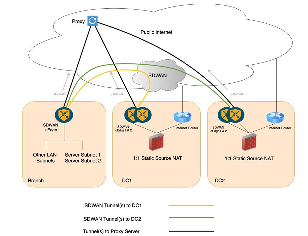
A standard SDWAN deployment with dual DC setup and a branch site has been considered in order to portray this scenario as shown in the next diagram. There can be multiple branches, however, for the sake of simplicity only one has been depicted. The DCs and branch sites communicate over Secure SDWAN Overlay, that is, through the SDWAN Secure IPSec tunnels. In this existing setup both the DCs and Branch site have tunnel(s) to the proxy servers in the service Virtual Routing and Forwarding (VRF) and the default route in the service VRF/Virtual Private Network (VPN) points to this proxy.
This topology setup consists of a Branch Site where two servers subnets, Server Subnet 1 and Server Subnet 2 are hosted. There are two Data centers, where each of the Data center Firewalls perform 1:1 Static Network Address Translation (NAT) in order to allow the respective Branch Server Subnet to be reachable from Internet. In order to be precise, Data center 1 Firewall performs the 1:1 Static NAT for Server Subnet 1 and Data center 2 Firewall performs the same for Server Subnet 2.
Customer Requirement
With the earlier setup in mind the requirement from customer can be as mentioned:
- Public application like MS Teams has to access these servers hosted in Branch. As stated earlier the availability of stateful FWs in the DCs makes the customer request for them to be used instead of direct inbound connection to the Branch site.
- The Server Subnet 1 in the Branch must be reachable via DC1 and the Server Subnet 2 in the Branch must be reachable via DC2 from the Internet.
- No Public IP must be routed within the Customer Network.
- The Branch hosted Server Subnets 1 and 2 are configured with Private IPs and the Private to Public IP translation must happen in the respective DC FWs.
- There must not be any underlay routing changes.

Note: If there are no changes made to traffic flow either in the DC or Branch site, the forward traffic from the internet will go through the DC Firewalls in order to reach the servers at the branch site. On the other hand, the return traffic will directly pass through the Proxy at Branch SDWAN router (using the default route) in order to reach the internet source. This is an asymmetric flow of traffic.

Possible Solutions
There can be two possible solutions for the earlier requirements:
- Custom Traffic Engineering with Centralized Data Policy where traffic blackholes in case of DC LAN link failure.
- Service Insertion with Centralized Data Policy where the traffic does not blackhole in case of DC LAN link failure.
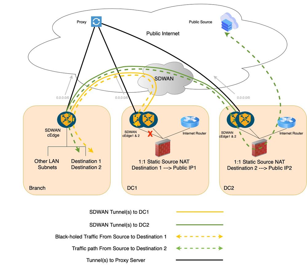
1. Custom Traffic Engineering with Centralized Data Policy
If Custom Traffic Engineering data policies under the Centralized Data policy are considered, one for the branch and another for the DC, the Branch data policy sends the traffic from Branch to the DC using remote-tlocs and the second data policy further route the flow within DC from the cEdge towards the Firewall (FW). But, with the remote-tloc option configured in the Branch, the Branch SDWAN router is unaware of the DC SDWAN Router 1 LAN link failure. That is, if the LAN link at the DC SDWAN Router 1 fails, then, the Branch router is unaware and still forwards that traffic to the DC SDWAN Router 01. Hence the traffic easily Black holes at DC SDWAN Router 1.
Configuration (With Custom Data Policy)
Applied on DC SDWAN Router from-tunnel direction:
data-policy <PolicyName>
vpn-list <VPN_Name>
  sequence 1
     match
      source-data-prefix-list <BranchSiteServerSubnet>
     destination-data-prefix-list <PublicIPSubnet>
     !
     action accept
      set
       next-hop <Firewall_IP>
      !
     !
Applied on Branch SDWAN Router from-service direction:
data-policy <PolicyName>
vpn-list <VPN_Name>
  sequence 1
     match
      source-data-prefix-list <BranchSiteServerSubnet>
     destination-data-prefix-list <PublicIPSubnet>
     !
     action accept
      set
         tloc-list <DC_TLOC_LIST>
      !
     !
  !
  tloc-list <DC_TLOC_LIST>
   tloc <DC cEdge01 System IP> color <primary colour> encap ipsec preference 100
   tloc <DC cEdge02 System IP> color <secondary colour> encap ipsec preference 50
  !
Traffic Flow with Custom Data Policy (DC SDWAN Router 1LAN Link Failure Case)
The traffic blackholes at DC SDWAN Router 1 in case of DC SDWAN Router 1 LAN link failure.
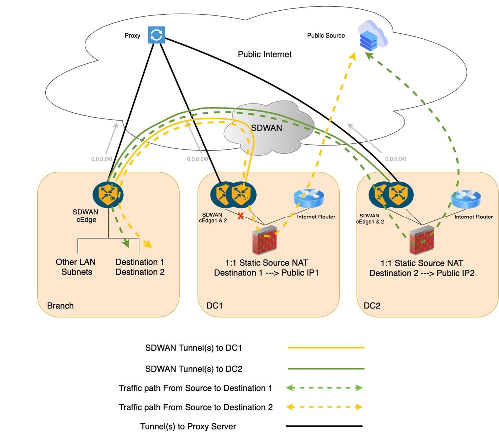
2. Service Insertion with Centralized Data Policy
Cisco SDWAN service chaining is inherently very flexible and fully automated. In a legacy WAN setup. If you have to insert a firewall in the path of specific traffic flow it is typically associated with lots of manual configuration at every hop. In contrast, Cisco SD-WAN service insertion process is as simple as matching interesting traffic with a centralized control or data policy, setting the firewall service as a next hop, and then applying the policy to a target site list via a single Network Configuration Protocol (NETCONF) transaction from the Cisco SDWAN Manager to the Cisco SDWAN Controller.
Here are the steps for inserting a Firewall as a service in our configuration example:
1. Define Firewall as a service on the DC cEdge devices. This can be achieved using VPN feature templates as well as direct login to the devices. The tracking on the service is enabled by default, meaning that if the DC Firewall becomes unreachable from the DC SDWAN primary router cEdge1, the entire service will go down, and the traffic will fallback to the secondary router cEdge2 of DC.
2. Build and apply a Centralized data policy to insert the FW service into the traffic path bi-directionally.
Configuration (With Service Insertion)
Configured on DC SDWAN Routers:
!
sdwan
  service firewall vrf X
  ipv4 address <fw next-hop ip>
!
commit
The earlier configuration at DC SDWAN Routers defines a service of the type 'Firewall' which gets advertised to the Cisco SDWAN Controller. The DC SDWAN router stops advertizing the same when the reachability to the firewall service goes off or the firewall itself goes down.
A service-chaining policy is defined as applied on Branch SDWAN Router from-service direction:
data-policy <PolicyName>
vpn-list <VPN_Name>
  sequence 1
     match
      source-data-prefix-list <BranchSiteServerSubnet>
     destination-data-prefix-list <PublicIPSubnet>
     !
     action accept
      set
       service  FW vpn X tloc-list <DC_TLOC_LIST>
      !
     !
  !
  tloc-list <DC_TLOC_LIST>
   tloc <DC cEdge01 System IP> color <primary colour> encap ipsec preference 100
   tloc <DC cEdge02 System IP> color <secondary colour> encap ipsec preference 50
  !
Traffic Flow with Service Insertion (DC SDWAN Router 1 LAN Link Failure Case)
The traffic fails over to DC SDWAN Router 2 in-case of DC SDWAN Router 1 LAN link failure.
These policy prerequisites or predefined lists are defined on the Cisco Catalyst SDWAN Manager as shown for reference:
lists
  data-prefix-list <BranchSiteServerSubnet>
   ip-prefix <ip/mask>
  !
  data-prefix-list <PublicIPSubnet>
   ip-prefix <ip/mask>
  !
  site-list <BranchSiteList>
   site-id <BranchSiteID>
  !
  !
  tloc-list <DC_TLOC_LIST>
   tloc <DC cEdge01 System IP> color <primary colour> encap ipsec preference 100
   tloc <DC cEdge02 System IP> color <secondary colour> encap ipsec preference 50
  !
  !
  vpn-list <VPN_Name>
   vpn X
  !
  !
Traffic Flow Details for Better Understanding
Outside to Inside Traffic Flow
Internet Source (MS Teams) > DC1 FW (NAT) > DC1 cEdge01 > Branch cEdge01 > Server Subnet 1.
Internet Source (MS Teams) > DC2 FW (NAT) > DC2 cEdge01 > Branch cEdge01 > Server Subnet 2.
For this traffic influence is done in respective hops as follows:
Internet Source (MS Teams) > DC1 FW.
Internet Source (MS Teams) > DC2 FW.
The DC1 and DC2 Advertise respective public IP pool to Internet via the Internet CPE at DCs.
DC1 FW > DC1 cEdge01.
DC2 FW > DC2 cEdge01.
Firewall routing for internal subnet.
DC1 cEdge01 > Branch cEdge01.
DC2 cEdge01 > Branch cEdge01.
Cisco SDWAN Routing via Overlay Management Protocol (OMP) overlay.
Branch cEdge01 > Server Subnet 1.
Branch cEdge01 > Server Subnet 2.
Branch Router routing for Internal Subnet.
Inside to Outside Traffic Flow
Server Subnet 1 > Branch cEdge 01 > DC1 cEdge01 > DC1 FW (NAT) > Internet Source (MS Teams).
Server Subnet 2 > Branch cEdge 01 > DC2 cEdge01 > DC2 FW (NAT) > Internet Source (MS Teams).
For this traffic influence is done in respective hops as follows:
Server Subnet 1 > Branch cEdge 01.
Server Subnet 2 > Branch cEdge 01.
Internal Routing from Server side.
Branch cEdge 01 > DC1 cEdge01.
Branch cEdge 01 > DC2 cEdge01.
Using Centralized Data Policy (Service chaining) to influence traffic path.
DC1 cEdge01 > DC1 FW.
DC2 cEdge01 > DC2 FW.
Using Service Labels in order to influence traffic path from SDWAN cEdge to respective FW at DCs.
DC1 FW (NAT) > Internet Source (MS Teams).
DC2 FW (NAT) > Internet Source (MS Teams).
Private IP Sourced traffic from Server is NAT'ed to egress the FW in order to reach Internet via CPE.
 Feedback