Configure and Verify Active/Active L1 PBR in ACI
Available Languages
Download Options
Bias-Free Language
The documentation set for this product strives to use bias-free language. For the purposes of this documentation set, bias-free is defined as language that does not imply discrimination based on age, disability, gender, racial identity, ethnic identity, sexual orientation, socioeconomic status, and intersectionality. Exceptions may be present in the documentation due to language that is hardcoded in the user interfaces of the product software, language used based on RFP documentation, or language that is used by a referenced third-party product. Learn more about how Cisco is using Inclusive Language.
Introduction
This document describes how to configure and verify Active/Active L1 Service Graph in Application Centric Infrastructure (ACI).
Prerequisites
Requirements
Cisco recommends that you have knowledge of these topics:
- Understanding of how Layer 3 Service Graph works in ACI
- Understanding on how to configure Endpoint policy group, bridge domains and contract in ACI
Components Used
The information in this document is based on these software and hardware versions:
- APIC Version: 5.3(2a)
- Leaf H/W: N9K-C93180YC-FX , N9K-C93180YC-EX
- Leaf S/W: n9000-15.3(2a)
- Leaf Node 101, 102 , 103 ,104
The information in this document was created from the devices in a specific lab environment. All of the devices used in this document started with a cleared (default) configuration. If your network is live, ensure that you understand the potential impact of any command
Topology
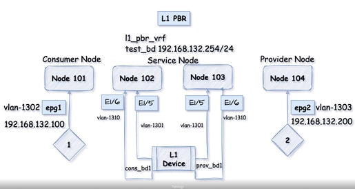
EPG1 and EPG2 configuration is not shown in this document, it must be connfigured before hand and endpoint must be learnt.
1. Validate EPG1 haș endpoint 192.168.132.100 learned (Node 101).

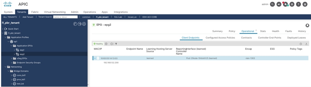
2. Validate EPG2 has endpoint 192.168.132.200 learned (Node 104).
Why is L1 Service Graph needed in ACI?
In Cisco ACI you can insert L4-L7 service device as L3/L2/L1. Layer 3 means that external device is capable of perfoming routing decision to forward traffic whereas Layer 2 means traffic to be solely forwarded on the basis of MAC address. In ACI you can insert an L2 device such as Intrusion Prevention System (IPS)/Transparent Firewall. Now think of a scenario where the device that you are going to redirect the traffic is not capable of taking any forwarding decision, so, in those cases you can deploy L1 Policy-Based Routing (PBR).
Traffic forwarding is same for L3 and L2 PBR cases, the only difference is in case of L3 PBR traffic is redirected to an IP address where as for L1/L2 PBR traffic is redirected to MAC address. These MAC addresses are statically binded to leaf interface for forwarding purpose. You are going to see more on this going further.
For more information on Active/Stanby or Active/Active L1/L2 PBR use cases, refer to the link; PBR White Paper.
About L1 Device
In this deployment model, no VLAN translation is performed on the service device, and both of its interfaces operate on the same VLAN. This approach is commonly known as inline mode or wire mode and is typically used for firewalls and Intrusion Prevention Systems (IPS). It is ideal when the service device is expected to perform security functions without participating in Layer 2 or Layer 3 forwarding.
Active/Active L1 PBR
From ACI release 5.0 onwards, deploying a service graph with L4-L7 devices in an active/active mode is supported. This is achieved by assigning a unique encap to each L4-L7 device interface (concrete interface) and leveraging automatic configuration of ACI of 'Flood in encap' on the hidden service EPG. This hidden service EPG is created by ACI in order to associate the L4-L7 device interface with the service bridge domain.
Administrators do not need to manually configure the hidden service EPG, as ACI automatically enables 'Flood in encap' during the service graph rendering process.
For L1 PBR active-active deployments, port local scope must be configured. This requires placing the consumer and provider cluster interfaces (connectors) of the L4-L7 device in separate physical domains, each with its own VLAN pool, while maintaining the same VLAN range across both domains.
Reference: PBR White Paper.
Configuration for L1 Service Graph
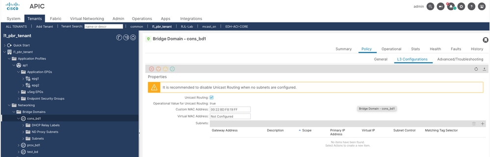
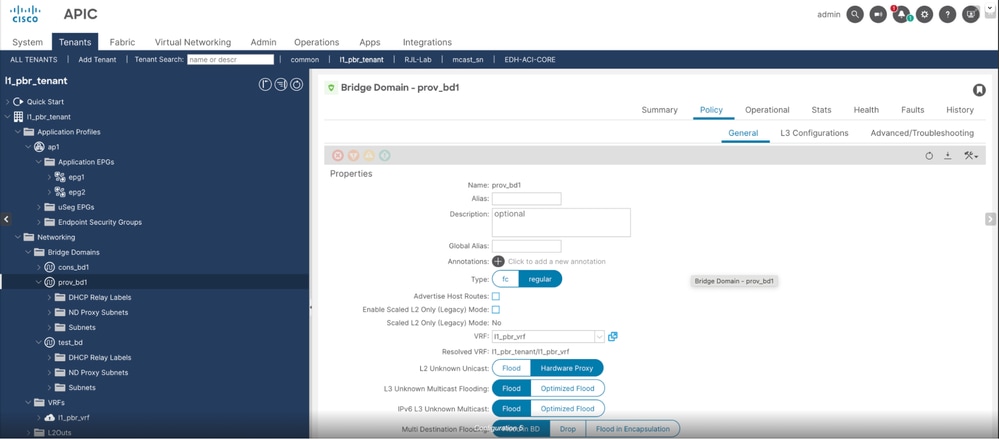
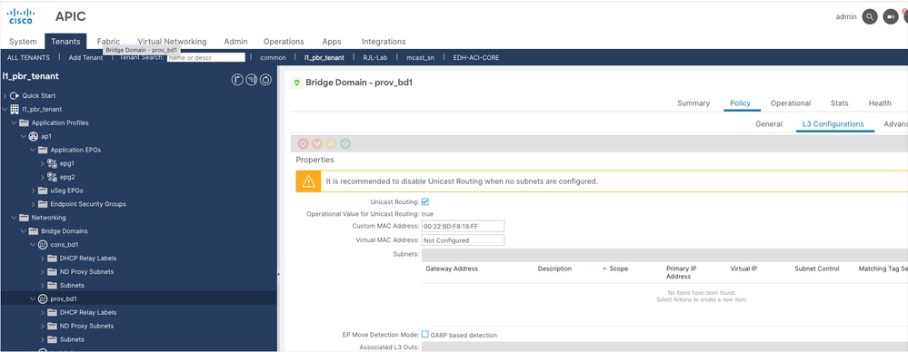
Unicast routing must be enabled, L2 unknown unicast must be set to Hardware proxy and no subnet is required for cons and prov bridge domains.
Step 1. Configure consumer bridge domain named as cons_bd1.
Step 2. Configure provider bridge domain named as prov-bd1.
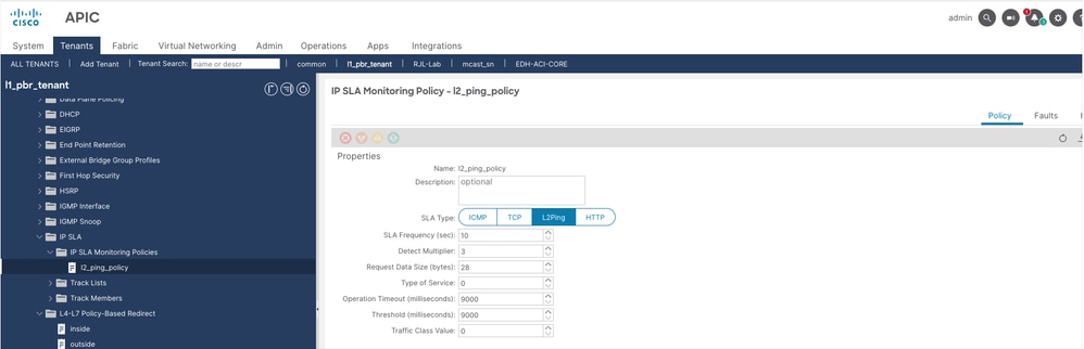
Step 3. Configure IP Service Level Agreement (SLA) Policy with SLA type L2Ping.
Navigate to Tenant > Policies > Protocol > IP SLA > IP SLA Monitoring Policies, then right click and create policy.
Step 4. Configure L4/L7 device.
Navigate to Tenant > Services > Devices, then right click and create L4-L7 device.
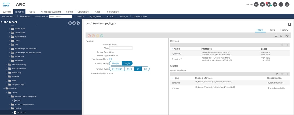

Note: For L1 device, each cluster interface must be in different physical domains for port local scope.
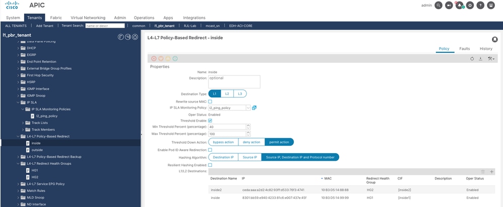
Step 5. Configure L4-L7 Policy based redirect for inside and outside interface.
Navigate to Tenant > Policies > Protocol > L4-L7 Policy based redirect, then right click and create policy.
++ Policy name is inside
++ We have two L1 destinations, one for each L1 device
++ Policy name is outside
++ We have two L1 destinations, one for each L1 device
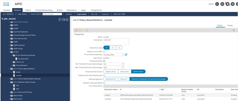
Note: Threshold down action must be same for both L4-L7 redirect policies.
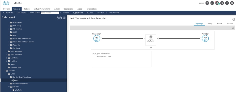
Step 6. Configure Service graph template.
Navigate to Tenant > Services > Service Graph Template, then right click and create L4-L7 Service graph template.
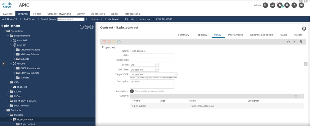
Step 7. Create a contract.
Navigate to Tenant > Contract > Standard, then right click and create contract.
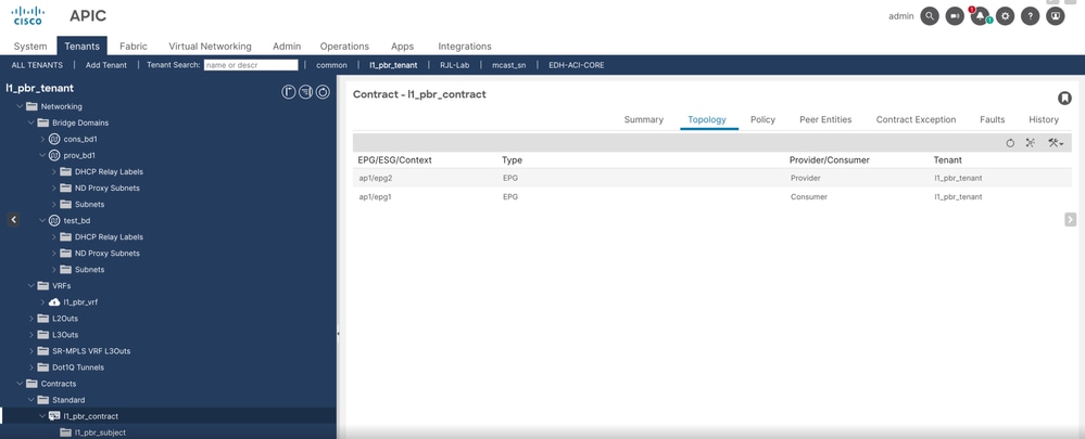
Step 8. Apply the contract as consumer and provider to EPG1 and EPG2 respectively.
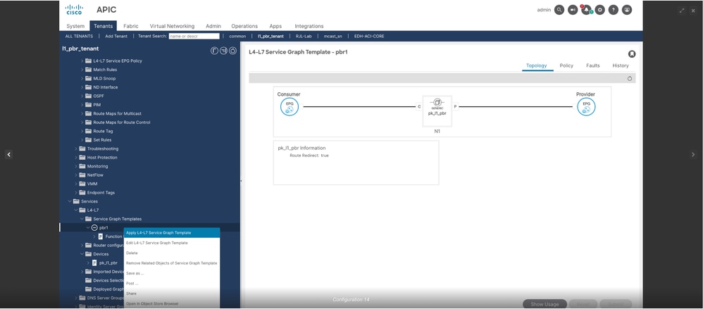
Step 9. Apply L4-L7 service graph template.
Navigate to Tenant > Services > Service Graph Template, then right click PBR1 and apply L4-L7 service graph template.
++ Add consumer and provider EPG
++ Specify contract
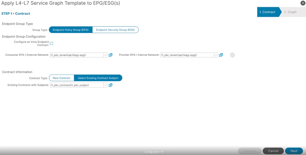
++ click Next
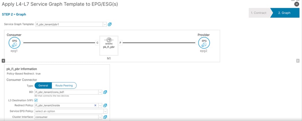
++ Specify consumer connector details
++ Specify provider connector details
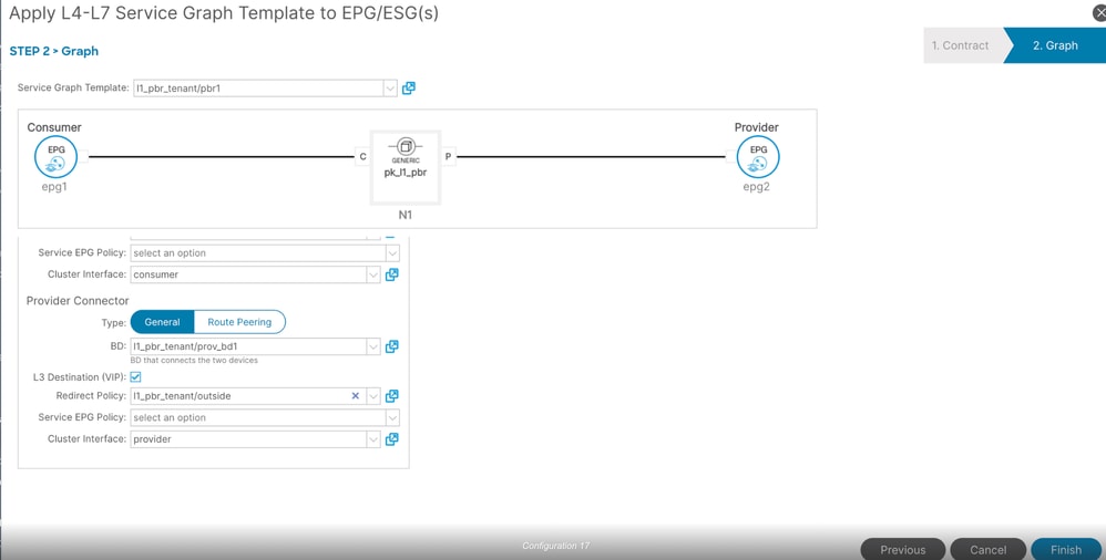
++ Click on finish
Verification for L1 Service Graph on APIC GUI
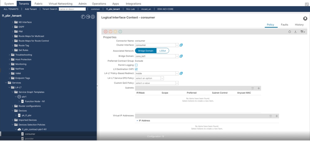
Step 1. Verify the device selection policy created after you apply the service graph template.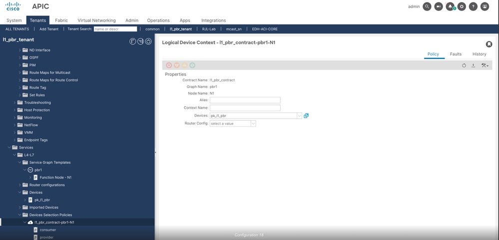
++ Verify consumer connector
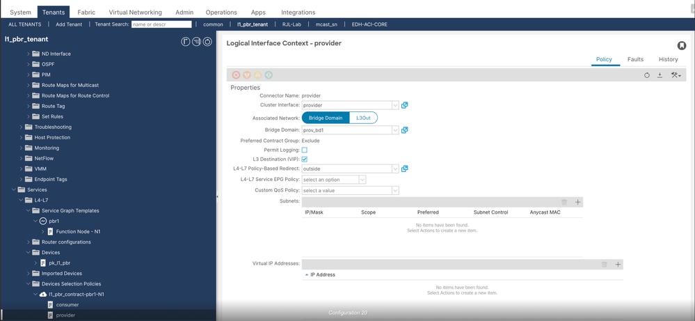
++ Configure provider connector
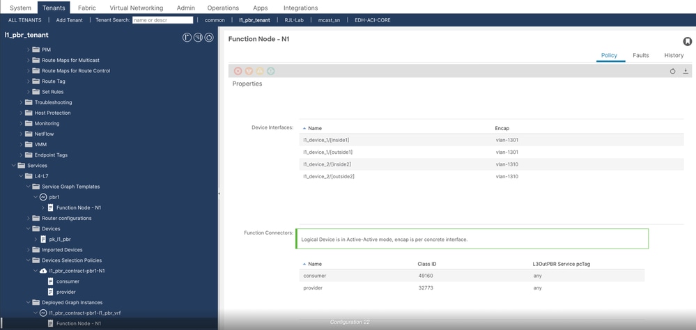
Step 2. Verify Deployed graph instances, there you are going to see an instance, it must be in applied state.
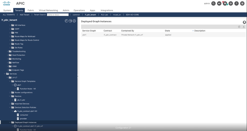
++ Check for device interfaces and fucntion connectors where you are going to see PCTAG associated with service EPG's
Verification for L1 Service Graph on APIC CLI
Step 1. Verify if the service graph is applied on consumer and provider node along with health group status.
apic01# fabric 101,104 show service redir info
----------------------------------------------------------------
Node 101
----------------------------------------------------------------
=======================================================================================================================================
LEGEND
TL: Threshold(Low)  |  TH: Threshold(High) |  HP: HashProfile  |  HG: HealthGrp  | BAC: Backup-Dest |  TRA: Tracking  | RES: Resiliency

=======================================================================================================================================
List of Dest Groups

GrpID Name            destination                                                    HG-name                          BAC  operSt     operStQual      TL   TH   HP   TRAC RES
===== ====            ===========                                                    ==============                   ===  =======    ============    ===  ===  ===  ===  ===

10    destgrp-10      dest-[476f:9be9:5aab:4454:a5d6:8c9e:7017:61eb]-[vxlan-2490369] l1_pbr_tenant::HG2               N    enabled    no-oper-grp     51   100  sym  yes  no
                      dest-[8301:bb59:e940:4233:81c6:e007:437e:45f]-[vxlan-2490369]  l1_pbr_tenant::HG1               N
2     destgrp-2       dest-[2958:ddd3:6eda:4ede:8bb4:1b66:8b19:1eb4]-[vxlan-2490369] l1_pbr_tenant::HG1               N    enabled    no-oper-grp     51   100  sym  yes  no
                      dest-[d438:790d:6fdb:4485:bab7:197d:ef61:9a59]-[vxlan-2490369] l1_pbr_tenant::HG2               N

List of destinations
Name                                                           bdVnid          vMac                 vrf                       operSt     operStQual      HG-name
====                                                           ======          ====                 ====                      =====      =========       =======
dest-[8301:bb59:e940:4233:81c6:e007:437e:45f]-[vxlan-2490369]  vxlan-16252846  10:B3:D5:14:99:99    l1_pbr_tenant:l1_pbr_vrf  enabled    no-oper-dest    l1_pbr_tenant::HG1
dest-[476f:9be9:5aab:4454:a5d6:8c9e:7017:61eb]-[vxlan-2490369] vxlan-16252846  10:B3:D5:14:77:77    l1_pbr_tenant:l1_pbr_vrf  enabled    no-oper-dest    l1_pbr_tenant::HG2
dest-[2958:ddd3:6eda:4ede:8bb4:1b66:8b19:1eb4]-[vxlan-2490369] vxlan-15794150  10:B3:D5:14:66:66    l1_pbr_tenant:l1_pbr_vrf  enabled    no-oper-dest    l1_pbr_tenant::HG1
dest-[d438:790d:6fdb:4485:bab7:197d:ef61:9a59]-[vxlan-2490369] vxlan-15794150  10:B3:D5:14:77:77    l1_pbr_tenant:l1_pbr_vrf  enabled    no-oper-dest    l1_pbr_tenant::HG2

List of Health Groups

HG-Name                                    HG-OperSt  HG-Dest                                                                HG-Dest-OperSt
=======                                    =========  =======                                                                ==============
l1_pbr_tenant::HG1                         enabled    dest-[2958:ddd3:6eda:4ede:8bb4:1b66:8b19:1eb4]-[vxlan-2490369]]        up
                                                      dest-[8301:bb59:e940:4233:81c6:e007:437e:45f]-[vxlan-2490369]]         up
l1_pbr_tenant::HG2                         enabled    dest-[d438:790d:6fdb:4485:bab7:197d:ef61:9a59]-[vxlan-2490369]]        up
                                                      dest-[476f:9be9:5aab:4454:a5d6:8c9e:7017:61eb]-[vxlan-2490369]]        up

----------------------------------------------------------------
Node 104
----------------------------------------------------------------
=======================================================================================================================================
LEGEND
TL: Threshold(Low)  |  TH: Threshold(High) |  HP: HashProfile  |  HG: HealthGrp  | BAC: Backup-Dest |  TRA: Tracking  | RES: Resiliency

=======================================================================================================================================
List of Dest Groups

GrpID Name            destination                                                    HG-name                          BAC  operSt     operStQual      TL   TH   HP   TRAC RES
===== ====            ===========                                                    ==============                   ===  =======    ============    ===  ===  ===  ===  ===
3     destgrp-3       dest-[d438:790d:6fdb:4485:bab7:197d:ef61:9a59]-[vxlan-2490369] l1_pbr_tenant::HG2               N    enabled    no-oper-grp     51   100  sym  yes  no
                      dest-[2958:ddd3:6eda:4ede:8bb4:1b66:8b19:1eb4]-[vxlan-2490369] l1_pbr_tenant::HG1               N
4     destgrp-4       dest-[476f:9be9:5aab:4454:a5d6:8c9e:7017:61eb]-[vxlan-2490369] l1_pbr_tenant::HG2               N    enabled    no-oper-grp     51   100  sym  yes  no
                      dest-[8301:bb59:e940:4233:81c6:e007:437e:45f]-[vxlan-2490369]  l1_pbr_tenant::HG1               N

List of destinations

Name                                                           bdVnid          vMac                 vrf                       operSt     operStQual      HG-name
====                                                           ======          ====                 ====                      =====      =========       =======
dest-[2958:ddd3:6eda:4ede:8bb4:1b66:8b19:1eb4]-[vxlan-2490369] vxlan-15794150  10:B3:D5:14:66:66    l1_pbr_tenant:l1_pbr_vrf  enabled    no-oper-dest    l1_pbr_tenant::HG1
dest-[d438:790d:6fdb:4485:bab7:197d:ef61:9a59]-[vxlan-2490369] vxlan-15794150  10:B3:D5:14:77:77    l1_pbr_tenant:l1_pbr_vrf  enabled    no-oper-dest    l1_pbr_tenant::HG2
dest-[476f:9be9:5aab:4454:a5d6:8c9e:7017:61eb]-[vxlan-2490369] vxlan-16252846  10:B3:D5:14:77:77    l1_pbr_tenant:l1_pbr_vrf  enabled    no-oper-dest    l1_pbr_tenant::HG2
dest-[8301:bb59:e940:4233:81c6:e007:437e:45f]-[vxlan-2490369]  vxlan-16252846  10:B3:D5:14:99:99    l1_pbr_tenant:l1_pbr_vrf  enabled    no-oper-dest    l1_pbr_tenant::HG1

List of Health Groups
HG-Name                                    HG-OperSt  HG-Dest                                                                HG-Dest-OperSt
=======                                    =========  =======                                                                ==============
l1_pbr_tenant::HG1                         enabled    dest-[2958:ddd3:6eda:4ede:8bb4:1b66:8b19:1eb4]-[vxlan-2490369]]        up
                                                      dest-[8301:bb59:e940:4233:81c6:e007:437e:45f]-[vxlan-2490369]]         up
l1_pbr_tenant::HG2                         enabled    dest-[476f:9be9:5aab:4454:a5d6:8c9e:7017:61eb]-[vxlan-2490369]]        up
                                                     dest-[d438:790d:6fdb:4485:bab7:197d:ef61:9a59]-[vxlan-2490369]]        up
Step 2. Verify if the static MAC binding is created on service nodes (102 and 103).
apic01# fabric 102-103 show endpoint vrf l1_pbr_tenant:l1_pbr_vrf
----------------------------------------------------------------
Node 102
----------------------------------------------------------------
Legend:
S - static s - arp L - local O - peer-attached
V - vpc-attached a - local-aged p - peer-aged M - span
B - bounce H - vtep R - peer-attached-rl D - bounce-to-proxy
E - shared-service m - svc-mgr
+-----------------------------------+---------------+-----------------+--------------+-------------+
VLAN/ Encap MAC Address MAC Info/ Interface
Domain VLAN IP Address IP Info
+-----------------------------------+---------------+-----------------+--------------+-------------+
23/l1_pbr_tenant:l1_pbr_vrf vlan-1310 10b3.d514.7777 LS eth1/6
24/l1_pbr_tenant:l1_pbr_vrf vlan-1301 10b3.d514.9999 LS eth1/5

----------------------------------------------------------------
Node 103
----------------------------------------------------------------
Legend:
S - static s - arp L - local O - peer-attached
V - vpc-attached a - local-aged p - peer-aged M - span
B - bounce H - vtep R - peer-attached-rl D - bounce-to-proxy
E - shared-service m - svc-mgr
+-----------------------------------+---------------+-----------------+--------------+-------------+
VLAN/ Encap MAC Address MAC Info/ Interface
Domain VLAN IP Address IP Info
+-----------------------------------+---------------+-----------------+--------------+-------------+
40/l1_pbr_tenant:l1_pbr_vrf vlan-1310 10b3.d514.7777 LS eth1/6
1/l1_pbr_tenant:l1_pbr_vrf vlan-1301 10b3.d514.6666 LS eth1/5
Traffic Validation
1. 2000 ICMP ping packets are being generated from EP1 to EP2 which are going to be redirected to L1 device.
switch1# ping 192.168.132.200 vrf l1_pbr1 count 2000 >>>>> sending 2000 packets
64 bytes from 192.168.132.200: icmp_seq=464 ttl=251 time=0.859 ms
64 bytes from 192.168.132.200: icmp_seq=465 ttl=251 time=0.872 ms
64 bytes from 192.168.132.200: icmp_seq=466 ttl=251 time=0.844 ms
64 bytes from 192.168.132.200: icmp_seq=467 ttl=251 time=0.821 ms
64 bytes from 192.168.132.200: icmp_seq=468 ttl=251 time=0.814 ms
64 bytes from 192.168.132.200: icmp_seq=469 ttl=251 time=0.846 ms
64 bytes from 192.168.132.200: icmp_seq=470 ttl=251 time=0.863 ms
64 bytes from 192.168.132.200: icmp_seq=471 ttl=251 time=0.819 ms
64 bytes from 192.168.132.200: icmp_seq=472 ttl=251 time=0.802 ms
64 bytes from 192.168.132.200: icmp_seq=473 ttl=251 time=0.851 ms
64 bytes from 192.168.132.200: icmp_seq=474 ttl=251 time=0.815 ms
2. Validate interfaces counters on node 102 and 103 which are connected to L1 device.
apic01# fabric 102-103 show interface ethernet 1/5-6 | grep "Node\|Ethernet\|RX\|packets\|TX"
Node 102
Ethernet1/5 is up
Hardware: 100/1000/10000/25000/auto Ethernet, address: 10b3.d5c5.8f25 (bia 10b3.d5c5.8f25)
30 seconds input rate 0 bits/sec, 0 packets/sec
30 seconds output rate 64 bits/sec, 0 packets/sec
RX
2008 unicast packets 2 multicast packets 0 broadcast packets >>>>>2000 packets recieved from L1 device
2010 input packets 213180 bytes
0 jumbo packets 0 storm suppression bytes
TX
2009 unicast packets 1 multicast packets 0 broadcast packets >>>>> 2000 packets transmitted towards L1 device
2010 output packets 213003 bytes
0 jumbo packets
Ethernet1/6 is up
Hardware: 100/1000/10000/25000/auto Ethernet, address: 10b3.d5c5.8f26 (bia 10b3.d5c5.8f26)
30 seconds input rate 0 bits/sec, 0 packets/sec
30 seconds output rate 64 bits/sec, 0 packets/sec
RX
9 unicast packets 2 multicast packets 0 broadcast packets
11 input packets 1286 bytes
0 jumbo packets 0 storm suppression bytes
TX
9 unicast packets 1 multicast packets 0 broadcast packets
10 output packets 1003 bytes
0 jumbo packets

Node 103
Ethernet1/5 is up
Hardware: 100/1000/10000/25000/auto Ethernet, address: a453.0e75.9a85 (bia a453.0e75.9a85)
30 seconds input rate 0 bits/sec, 0 packets/sec
30 seconds output rate 64 bits/sec, 0 packets/sec
RX
2009 unicast packets 1 multicast packets 0 broadcast packets >>>>> 2000 packets recieved from L1 device
2010 input packets 213003 bytes
0 jumbo packets 0 storm suppression bytes
TX
2008 unicast packets 1 multicast packets 0 broadcast packets >>> 2000 packets transmitted towards L1 device
2009 output packets 212897 bytes
0 jumbo packets
Ethernet1/6 is up
Hardware: 100/1000/10000/25000/auto Ethernet, address: a453.0e75.9a86 (bia a453.0e75.9a86)
30 seconds input rate 0 bits/sec, 0 packets/sec
30 seconds output rate 64 bits/sec, 0 packets/sec
RX
9 unicast packets 1 multicast packets 0 broadcast packets
10 input packets 1003 bytes
0 jumbo packets 0 storm suppression bytes
TX
9 unicast packets 1 multicast packets 0 broadcast packets
10 output packets 1003 bytes
0 jumbo packets
Note: Interface counters were cleared on node 102 and 103 before the traffic was tested.
Revision History
| Revision | Publish Date | Comments |
|---|---|---|
1.0 |
25-Mar-2025
|
Initial Release |
Contributed by Cisco Engineers
- Piyush KatariaCisco TAC Engineer
 Feedback
Contact Cisco
- Open a Support Case

- (Requires a Cisco Service Contract)