Redundancy Architecture for Control Plane in Cloud-Native 5G SA Networks White Paper
Available Languages
Bias-Free Language
The documentation set for this product strives to use bias-free language. For the purposes of this documentation set, bias-free is defined as language that does not imply discrimination based on age, disability, gender, racial identity, ethnic identity, sexual orientation, socioeconomic status, and intersectionality. Exceptions may be present in the documentation due to language that is hardcoded in the user interfaces of the product software, language used based on RFP documentation, or language that is used by a referenced third-party product. Learn more about how Cisco is using Inclusive Language.
This technical paper delves into the redundancy mechanisms embedded within the Cisco® Cloud Native Converged Core control plane solution, with a particular focus on implementation of redundancy at every stack layer. The architecture’s design is pivotal in reliability, resilience, load balancing, seamless maintenance, and cyberattack mitigation.
1.1 Importance of Redundancy
The paper outlines several critical reasons for implementing redundancy.
● Minimizing downtime: Ensuring continuous service availability, especially for critical services and emergency Wireless Priority Service (WPS) slices.
● Resilience: Providing robustness against hardware and software failures in a microservices environment.
● Load balancing: Distributing traffic efficiently across Virtual IPs (VIPs) to optimize performance.
● Disaster recovery: Facilitating recovery from disasters and mitigating the impact of security attacks.
● Application Lifecycle Management (LCM): Enabling seamless patch upgrades and maintenance without service disruption.
The paper emphasizes that redundancy in a mobility network is essential for maintaining reliability, service continuity, and resilience, thereby ensuring a robust and dependable network infrastructure.
1.2 Determining Redundancy Levels
Redundancy design is influenced by several factors, which are explained as follows:
● Capital Expenditure (CapEx) for redundant compute: Investment in additional hardware and infrastructure is needed to support redundancy and meet customer requirements.
● Redundancy at every stack layer: Redundancy should be applied at all system layers to ensure optimal compute utilization and minimize downtime.
● Data consistency and integrity: Mechanisms must ensure that all data copies are accurate and synchronized to maintain system reliability.
● Application latency and efficiency: Redundancy should not introduce additional latency; systems must remain efficient and responsive.
● Scalable redundancy solutions: Redundancy designs must scale to handle increasing demands without compromising performance.
● Operational Expenditure (OpEx): Ongoing costs such as power, cooling systems, maintenance of hardware and software, and personnel to maintain should be considered.
In summary, while redundancy is essential for ensuring network reliability and resilience, it comes with a range of challenges that must be carefully managed to achieve the desired benefits without compromising application efficiency or escalating costs.
2. Converged Core Architecture Overview
Throughput requirements have surged, driven by the escalating demand for data from increasingly bandwidth-intensive user equipment. As service providers strive to accommodate this surge, the adoption of Control and User Plane Separation (CUPS) architecture has emerged as a pivotal strategy. By leveraging this architecture, service providers aim to enhance their capacity to meet soaring throughput demands. The CUPS architecture provides keys benefits including independent scaling of the control plane and user plane, flexibility of deploying the control and user planes in different locations (example: the control plane can be centralized and the user plane can be distributed closer to the edge for improved latency and performance), cost efficiency, optimized network management, network slicing support, and improved availability. This decentralized CUPS architecture, however, results in a network landscape characterized by an extensive array of Control-Plane and User-Plane nodes.
To address the proliferation of nodes and the imperative to maintain redundancy for uninterrupted customer service, service providers are increasingly adopting a multi-layered redundancy architecture. As part of the converged core design, redundancy is implemented at multiple potential points of failure to ensure high service availability and to enhance the robustness and dependability of the service provider network.
The converged core architecture over microservices-based infrastructure presents a sophisticated, cloud-native framework that merges the control plane for both fourth-generation and fifth-generation telecommunication networks, simplifying operations by managing a variety of subscribers and use cases through a single core network. Adhering to 3rd Generation Partnership Project (3GPP) standards for 5G New Radio (NR), this solution delineates network functions based on the separation of the Control Plane (CP) and User Plane (UP) to enhance network performance and capabilities. The solution supports the following converged control plane functions. Below is break down of the Control and User Plane functions in Converged core architecture:
2.1 Converged Control Plane Functions
The architecture includes the following key control plane functions:
● The Cisco Session Management Function (SMF) is a critical Control Plane Network Function (NF) within the core network, to perform subscriber session management and user plane programming.
● The solution integrates the 4G Serving Gateway (SGW) and Packet Gateway Control Plane (PGW-C) with the 5G Session Management Function (SMF), combining them into a single deployment within a Kubernetes deployment namespace. This facilitates support for 4G and 5G radio access technology along with the non-3GPP access gateways.
● This Control Plane Architecture allows for the deployment of multiple logical network functions, serving the same or different applications, within the same Kubernetes cluster but under distinct namespaces.
2.2 Converged User Plane Functions
The architecture also encompasses the following user plane functions:
● The 5G User Plane Function (UPF) within the Ultra Cloud Core is responsible for data processing and forwarding. It utilizes Vector Packet Processing (VPP) technology, which is also employed in the Cisco 4G Control and User Plane Separation (CUPS) user plane, ensuring consistent capabilities across 4G and 5G networks.
● The architecture integrates User Plane Function (UPF) and Serving Gateway-Userplane (SGW-U) functionalities into a unified network function.
● It supports concurrent connections for N4 and Sxa interfaces, allowing for the termination of multiple control planes within a single deployment.
● User Plane NFs are deployed as Virtual Machines through the Cisco Smart Install (SMI), ensuring efficient and scalable network operations.
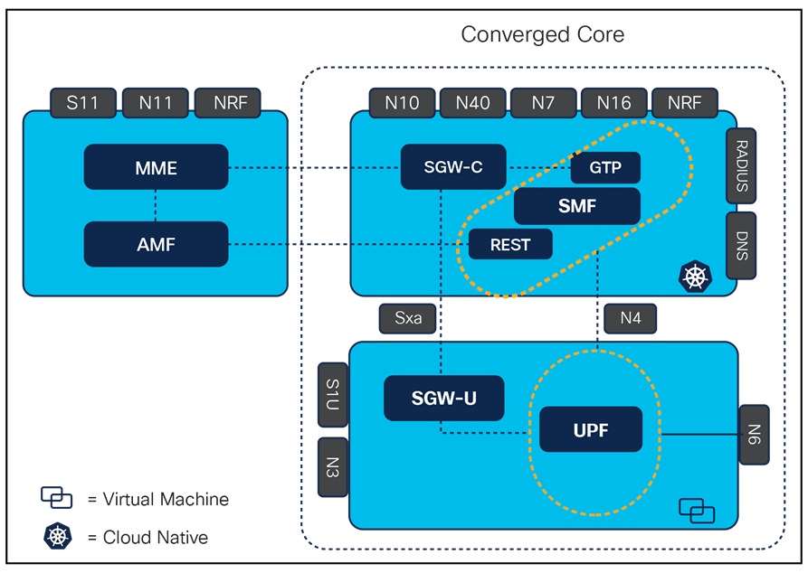
Converged core layout with CP and UP functions
3. Control Plane Redundancy Architecture
To achieve a high degree of redundancy in the control plane architecture of the converged core, a layered redundancy strategy has been implemented. The following is an outline of the various stacks/layers within the Control Plane architecture, each comprising multiple tiers with distinct roles in the overall design. The redundancy architecture for the Control Plane rack/site has been meticulously crafted to guarantee that redundancy is incorporated at every level/tier of the cluster, thereby ensuring high availability.
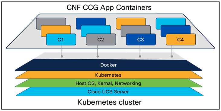
Stack layout of Kubernetes cluster
The following delineates the different redundancy levels incorporated into the Control Plane architecture:
1. Server redundancy via VIP management for K8S containers/PODs and service interfaces
2. Redundancy of physical interfaces using bonded interfaces
3. Redundancy of PCIe connectivity with Top-of-Rack (TOR) leaf switches
4. Redundancy for leaf and spine Top-of-Rack (TOR) switches
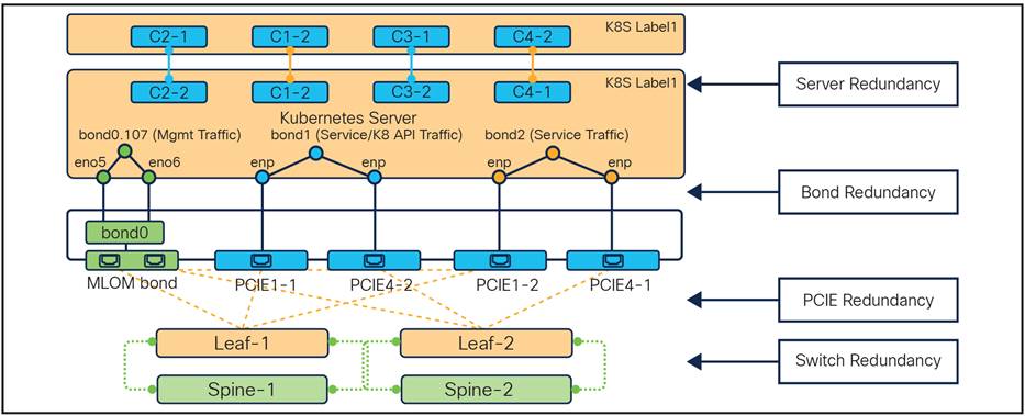
Stack layout of Kubernetes cluster with redundancy
3.1 Server Redundancy
3.1.1 K8S POD Redundancy
The Network Function (NF) for application control is engineered to incorporate redundancy. It is constructed using a microservices architecture on a Kubernetes cluster, embracing the fundamental principles of containerization, which include high availability, scalability, and redundancy.
Replica set deployments manage the service pods that handle application traffic, and these pods are strategically distributed across multiple servers to enhance redundancy and scalability. Pod affinity is established through configurations in the cluster manager and the NF operations center. Pods are linked to nodes using labels, which facilitate the deployment of pods on specific nodes that correspond to the defined key-value pairs. These labels are essential for pods to recognize the nodes they should be deployed on to execute the services. For instance, by setting up the "OAM" layer label with the appropriate key-value pair, the pods will be deployed on nodes that align with the OAM key-value pair.
To link pods with nodes using labels, refer to the sample Service Management Interface (SMI) and cluster deployer configuration provided. An example of this configuration is illustrated in Figure 1, which shows the cluster manager setup for pod deployment with the relevant labels on the Master-3 server.
| maintenance false k8s node-type master k8s ssh-ip 1.1.1.1 k8s sshd-bind-to-ssh-ip true k8s node-ip 1.1.2.1 k8s node-labels smi.cisco.com/node-type oam exit k8s node-labels smi.cisco.com/node-type-2 service-1 exit k8s node-labels smi.cisco.com/node-type-3 session exit |
Sample 1: Cluster manager configuration
Following are the K8 label and keys for POD deployment with redundancy design.
| smi.cisco.com/node-type=oam smi.cisco.com/node-type-1=protocol smi.cisco.com/node-type-2=service smi.cisco.com/node-type-3=session |
Sample 2: Labels key value pairs
In the provided snippet for Master-3, the intention is to deploy pods with the designations "OAM (Operations, Administration and Management)," "SERVICE," and "SESSION." Kubernetes servers that host the application service and require redundancy are set up with shared Kubernetes labels. These common labels are selected to distribute POD replica sets among servers within the cluster to ensure redundancy. Kubernetes handles the life cycle management of PODs automatically, capable of re-launching stateless pods on a different server with the same label or rerouting traffic to an existing replica pod on another server in the case of stateful pods.
Beyond the cluster deployer setup, the Application operations center necessitates the association of labels with the corresponding Application layers, which include "protocol," "service," "OAM," and "session.”
| Stateless (Application and OAM (Operations, Administration, and Maintenance) PODs) k8 label protocol-layer key smi.cisco.com/node-type-1 value proto exit k8 label service-layer key smi.cisco.com/node-type-2 value service exit k8 label oam-layer key smi.cisco.com/node-type value oam
Stateful (CDL slot, index and Kafka PODs) cdl label-config session endpoint key smi.cisco.com/node-type-3 endpoint value session
cdl Kafka replica 2 cdl kafka label-config key smi.cisco.com/node-type-3 cdl kafka label-config value session |
Sample 3. Label and CDL configuration
The following diagram illustrates how Kubernetes labels are aligned with the application requirements to maintain redundancy across the servers to ensure control plane service continuity and high availability.
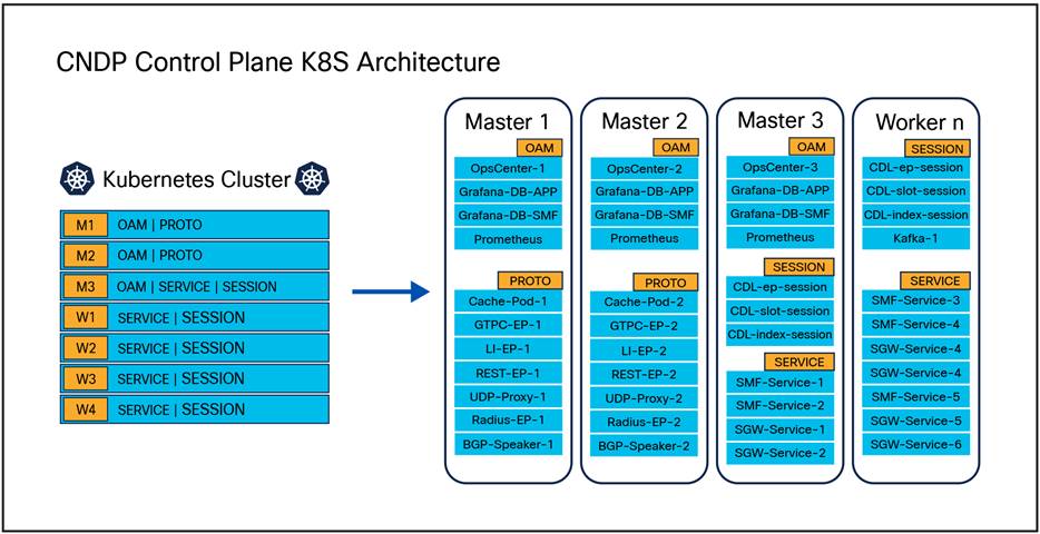
Label layout across servers in cluster
3.1.2 Service VIP Redundancy
There are multiple Cloud Native Deployment Platform (CNDP) networks in the deployment: the service network, the Cisco Integrated Management Controller (CIMC) network, the management network, and the K8S internal network.
● CIMC network: A network where the management ports for most hosts are attached. This network is not connected to any other network.
● K8S internal: High-speed network where all hosts within a cluster can communicate. This network is not connected to any other network.
● Management: Network where a subset of hosts can communicate to external entities for OAM functions.
● Service: Many networks that allow the hosts to communicate with external entities to perform the application message processing.
This document covers “service network” and “K8S internal network” redundancy design details.
Service VIP redundancy is achieved via Keepalived Deamon set, which is used by the application for routing traffic both within the cluster internal network (K8S internal) and to external peer Network Functions (NFs) via “service network.” The service interface networking within the K8S cluster is strategically designed to support two key elements of the architecture:
● Server-level redundancy for the service interfaces (scope of this document)
● To accommodate inter-cluster geographical redundant NFs application traffic post-failovers (separate topic)
To establish server-level redundancy for the service interface, the following are the critical design choices:
● Design choice 1: Implementation of a common “logical bonded VLAN interface” across servers. This interface will be part of the Virtual Router Redundancy Protocol (VRRP) group to host this as VIP.
An example in snippet is S11 GTP virtual IP is designed to float between Master-1 and Master -2 nodes/servers using their corresponding protocol IP 10.10.11.1/28 and 10.10.11.2/28 as the next hop.
Servers should have the same application service interface, for example the Master-1 and Master-2 which serve as Protocol Servers (server with protocol POD label) handling the external communications should have same service interfaces “bd1.s11.1111” as follows:
| nodes master-1 os netplan-additions vlans bd1.s11.1111 dhcp4 false dhcp6 false addresses [ 10.10.11.1/28] id 1111 link bd1 exit exit nodes master-2 os netplan-additions vlans bd1.s11.1111 dhcp4 false dhcp6 false addresses [ 10.10.11.2/28] id 1111 link bd1 |
Sample 4: Netplan sample configuration
● Design choice 2: Associating internal and external application VIP within the same VRRP group to ensure they are consistently hosted on the same server. Refer to Figure 5.
VRRP groups/Virtual IPs are configured as part of the SMI deployment configuration. The same virtual-ip group should be used to ensure that internal and external VIP are always hosted on the same server at any given point of time. The following snippet shows the default VIP affinity is with Master-1 node with priority –100, this configuration allows the keepalived Deamon set to manage VIP with Master-1 node for internal and external applications service VIP.
| virtual-ips gti11s11 check-ports [ 20292 27019] vrrp-interface vlan107 vrrp-router-id 115 check-interface bd2.sgs11.1111 exit check-interface ka2.sgs11.1911 exit check-interface vlan107 exit ipv4-addresses 10.191.1.1 mask 24 broadcast 10.191.1.255 device vlan107 exit ipv4-addresses 10.11.14.0 mask 32 broadcast 10.11.14.0 device ka2.sgs11.1911 exit hosts master-1 priority 100 preempt-delay 20 exit hosts master-2 priority 99 preempt-delay 0 exit |
Sample 5. Virtual-IP Sample configuration
Also in the above configuration, priority configured for the nodes will ensure that in case of a Sunny Day scenario the interface VIP is hosted on the nodes which have higher priority values: Master-1 per the above configuration. Master-2 has the lower priority and will remain as a standby / redundant node that can host the interface vip if the situation arises. This configuration also offers the feasibility of distributing the Service interface VIPs between the nodes to distribute the traffic instead of having all the interface VIP on one node, leading to overload.
Application op-center configuration should have an association of the VIP with the corresponding endpoint and interface for a given cluster instance, as shown below.
| instance instance-id 1 endpoint gtp interface s11 internal-vip 10.191.1.1 cpu max-process 20 echo interval 60 echo retransmission-timeout 5 echo max-retransmissions 4 retransmission timeout 5 max-retry 4 enable-go-encdec true vip-ip 10.11.14.0 vip-interface bd1.s11.1111 exit |
Sample 6. CCGs VIP sample configuration
3.1.3 Advantages
Below are the advantages of the above design choices made:
1. Enhanced redundancy and reliability: By implementing a common logical bonded VLAN interface across servers and using VRRP groups, the design ensures server-level redundancy for service interfaces. This setup allows for seamless failover between nodes, thereby enhancing the reliability and availability of the application.
2. Consistent traffic routing: Associating both internal and external application VIPs within the same VRRP group ensures that they are consistently hosted on the same server. This consistency simplifies traffic routing and management, reducing the complexity of network configurations and potential points of failure.
3. Load distribution: The configuration allows for the distribution of service interface VIPs between nodes. This load balancing prevents any single node from becoming overloaded, thereby optimizing resource utilization and maintaining performance under varying traffic conditions.
4. Simplified management: The use of Keepalived Daemon set for managing VIPs and the strategic design of service interface networking within the Kubernetes (K8S) cluster simplifies the overall management of network configurations. This approach reduces administrative overhead and potential configuration errors.
5. Scalability: The design choices support scalability by allowing additional nodes to be added to the VRRP group without significant reconfiguration. This flexibility is essential for growing applications and adapting to increasing traffic demands.
Overall, these design choices contribute to a robust, reliable, and scalable network architecture that supports high availability and efficient traffic management.
3.1.4 Failure Scenario
Let's examine how the redundancy design described above facilitates traffic transition in the event of a common network failure, such as a single compute failure. The diagram below illustrates a Kubernetes (K8S) cluster in the control plane, detailing the design of PODs and the network across the cluster. For this example, we consider two interfaces supported by the CCG NF application: the N11 and S11 interfaces. The N11 interface is a South Bound interface (SBI) while the S11 interface is User Datagram Protocol (UDP)-based.
The N11 interface communicates with the peer NF (AMF) over the N11 interface, with IPs physically hosted on the interface. The Virtual IP (VIP) is hosted on the server with the highest priority value (100 in this deployment). Depending on the message type and traffic, the interface VIP and interface’s physical IPs are used for inbound and outbound traffic respectively. Conversely, for the S11 interface, which is based on UDP, the S11 VIP handles all inbound and outbound traffic. The VIP hosting is managed by the keepalived service running on the master nodes of the Kubernetes cluster. The VIP and application pods are bound together in the configuration, as explained in the previous section. Similarly, the K8S cluster hosts multiple interfaces and pods on servers, each serving its intended purpose. All protocol pods (responsible for communication with external peers and internal message passing) interact with required application pods, such as services for call processing and CDL for retrieving call data from the database.
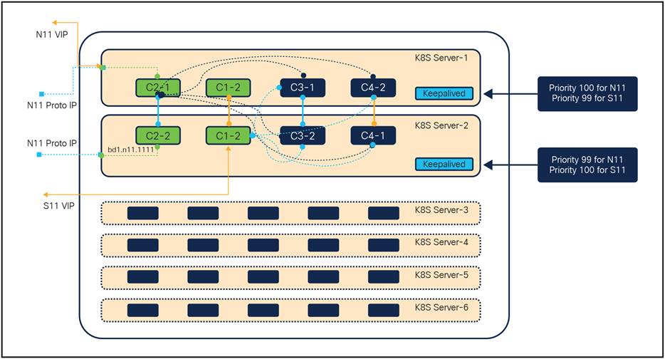
K8S POD and networking layout between the server in K8S cluster
In the event of a critical fault causing a server failure, such as the failure of K8S Server-1 depicted in the diagram below, two types of transitions occur: one at the network layer and the other at the application layer. At the application layer, the server is marked as NotReady at the K8S level, prompting the kube-scheduler to spin up stateless application pods on another server based on CPU and memory availability, as well as the required resources for the application pod. At the network layer, keepalived immediately switches the N11 VIP to K8S Server-2, the second priority server. During this transition, ongoing transactions handled by the application will undergo a retry phase in the network, either by external peer NFs or internal pods, to ensure that subscribers are not impacted.
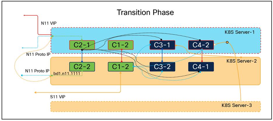
Transition of K8S POD and networking between the server in K8S cluster during failure scenario
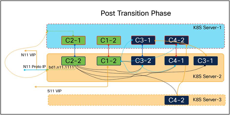
Final state of K8S POD and networking between the server in K8S cluster post- failure scenario
In conclusion, the redundancy design implemented within the Kubernetes (K8S) cluster effectively ensures seamless traffic transition and service continuity in the event of a single compute failure. By leveraging the keepalived service for VIP management and the kube-scheduler for dynamic pod allocation, the system maintains high availability and resilience. The dual-layer transition mechanism—comprising both network and application layers—ensures that critical services remain operational and that ongoing transactions are retried without impacting subscribers. This robust design underscores the importance of redundancy in modern network architectures, providing a reliable framework for handling failures and maintaining uninterrupted service delivery.
3.2 PCIe and Inter-bond Redundancy
The UCS M5 servers are equipped with multiple PCIe slots that accommodate a variety of expansion cards, including Network Interface Cards (NICs), storage controllers, and Graphics Processing Units (GPUs). The PCIe architecture in UCS M5 servers is engineered to meet high-performance computing requirements, making them ideal for demanding applications such as virtualization, databases, big data analytics, and Artificial Intelligence (AI). In the UCS servers utilized for this deployment, there are two NICs, each occupying two slots, resulting in a total of four PCIe slots.
Network bonding, also referred to as bond interfaces, link aggregation, or NIC teaming, is a networking technique that combines multiple network connections into a single logical interface. This method aims to enhance network performance, increase redundancy, and enable load balancing. Within the context of Kubernetes cluster deployment, bond interfaces are configured to ensure redundancy. In this specific deployment scenario, three bond interfaces are created by pairing two network interfaces together. These bonded interfaces are then connected to two distinct Top-of-Rack (TOR) leaf switches via the Modular LOM (MLOM) and PCIe Ethernet interfaces.
The Management traffic is routed over the bond interface 0 (bd0), which was created from two MLOM interfaces that are part of the UCS Server. The MLOM interface slots are connected to the peer nodes, which are TOR leaf switches as depicted below.
All application service traffic is routed over the bonded interfaces created from the PCIe1 and PCIe2 slots. The cross-connection of PCIe interface slots to bond interfaces provides PCIe redundancy. Each bond interface aggregates two PCIe interfaces, with one interface from each PCIe slot in the server. In this design, bond interface 1 (bd1) is deployed with a combination of the enp94s0f0 interface from the first NIC and the enp216s0f1 interface from the second NIC. Bond interface 2 (bd2) is deployed with a combination of the enp94s0f1 interface from the first NIC and the enp216s0f0 interface from the second NIC.
These interfaces are connected to different TOR leaf switches to achieve redundancy at two levels: first, in the event of a hardware fault affecting one of the NICs or PCIe slots, and second, in case of any issues with the cable connecting the server to the leaf switch or a fault at the leaf switch port.
Table 1. PCIe to bond mapping
| Bond / PCIE |
PCIE-1 |
PCIE-2 |
| Bond-1 |
enp94s0f0 |
enp216s0f1 |
| Bond-2 |
enp94s0f1 |
enp216s0f0 |
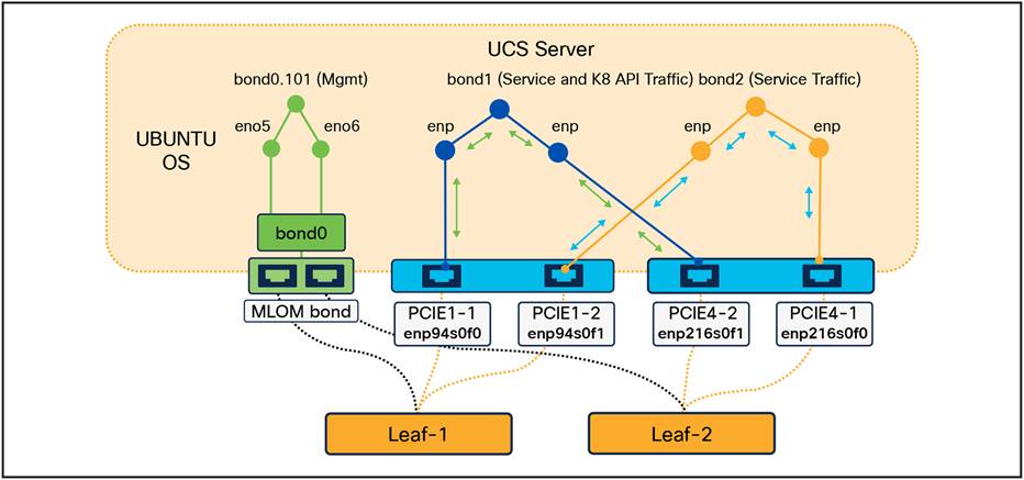
UCS server to TOR switch connectivity via NIC
The above bond design is achieved because of the configuration. Below is the configuration in the SMI deployer with which the bond interfaces can be created by using two different Ethernets.
| node-defaults initial-boot netplan ethernets eno5 dhcp4 false dhcp6 false exit node-defaults initial-boot netplan ethernets eno6 dhcp4 false dhcp6 false exit node-defaults initial-boot netplan ethernets enp216s0f0 dhcp4 false dhcp6 false exit node-defaults initial-boot netplan ethernets enp216s0f1 dhcp4 false dhcp6 false exit node-defaults initial-boot netplan ethernets enp94s0f0 dhcp4 false dhcp6 false exit node-defaults initial-boot netplan ethernets enp94s0f1 dhcp4 false dhcp6 false exit |
| node-defaults initial-boot netplan bonds bd1 dhcp4 false dhcp6 false optional true interfaces [ enp216s0f1 enp94s0f0] parameters mode active backup parameters mii-monitor-interval 100 parameters fail-over-mac-policy active exit node-defaults initial-boot netplan bonds bd2 dhcp4 false dhcp6 false optional true interfaces [ enp216s0f0 enp94s0f1] parameters mode active backup parameters mii-monitor-interval 100 parameters fail-over-mac-policy active exit |
Sample 7. Interface and bond sample configuration
Furthermore, the PCIe interfaces within the control plane architecture serve as hosts for Border Gateway Protocol (BGP) containers, known as bgp-speakers. These containers are crucial for dynamic routing within the Cloud-Native Function (CNF) application, tasked with advertising application service IP addresses for inbound traffic and learning routes for outbound traffic. Below is the sample configuration that needs to be part of the CNF’s BGP configuration to achieve the PCIe redundancy:
| router bgp 65530 learnDefaultRoute false bfd interval 250000 min_rx 1000000 multiplier 10 interface enp216s0f1.2101 bondingInterface enp216s0f1 >>>> PCIe 1-1 bondingInterface enp94s0f1 >>>> PCIe 4-2 neighbor 10.12.101.14 remote-as 64727 fail-over bfd exit
interface enp94s0f0.1101 bondingInterface enp216s0f0 >>>> PCIe 1-2 bondingInterface enp94s0f0 >>>> PCIe 4-1 neighbor 10.11.101.14 remote-as 64727 fail-over bfd exit |
Sample 8. Interface and bond mapping in BGP sample configuration
3.2.1 Common Failures
Below are examples of common network failures and how traffic shifts to redundant paths without impacting the sessions or subscribers hosted in the cluster.
3.2.1.1 Single Slot Failure / Cable Fault
As illustrated in the previous section, the bond interface is constructed with one interface per NIC, and the PCIe slots from each NIC are cross-connected to different Top-of-Rack (TOR) leaf switches. Under normal conditions, traffic is distributed between the two interfaces in the bond, which in turn balances the load across the leaf switches configured to operate in Active-Active mode. However, if one of the interfaces fails due to a hardware fault on either the server or switch side, or due to a cable fault, the traffic seamlessly switches to the redundant path as the interface goes down.
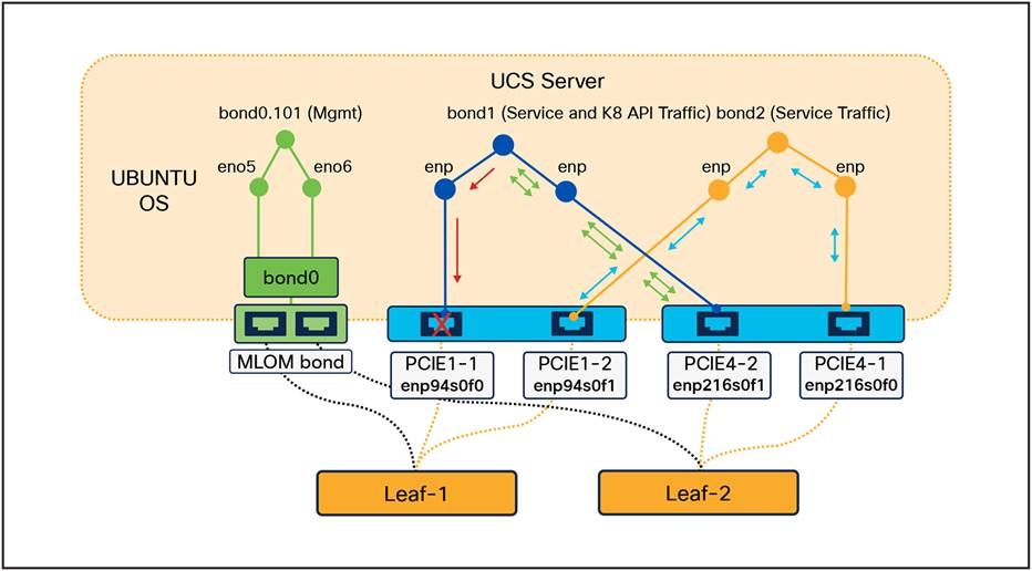
Traffic transition between PCIe slots during single fault
3.2.1.2 Double Fault / NIC Card Failure
As depicted in the diagram below, in a situation where the cables connected from the same NIC are faulty or the NIC itself has a fault, this brings down both the interfaces, creating a double fault situation. In this situation, all the traffic moves seamlessly to the next hop using the other NIC in the UCS where the traffic path is via the second TOR leaf switch.
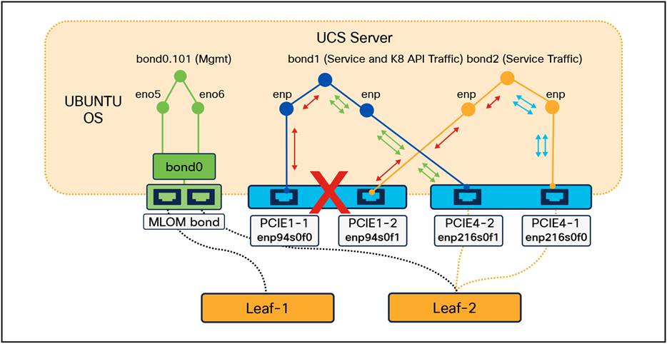
Traffic transition between NICs during double fault
In conclusion, the redundancy mechanisms described effectively mitigate common network failures, ensuring uninterrupted service and maintaining session integrity for subscribers. By employing bond interfaces with cross-connected PCIe slots and leveraging Active-Active configurations for TOR leaf switches, the system can seamlessly handle single slot failures or cable faults. Additionally, in the event of double faults or NIC card failures, the traffic is efficiently rerouted through alternative paths, demonstrating the robustness and resilience of the network architecture. These redundancy strategies are crucial for maintaining high availability and reliability in modern network environments, thereby safeguarding against potential disruptions and ensuring consistent service delivery.
3.3 Top-of-Rack Switches Redundancy
Within the Control Plane architecture, each rack is equipped with three Top-of-Rack (TOR) switches: two leaf switches and one spine switch. The redundancy architecture is designed such that each of the leaf switches is connected not only to the spine switch within its own rack but also to the spine switch in a geographically redundant peer rack associated with the control plane function. This configuration ensures that the leaf and spine switches, which operate in an Active-Active mode, facilitate even traffic distribution among the switches. This arrangement prevents potential overloading or efficiency bottlenecks and, crucially, provides a failover mechanism in the event of switch faults. In such scenarios, the redundant switch seamlessly assumes the traffic load, always guaranteeing the availability of an active traffic path. The connectivity of the TOR switches is illustrated in the diagram below:
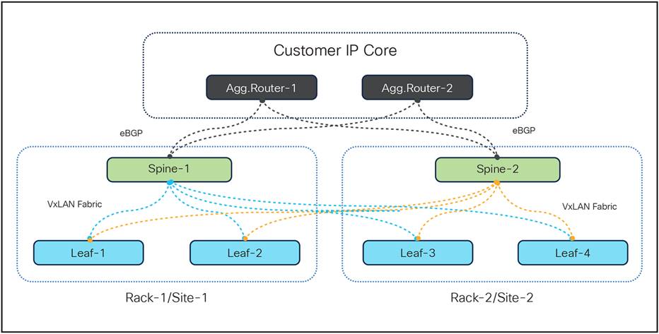
TOR switches (leaf and spine) connectivity
3.3.1 TOR Switches Failures
As illustrated in the diagram above, under normal conditions, traffic is distributed between the two leaf switches, which in turn balances the load across the spine switches configured to operate in Active-Active mode. However, if one of the port-channels fails due to a hardware fault on either of switches, or due to a cable fault, the traffic seamlessly switches to the redundant path as the interface goes down, as illustrated in diagrams below.
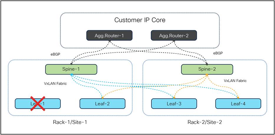
TOR switches (leaf and spine) connectivity during leaf fault
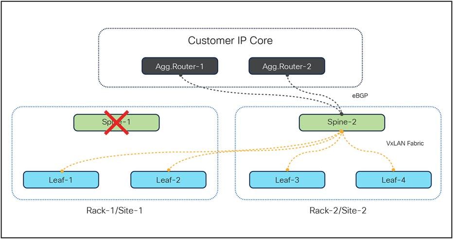
TOR switches (leaf and spine) connectivity during spine fault
In conclusion, the redundancy mechanisms described effectively mitigate common network failures, ensuring uninterrupted service and maintaining session integrity for subscribers. By employing TOR switch interfaces with cross-connected next hop routers and leveraging Active-Active configurations for TOR leaf and spine switches, the system can seamlessly handle single hardware failures or cable faults.
3.4. Geo Redundancy of Control Plane Application Instance
3.4.1 Designing service VIPs for Gr failover scenario
In the 5G framework, the advent of Service-Based Architecture (SBA) within the 5G Core (5GC) has led to the conceptualization of network functions as modular components that offer a range of services and functionalities. A key feature within this modular framework is the support for Network Function (NF) sets as defined by 3GPP. NF sets in the 5G context are essentially clusters of network functions that collaborate to deliver specific services or functionalities within the 5G network architecture. These sets are crafted to enhance various facets of network operations, management, and service provision, thereby contributing to the modular and scalable attributes of 5G networks.
The implementation of NF sets in 5G brings forth considerable benefits, including modularity, scalability, flexibility, and interoperability, which collectively render the network more dynamic and efficient. Nonetheless, this approach also presents certain challenges, such as increased complexity, potential latency issues, security concerns, interoperability difficulties, and associated costs, all of which require meticulous management to fully harness their advantages.
To address these challenges, Cisco has developed a Geo Redundancy solution that is both effective and straightforward in design. This solution can be implemented across the same or separate data centers while preserving the same IP interface network. This design choice eliminates the need for external adjustments or modifications on peer nodes, thereby rendering the Session Management Function (SMF) independent of the support from peer nodes.
3.4.2 Overview
● The Cloud Native Function (CNF) can be geographically deployed to ensure service continuity even if a catastrophic data center failure, such as the loss of a rack having a CNF kubernetes cluster.
● Each SMF instance is registered with the NRF (Network Repository Function) and S11/S5 interfaces for DNS (Domain Naming Service) resolution, easing communication with Mobility Management Entity/Serving Gateway (MME/SGW).
● Local High Availability (HA) redundancy enables an NF instance to achieve rack-level redundancy, in addition to Kubernetes (K8s) cluster-level redundancy within the same data center, or to manage failover within the same K8s cluster.
● This design also enables CDL Redundancy and Replication between the NF instances. The CDL is also equipped with Geo Replication (GR) failover notifications, which can notify the timer expiry of session data and bulk notifications to the currently active site. The CDL uses Border Gateway Protocol (BGP) through App-Infra for the GR failover notifications.
● HA is designed to manage failures of less than 50% of containers, while a GR switchover is started when more than 50% of containers fail, a threshold that is configurable within the SMF.
● The deployment of SMF's GR is designed to be transparent to peer Network Functions (NFs).
● The deployment includes two application instances, each with its own set of interface IPs (Intellectual Property), which must remain consistent across GR deployments for session continuity.
● At any given time, an application instance can be primary on one site/rack and standby on the paired GR site/rack.
● The interface IPs assigned to an application instance are dynamically routed to the primary site of that instance.
● The GR mechanism uses Geo Replication, which ensures uninterrupted service by replicating essential data across remote sites, allowing for a seamless transition during failover scenarios.
● The BGP Speaker POD that is part of the CNF Application handles advertising the right Multi Exit Discriminator (MED) values based on the Role of Application instance, as a lower MED value is always the preferred choice for BGP.
3.4.3 How It Works
a. The SMF can run in a primary/standby redundancy mode, where data is continuously replicated from the primary to the standby instance. The primary instance handles normal operations as depicted in the figure below.
b. For Network Functions (NFs), both instances are active. However, instance-1 and instance-2 are distributed between different racks.
c. In Rack-1/Site-1, both instance-1 and instance-2 are present. Before any trigger event, instance-1 serves as the local primary instance, while instance-2 stays on standby.
d. Similarly, Rack-2/Site-2 has both instance-1 and instance-2. In this location, prior to any trigger event, instance-2 runs as the local primary instance, with instance-1 being on standby.
e. In case, if Rack-1/Site-1 goes down, the traffic moves to Rack-2/Site-2. On Rack-2/Site-2 both the instances, instance-1 and instance-2 acts as primary.
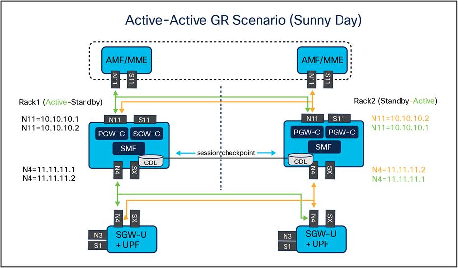
NF to NF Geo Redundancy connectivity in sunny day
● Upon failure of the primary instance, the standby instance assumes the primary role and continues operations as represented in the figure below. For geographical distribution, two primary/standby pairs can be set up, with each site actively processing traffic and the standby serving as a backup for the other site.
● The Geo Redundancy (GR) state of the two mated SMFs is kept via dedicated interface and has Internal-VIP and External-VIP assigned. The Internal-VIP is for Inter-POD communication within the rack and the External-VIP for Inter-Rack Geo pod communication. Configure only on Proto Nodes on L2 Subnet. This is used to communicate across the racks. This node has external connectivity to other racks.
● In an active-active GR deployment scenario, two racks (Rack-1/Site-1 and Rack-2/Site-2) may be situated locally or remotely. These racks process traffic simultaneously, with Network Functions (NFs) communicating with both instance-1 and instance-2.
● In a Geographical Redundancy (GR) deployment, the operational status of the Session Management Function (SMF) Application is shown by the role assigned to each instance. An SMF instance can assume one of the following roles: PRIMARY, STANDBY, or STANDBY_ERROR. The implications of each role are as follows:
a. PRIMARY: When an application instance is appointed as PRIMARY, it is actively processing traffic for that instance.
b. STANDBY: An application instance in the STANDBY role is not currently handling traffic for its specific instance but is prepared to assume control if a failure.
c. STANDBY_ERROR: An application instance in the STANDBY_ERROR role shows a readiness issue, meaning it is not able to manage traffic should its corresponding primary instance encounter problems. During a GR switchover, an SMF instance may transition from PRIMARY to STANDBY_ERROR. This state requires manual intervention to verify the SMF instance's health and ensure it can handle traffic before it can be reset to the STANDBY role. STANDBY_ERROR is the role the SMF is usually set to.
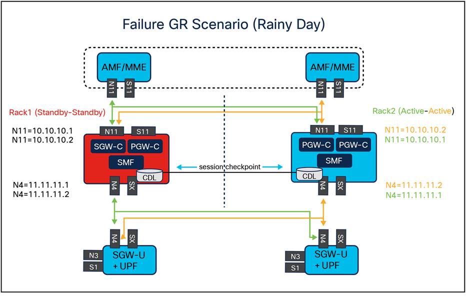
NF to NF Geo Redundancy connectivity in rainy day
3.4.4 Geo Redundancy Conditions
Geographical Redundancy (GR) is designed to start under the following conditions:
● Manual command initiation: GR failover can be manually instigated through specific Command-Line Interface (CLI) instructions that alter the roles of the instances.
● Bidirectional Forwarding Detection (BFD) link failure: GR failover is activated when both BFD links between the connected rack and its corresponding leaf switches fail.
● Local site POD threshold breach: GR failover occurs when the number of failing POD replica-sets exceeds a pre-set threshold percentage.
● Remote site POD compromise detection: If monitoring at a remote site names a failure that surpasses the threshold percentage, the affected POD autonomously assumes the primary role for that instance.
● Remote site role anomaly: Should remote role monitoring reveal that a rack is in a Standby Error state, the system will automatically assign itself as the primary.
● Multiple compute node outages: The GR failover process is triggered if two or more servers are detected to be powered down.
If GR links are down or periodic heartbeat fails, GR triggers are suspended.
This technical paper has thoroughly examined the redundancy mechanisms embedded within Cisco's Cloud Native Converged Core control plane solutionBy implementing a multi-layered redundancy architecture, the solution addresses various potential points of failure, thereby enhancing the robustness and dependability of the network infrastructure.
Key highlights of the redundancy architecture include:
● Server redundancy: Utilizing Kubernetes POD redundancy and Service VIP redundancy to ensure high availability and seamless failover within the cluster
● PCIe redundancy: Implementing bond interfaces and PCIe connectivity to provide fault tolerance against hardware failures and network disruptions
● Top-of-Rack (TOR) switches redundancy: Ensuring active-active traffic distribution and failover capabilities through a well-designed leaf and spine switch architecture
● Geo redundancy: Offering a robust solution for disaster recovery and service continuity across geographically distributed data centers, with mechanisms for automatic failover and role management
The paper underscores the necessity of redundancy in maintaining data consistency, integrity, and application efficiency while managing the challenges associated with increased complexity and potential latency. By adhering to 3GPP standards and leveraging a microservices-based infrastructure, Cisco's solution not only supports the convergence of 4G and 5G networks but also facilitates scalable and flexible network operations.
In conclusion, the redundancy architecture detailed in this paper is pivotal for achieving enhanced service availability, resilience, and performance in cloud-native 5G-SA packet core networks. It ensures that critical services remain uninterrupted, even in the face of hardware failures, software issues, or catastrophic events, thereby providing a reliable and robust network infrastructure for modern telecommunications.
● Sachin Vasanthkumar, Customer Delivery Architect, Cisco Customer Experience
● Uday Kiran Bokam, Customer Delivery Technical Leader, Cisco Customer Experience
● Sujin Anagani, Engineering Technical Leader, MIT-G Engineering
● Rajaneesh Shetty, Principal Architect, Cisco Customer Experience
● Srinivas Rao Karnati, Principal Architect, Cisco Customer Experience
● Gautam Borkar, Technical Marketing Engineering Technical Leader, Mobility TME