Labeling Framework for Telco Cloud Infrastructure White Paper
Available Languages
Bias-Free Language
The documentation set for this product strives to use bias-free language. For the purposes of this documentation set, bias-free is defined as language that does not imply discrimination based on age, disability, gender, racial identity, ethnic identity, sexual orientation, socioeconomic status, and intersectionality. Exceptions may be present in the documentation due to language that is hardcoded in the user interfaces of the product software, language used based on RFP documentation, or language that is used by a referenced third-party product. Learn more about how Cisco is using Inclusive Language.
As organizations increasingly adopt Telco Cloud infrastructure to meet performance, compliance, and data sovereignty requirements, the need for scalable and automated infrastructure lifecycle management becomes critical. In such environments, managing a vast and dynamic set of resources ranging from virtual machines and containers to storage volumes and network components demands a robust and consistent metadata strategy and, in this context, labels play a pivotal role.
Labels as key:value pairs assigned to a resource offer a lightweight yet powerful method for organizing, classifying, and automating resource management. Labels can drive automation, governance, and visibility across the cloud environment. When applied with careful consideration, labels become a foundational mechanism to manage Day 1 and Day 2 operations, such as provisioning and deployment, monitoring, scaling, patching, and decommissioning. Moreover, labels are increasingly being leveraged to strengthen security postures. By integrating label metadata into security policies, organizations can enforce access controls, isolate workloads, and audit activities with greater precision and context-awareness.
This paper explores the definition of a Label Schema and how they can be applied to different domains of a Telco Cloud infrastructure, and also examines a micro-segmentation use case.
2 Telco Cloud infrastructure lifecycle management
Telco Cloud infrastructure lifecycle management refers to the end-to-end process of planning, deploying, operating, maintaining, and eventually decommissioning resources within a Telco Cloud environment. This includes the full spectrum of infrastructure components such as compute, storage, network, orchestration layers, and supporting services whether virtualized, containerized, or bare metal.
Lifecycle management typically spans the following stages:
● Day 0 – Architecture design and capacity planning
● Day 1 – Deployment, provisioning, and initial configuration
● Day 2 – Ongoing operations including monitoring, scaling, policy enforcement, and compliance management, patching and incident response
● Day N – Decommissioning and cleanup
From a design perspective, lifecycle management necessitates modularity, consistency, and automation-readiness. Cloud architects must ensure that infrastructure is designed not just for initial deployment, but for long-term agility and maintainability. This means selecting platforms and tools that support declarative infrastructure-as-code, flexible resource labeling, and seamless integration with orchestration and policy engines.
Labels play a crucial role here by acting as metadata for:
● Automation workflows
● Access control and segmentation
● Cost tracking and optimization
● Compliance auditing
2.1 Role of labels in Telco Cloud
In a Telco Cloud environment, where scalability, multi-tenancy, and operational control are paramount, labels provide a flexible and powerful mechanism to manage complexity. As simple key value pair metadata attached to resources, labels can encode context, ownership, lifecycle state, workload characteristics, and compliance intent— without altering the underlying infrastructure.
Labels serve as the connective tissue between infrastructure state and a, enabling smarter, more context-aware operations across automation, inventory management, and security enforcement.
2.1.1 Labels for automation
Labels empower automation platforms and configuration management tools (e.g., Ansible, Terraform) to dynamically target resources based on criteria rather than static identifiers. Some of the use cases of labels for automation include:
● Self-Service Enablement: Developers can deploy workloads with predefined label schemas that plug directly into operational automation pipelines.
● Lifecycle Awareness: Labels like Environment=Dev or Vendor=X help automate teardown of s tale or temporary resources.
● Dynamic Targeting: Tasks such as patching, scaling, or backups can be scoped using labels like Environment=production, Function=frontend, or Release=9.5.
2.1.2 Labels for inventory and visibility
Traditional inventory models struggle to keep up with the elasticity and abstraction layers of cloud. Labels make it possible to build dynamic, real-time inventories based on business and operational context. Some of the use cases of labels for inventory and visibility include:
● Custom Grouping: Resources can be grouped logically by project, team, application, or service, independent of their physical or virtual topology.
● Search and Filtering: Administrators can quickly locate resources based on combinations of labels (e.g., Function=UPF and Environment=staging).
● Cost Attribution: Usage data can be tied back to labeled entities, enabling chargeback or showback models within internal cost centers.
2.1.3 Labels for security and policy enforcement
In Telco Cloud, where internal segmentation and multi-tenancy are common, labels can be used to inform and enforce fine-grained security policies. Some of the use cases of labels for security and policy enforcement include:
● Policy as Code: Security engines (e.g., Cilium, Calico) can consume labels to define context-aware access and network policies.
● Least Privilege Enforcement: Workloads labeled with sensitivity levels (e.g., Function=PCF) can be automatically placed in hardened zones or governed with stricter Role-Based Access Control (RBAC).
● Incident Response and Forensics: Labels provide forensic context to audit trails—knowing which application, team, or function a compromised resource belonged to accelerates investigation.
A well-defined labeling schema plays a foundational role in managing Telco Cloud infrastructure from instantiation, inventory, lifecycle management, and its day-to-day operations. Labels that are structured as key:value pairs can serve as metadata tags that provide critical contextual information about networking and infrastructure components. When applied consistently, labels enable intelligent automation, fine-grained inventory tracking, routing decisions, and robust policy enforcement across Day 1 (deployment/provisioning) and Day 2 (operations/ maintenance).
In a Telco Cloud, resources can span multiple infrastructure domains such as Compute, Networking, Applications, and Security and can exist in a particular Region, within a single location or multiple locations, in a specific pod or environments, vendors, and service roles. As such the Telco Cloud can be represented with concrete resource as well as logical resources. Without a standardized approach to properly identifying these resources, it becomes difficult to discover, group, or manage at scale. A labeling schema introduces governance by defining consistent way of identification and classification using well defined keys, expected value formats, and usage rules. Using key:value values can be formula-based where a “decoder ring” will be required, or a structured-based approach might offer a more simplified way of identification for humans. Applying the same set of labels across all domains provides a simple way for deployment, avoiding the need to tailor tags for each cloud component.
3.1 Label Definitions for Telco Cloud Infrastructure Resources
Before developing a labeling schema, the corresponding architecture and design of the Telco Cloud must be taken into consideration. At a high level the Regions need to be well-defined, and Point of Presence (PoP) locations must be mapped to their respective regions. The workload types, their placement, and respective requirements should be documented and finally, but very importantly, a Naming Convention must be finalized.
Table 1 show a standardized schema for labels designed to be applied across all Telco Cloud infrastructure.
Table 1. Label Schema for Telco Cloud Infrastructure
| Category |
Key |
Description |
Accepted Pair value |
Value Example |
| Network |
Region |
Geographic location |
[a-z][A-Z] [-] only |
North East, South East, Central, Midwest, Northwest, Southwest |
| PoP |
Physical location |
[a-z][A-Z] [-] only |
NLV, ATL, RDU, BOS, CTL, LAX |
|
| NetworkType |
Network Purpose |
[a-z][A-Z] only |
DataCenter, Core, Management, IT, Mobility, RAN |
|
| InterfaceType |
Type of 3GPP or functional interface |
[a-z][A-Z][0–99] |
Network-OAM, Compute-OAM, RAN-OAM, 5G-OAM, RAN-F1C |
|
| NLRI |
Network Layer Reachability Information |
IPv4, IPv6, Dual Stack |
||
| N-Vendor |
Network Vendor |
[a-z][A-Z] only |
CS, JN, AR |
|
| SeqNumber |
Appearance in Physical location |
[0-99] |
01, 02, 03 |
|
| Environment |
Environment type |
[a-z][A-Z] only |
Dev, Lab, Staging, Prod |
|
| N-ClusterID |
Cluster (where applicable) |
[0–99] |
01, 02, 03 |
|
| N-PodID |
Pod (where applicable) |
[0–99] |
01, 02, 03 |
|
| Compute |
C-Name |
Compute Hostname |
[a-z][A-Z][0–99] |
NE-BOS-01- DL-CP-001-01 |
| C-Vendor |
Compute Vendor |
[a-z][A-Z] |
CS, DL, HP, NV |
|
| C-Virtualization Type |
Virtualization type |
[A-Z][0–99] |
BM, VM, CN, K8 |
|
| C-OS |
Compute Operating System |
[0–99][a-z][A-Z] [-] only |
UB, RH, WN |
|
| C-Port |
Compute MLOM/NIC Port |
[0–99][/] |
1/1, 1/2, 2/1, 2/2 |
|
| C-Release |
Operating System version |
[0–9][a-z][A-Z] [-] [.] only |
24.01,9.5 |
|
| Application |
A-Technology |
Application domain |
[a-z][A-Z] only |
Network, RAN, Packet Core, IMS |
| A-Vendor |
Application Vendor |
[a-z][A-Z] only |
CS, NK, OR |
|
| A-Virtualization |
Application Virtualization type |
PNF, VNF, CNF |
PNF, VNF, CNF |
|
| A-Function |
Network Function |
[a-z][A-Z] only |
AMF, SMF, UPF |
|
| A-Sub-function |
Sub-Network Function |
[a-z][A-Z] only |
MG, OAM, LB |
|
| A-Release |
Application version |
[0–9][a-z][A-Z] [-] [.] only |
24.01 |
|
| A-Owner |
Domain owner |
[a-z][A-Z] only |
PackeSHtCore |
|
| A-Generation |
Architecture release |
[0–99] [.] only |
Gen 1, Gen 2 etc. |
|
| A-Automation |
Automation type used |
[a-z][A-Z] [-] only |
NSO, Ansible, Terraform |
3.1.1 Why a Label Schema Matters
Defining and enforcing a structured labeling schema brings multiple benefits to infrastructure design, deployment, and operations:
● Operational Consistency
A predefined schema ensures that all resources are labeled in a consistent way, regardless of domain, building block, or automation pipeline.
● Automated Workflows
Automation tools (like Ansible, Terraform, or in-house orchestrators) can leverage labels to decipher the intent, make the right decision on what and where a certain component should be provisioned/deployed.
● Routing decisions
Tracking subnets and IP addresses across a large network will no longer be needed. Using labels provides the ability to filter/influence traffic which eliminates the need to update routing policies.
● Security and Compliance
Security policies often rely on labels for scope definition (e.g., “allow traffic from Environment=Prod and Region=North East). A schema ensures accuracy in enforcement boundaries.
● Resource Discovery and Querying
Labels enhance inventory management by enabling filtered searches (e.g., “list all NetworkType=Core devices in Region=Midwest”). This simplifies operations, audits, and troubleshooting.
● Lifecycle Management x
Identification and scheduling upgrades can be significantly simplified by using labels.
● Governance and Auditing
Schemas ensure traceability and make it easy to validate compliance with organizational standards. During audits, labels can be queried to demonstrate policy enforcement and resource ownership.
3.2 Applying Labels to Different Infrastructure Layers
In this example, the Telco Cloud Infrastructure Stack is built using Cisco® Application Centric Infrastructure (Cisco ACI®) along with Cisco IOS®-XR routers and Kubernetes Cluster as shown in Figure 1.
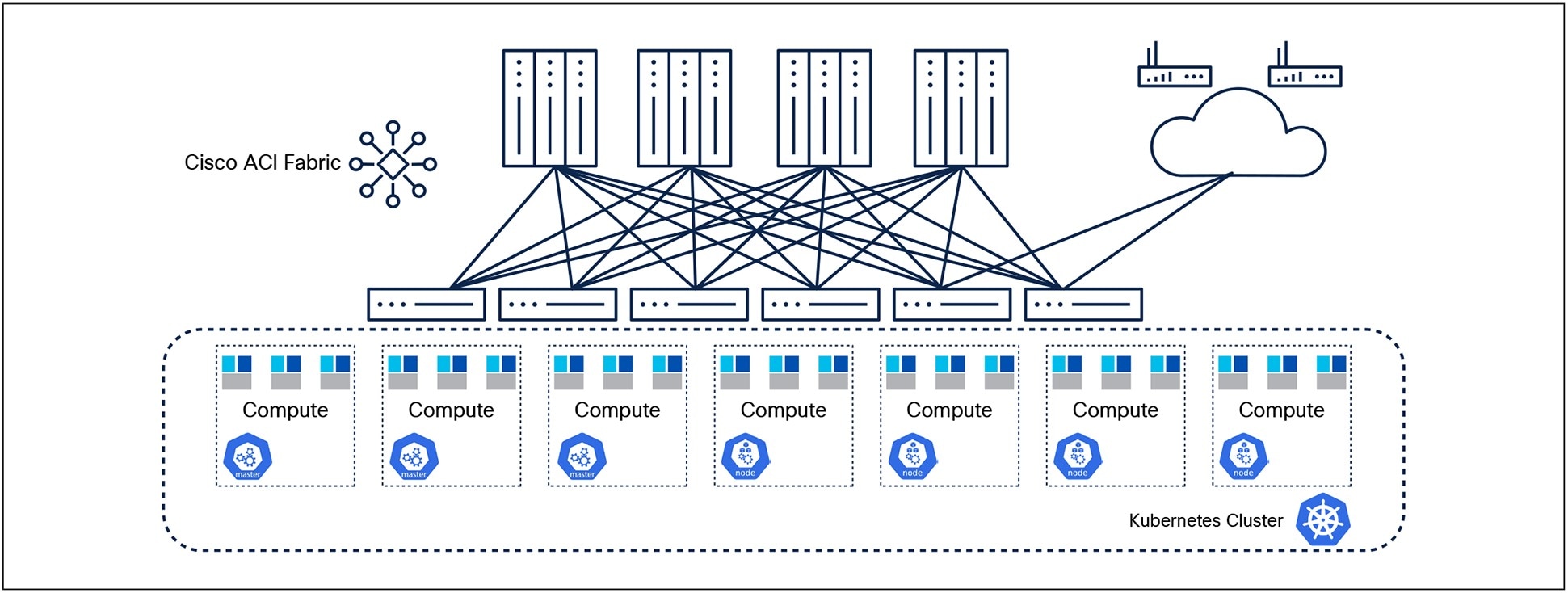
An example of Telco Cloud Infrastructure Stack
Cisco ACI fabric includes Cisco Nexus® 9000 Series Switches with the Application Policy Infrastructure Controller (APIC) to run in the leaf/spine ACI fabric mode. Cisco IOS-XR Routers provide connectivity to the ACI fabric with external networks.
A Kubernetes Cluster is deployed on computes that can either be BareMetal hosts or Virtual machines. The key components of the cluster are:
Master Node (Control Plane):
● Manages the cluster’s state and lifecycle
Worker Nodes:
● Execute workloads (containers) and maintain application health
3.2.1 ACI Labeling structure
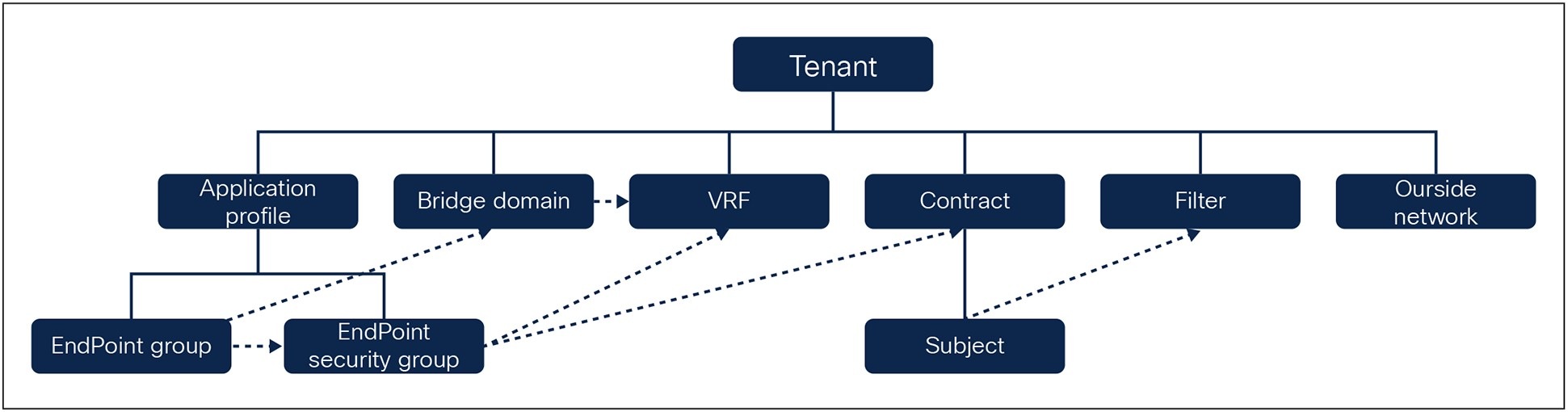
ACI Policy Model for a Tenant
A tenant in Cisco ACI Fabric is a logical container for application policies that enable an administrator to exercise role-based access control. A tenant represents a unit of isolation from a policy perspective, which can be isolated from one another or can share resources. A high-level representation of ACI policy model for a tenant is shown in Figure 2.
The primary elements that the tenant contains are filters, contracts, outside networks, bridge domains, and Virtual Routing and Forwarding (VRF) instances, Application profiles, Endpoint Groups (EPGs), and Endpoint Security Groups. Figure 2 also shows the relationships between the elements of the tenant. The Application Profile contains Endpoint Groups and Endpoint Security Groups. The VRF is associated with bridge domains, and Endpoint groups are associated with bridge domains. And finally the Endpoint Security groups contain Endpoint Security groups and are associated with the VRF.
3.2.1.1 Annotations and Policy Tags in ACI
ACI has native support for labeling or annotating objects shown in Figure 2. Key-Value pairs of metadata can be added to an object as annotations. Note that the Cisco Application Policy Infrastructure Controller (APIC) that manages the ACI Fabric merely stores the annotations with other object data, and they can be queried using Representational State Transfer (REST API). Annotations are provided for the user’s custom purposes, which provides the flexibility to define a common labeling mechanism that can be reused across domains.
Additionally, ACI offers another option to add labels to certain objects in the form of policy tags. Such tags are again user-defined key value pairs, but they are meant for use by ACI features and can be queried using REST API. For example, a policy tag can be used to group endpoints, subnets, and VMs together as one Endpoint Security Group (ESG) using ESG tag selectors.
Using Table 1 as an example and a baseline, Table 2 can be used as a reference where certain labels are “required” for specific ACI resources and where they might not be applicable. This ensures a consistent labeling structure across all domains of infrastructure.
Table 2. Mapping Labels to ACI Resources
| Label Applicability for ACI Resources |
||||||
| Category |
Label Key |
Tenant |
VRF |
Bridge Domain |
EPG/ESG |
Contract |
| Network |
Region |
✓ |
✓ |
✓ |
✓ |
✓ |
| PoP |
✓ |
✓ |
✓ |
✓ |
✓ |
|
| NetworkType |
✓ |
✓ |
✓ |
✓ |
✓ |
|
| InterfaceType |
✓ |
✓ |
✓ |
✓ |
✓ |
|
| NLRI |
✓ |
✓ |
✓ |
✓ |
✓ |
|
| N-Vendor |
✓ |
✓ |
✓ |
✓ |
✓ |
|
| SeqNumber |
✓ |
✓ |
✓ |
✓ |
✓ |
|
| Environment |
✓ |
✓ |
✓ |
✓ |
✓ |
|
| N-ClusterID |
✓ |
✓ |
✓ |
✓ |
✓ |
|
| N-PodID |
N/A |
✓ |
✓ |
✓ |
✓ |
|
| Compute |
C-Name |
N/A |
N/A |
✓ |
✓ |
✓ |
| C-Vendor |
N/A |
N/A |
✓ |
✓ |
✓ |
|
| C-VirtualizationType |
N/A |
N/A |
✓ |
✓ |
✓ |
|
| C-OS |
N/A |
N/A |
✓ |
✓ |
✓ |
|
| C-Port |
N/A |
N/A |
✓ |
✓ |
✓ |
|
| C-Release |
N/A |
N/A |
✓ |
✓ |
✓ |
|
| Application |
A-Technology |
✓ |
✓ |
✓ |
✓ |
✓ |
| A-Vendor |
✓ |
✓ |
✓ |
✓ |
✓ |
|
| A-Virtualization |
N/A |
N/A |
✓ |
✓ |
✓ |
|
| A-Function |
Ö |
Ö |
✓ |
✓ |
✓ |
|
| A-Sub-function |
Ö |
Ö |
✓ |
✓ |
✓ |
|
| A-Release |
N/A |
N/A |
✓ |
✓ |
✓ |
|
| A-Owner |
N/A |
N/A |
✓ |
✓ |
✓ |
|
| A-Generation |
N/A |
N/A |
✓ |
✓ |
✓ |
|
| A-Automation |
N/A |
N/A |
✓ |
✓ |
✓ |
|
3.2.2 K8 Labeling structure
Kubernetes organizes its infrastructure using building blocks that represent the state of applications and the resources they require as shown in Figure 3.
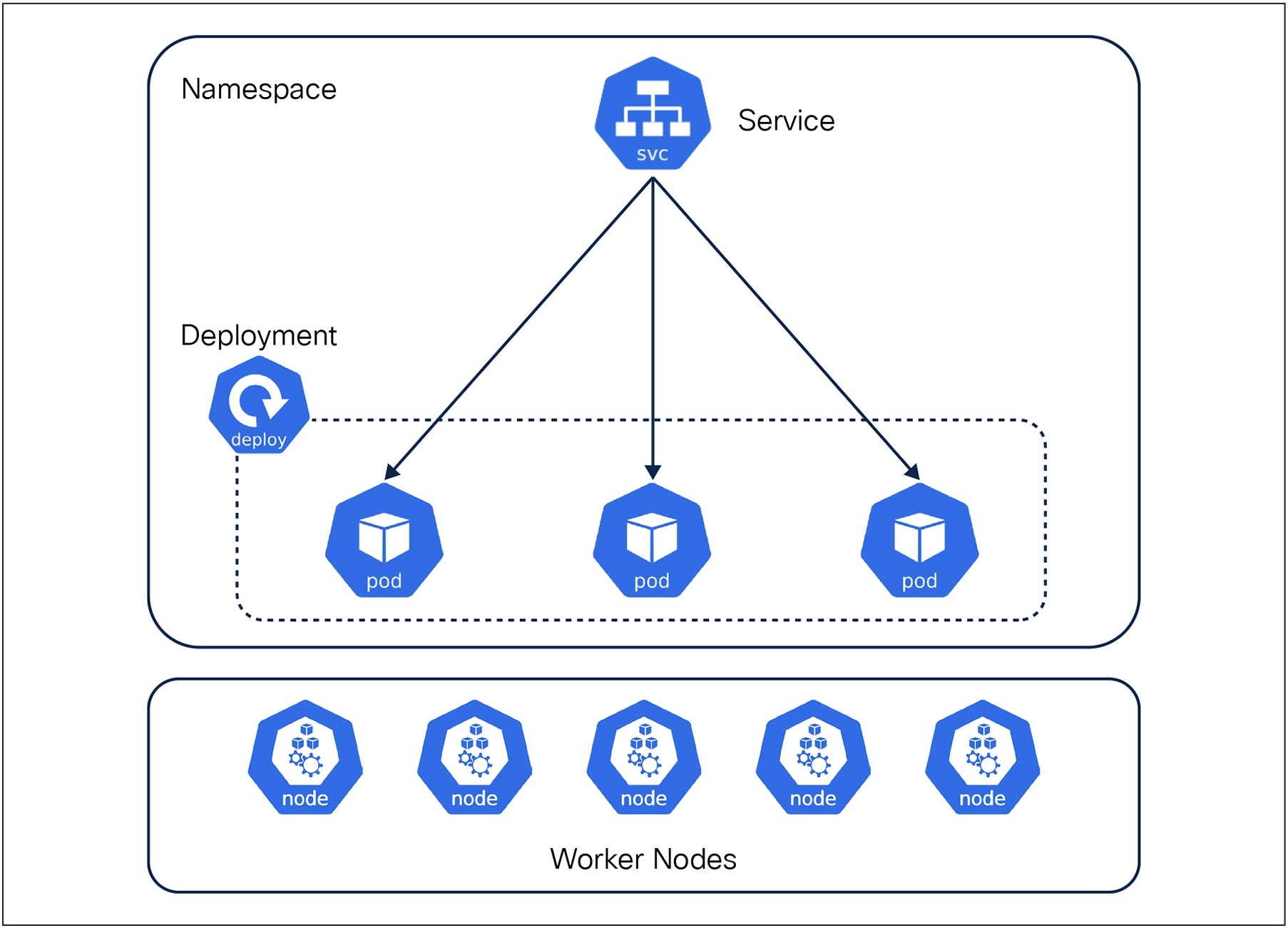
Kubernetes Resource Model Overview
Pod
● Pods are the smallest unit in Kubernetes and represent a single instance of a process in a cluster. A pod can contain one or more containers which share a Network namespace (IP address and ports) and a Storage volume.
Service
● Serves as an abstraction layer that defines a logical set of Pods which provides an IP address and DNS name.
● Services can be exposed using the following:
◦ ClusterIP: Exposes service on a cluster-internal IP
◦ NodePort: Exposes service on each node’s IP at a given port
◦ LoadBalancer: Typically integrates with cloud provider load balancers
◦ ExternalName: Maps the service to an external DNS name
Deployment
● Manages the lifecycle of stateless applications.
● Defines the desired number of Pod replicas and handles:
◦ Scaling
◦ Rolling updates
◦ Rollback
3.2.2.1 Labels in Kubernetes
Labels in Kubernetes are key:value pairs metadata that can be associated to objects such as Pods and namespaces, worker nodes etc. Labels can be attached to objects at the time of creation and modified at any time.
Labels can be used in a similar manner as discussed above using the same proposed structure proposed in Table 1. Additional labels should be considered to address application-specific infrastructure requirements (i.e hardware requirements, virtualization requirements, redundancy, diversity requirements etc.). Table 4 provides an example of labels to be considered.
Using Table 1 as an example and a baseline, Table 3 can be used a reference where certain labels are “required” for specific resources and features and where they might not be applicable. This ensures a consistent labeling structure across all domain infrastructure.
Table 3. Mapping Labels to Kubernetes Resources
| Label Applicability for Kubernetes Resources |
|||||
| Category |
Label Key |
Worker Node |
Namespace |
Deployment |
Service |
| Network |
Region |
✓ |
✓ |
✓ |
✓ |
| POP |
✓ |
✓ |
✓ |
✓ |
|
| NetworkType |
✓ |
✓ |
✓ |
✓ |
|
| InterfaceType |
✓ |
✓ |
✓ |
✓ |
|
| NLRI |
✓ |
✓ |
✓ |
✓ |
|
| N-Vendor |
✓ |
✓ |
✓ |
✓ |
|
| SeqNumber |
✓ |
✓ |
✓ |
✓ |
|
| Environment |
✓ |
✓ |
✓ |
✓ |
|
| N-ClusterID |
✓ |
✓ |
✓ |
✓ |
|
| N-PodID |
✓ |
N/A |
✓ |
✓ |
|
| Compute |
C-Name |
✓ |
N/A |
✓ |
✓ |
| C-Vendor |
✓ |
N/A |
✓ |
✓ |
|
| C-VirtualizationType |
✓ |
N/A |
✓ |
✓ |
|
| C-OS |
✓ |
N/A |
✓ |
✓ |
|
| C-Port |
✓ |
N/A |
✓ |
✓ |
|
| C-Release |
✓ |
N/A |
✓ |
✓ |
|
| Application |
A-Technology |
✓ |
✓ |
✓ |
✓ |
| A-Vendor |
✓ |
✓ |
✓ |
✓ |
|
| A-Virtualization |
✓ |
N/A |
✓ |
✓ |
|
| A-Function |
✓ |
✓ |
✓ |
✓ |
|
| A-Sub-function |
✓ |
✓ |
✓ |
✓ |
|
| A-Release |
✓ |
N/A |
✓ |
✓ |
|
| A-Owner |
✓ |
N/A |
✓ |
✓ |
|
| A-Generation |
✓ |
N/A |
✓ |
✓ |
|
| A-Automation |
✓ |
N/A |
✓ |
✓ |
|
Along with the standardized label schema that is applicable to all the infrastructure domains in Telco Cloud, it is also possible to create additional domain-specific Label schemas. An example of this is provided in Table 4 where additional labels are defined only for the Kubernetes domain.
Table 4. Kubernetes-specific labeling example
| Additional Labels for Kubernetes Resources |
||||||
| Category |
Label Key |
Suggested value |
K8 Cluster |
Worker Node |
Pod |
Namespace |
| Common Name |
Common Name |
OAM | MG | LB |
✓ |
✓ |
✓ |
✓ |
| Hardware |
DPDK |
Yes | No |
✓ |
✓ |
✓ |
N/A |
| SRIOV |
Yes | No |
✓ |
✓ |
✓ |
N/A |
|
| GPU |
Yes | No |
✓ |
✓ |
✓ |
N/A |
|
| Storage |
IDE | SSD | NFS |
✓ |
✓ |
✓ |
N/A |
|
| NUMA |
0 | 1 |
N/A |
✓ |
✓ |
N/A |
|
| Interface |
None | Bond | LACP |
N/A |
✓ |
N/A |
N/A |
|
| Redundancy |
Replica |
<Number of replicas> |
N/A |
N/A |
✓ |
N/A |
| Hardware |
Yes | No |
N/A |
✓ |
✓ |
N/A |
|
| Hugepage |
Yes | No |
N/A |
✓ |
✓ |
N/A |
|
| Virtualization |
CPU Pinning |
Yes | No |
N/A |
✓ |
✓ |
N/A |
| Memory |
Request | Limit | Reserved | Quota | NUMA |
N/A |
✓ |
✓ |
N/A |
|
A few examples of how Kubernetes labels can be used in conjunction with automation to meet application-specific requirements are given below.
Example 1: Deploy a Kubernetes Pod (MG) that does not coexists with its redundant Pod on the same Worker Node
◦ NodeSelector in conjunction with Node Label.
Example 2: Deploy a Kubernetes Pod (MG) on a worker node that supports Data Plane Development Kit (DPDK) and Single Root I/O Virtualization (SR-IOV).
◦ NodeSelector in conjunction with Node Label.
3.2.3 Linux Labeling structure
The Linux operation system is no different than any other resource in the Data Center domain. Most Linux distributions require an application to support labeling a filesystem, directory, or file. An example package is “attr” which provides extended attributes in the form of key:value pair value metadata for system objects and users objects as well. Table 5 can be used as a reference where certain labels are “required” for specific Linux resources and features and where they might not be applicable.
Table 5. Mapping Labels to Linux Resources
| Label Applicability for Compute Resources |
||
| Category |
Label Key |
Linux OS |
| Network |
Region |
✓ |
| POP |
✓ |
|
| NetworkType |
N/A |
|
| InterfaceType |
N/A |
|
| NLRI |
✓ |
|
| N-Vendor |
✓ |
|
| SeqNumber |
✓ |
|
| Environment |
✓ |
|
| N-ClusterID |
N/A |
|
| N-PodID |
✓ |
|
| Compute |
C-Name |
✓ |
| C-Vendor |
✓ |
|
| C-VirtualizationType |
✓ |
|
| C-OS |
✓ |
|
| C-Port |
✓ |
|
| C-Release |
✓ |
|
| Application |
A-Technology |
✓ |
| A-Vendor |
✓ |
|
| A-Virtualization |
✓ |
|
| A-Function |
✓ |
|
| A-Sub-function |
✓ |
|
| A-Release |
✓ |
|
| A-Owner |
✓ |
|
| A-Generation |
✓ |
|
| A-Automation |
✓ |
|
Using Table 5 as a guide, administrators have the ability to create and associate labels as follows in each of the Linux servers.
Assigned a key:value pair POP:NLV to viminfo file;
$attr -s POP -V NLV .viminfo
Output
Attribute “POP” set to a 3 byte value for .viminfo:
NLV
Get key:value pair from a specific file;
$getfattr -d .viminfo
Output
file: .viminfo
user.POP=”NLV”
Search (find) a files associated with a key:value pair;
$find -type f -exec getfattr --name user.MSO -m NLV {} \; 2>/dev/null
Output
file: .viminfo
user.POP=”NLV”
In some deployments, a specific OS release and patch are required to support an application need. In other cases there may be confusion about whether an OS release combination is what is officially certified and whether it is necessary to add labels. Automation can determine whether this OS should be considered for upgrade/patch or not during the Lifecycle management evaluation.
3.2.4 Labeling in Networking infrastructure
Labeling as it’s known in networking typically consists of comments added in configuration lines, descriptions added to Access Control Lists (ACLs), Prefix-lists, route policies etc. Developing a standardized way of adding comments and descriptions provides a great tool in operational efficiency and inventory. While these “labels” are very useful in self-documenting the network, they provide limited usability when it comes to automation or networking simplification in general.
One of the challenges in networking is the ongoing need to change and update. The dynamic nature of applications and strict security requirements demand that we move fast and in a secure manner. One of the common approaches to simplify routing and to “secure the environment” is by identifying and classifying traffic upon ingress into the network, and reacting to the classification as needed from a security prospective or simply to “traffic-engineer.”
Using Boarder Gateway Protocol as an example of how the above can be achieved, specific labels/tags can be added to routes as they ingress the network using BGP communities that are transitive to all BGP peers. Table 6 is an example of how BGP communities can be used as a Labeling mechanism to identify where the routes are being learned, the region that originated the routes the Network is serving, and the interface type.
Table 6. Encoding Labels as BGP Communities
| Encoding Labels as BGP communities |
||
| Label |
Description |
Representation using BGP Communities |
| Peer Type |
Type of BGP peering (ISP, Cloud, SIP, IPX etc.) |
<LocalASN>:<PeerASN> Example: <Partner-1> :<PeerASN> <Upstream-1> :<PeerASN> <Cloud-1>:<PeerASN> |
| PoP |
Physical location |
<LocalASN>:<RPPP> Where R is Region Number PPP is PoP Number Example: Region 1/PoP 1:1001 Region 2/PoP 40: 2040 Region 3/PoP 101: 3101 |
| NetworkType |
Network Purpose |
<LocalASN>:<NetworkType> Where NetworkType is <VRF Route-Target> Example: DataCenter Core Management IT Mobility Metro |
| NetworkInterface |
Type of 3rd Generation Partnership Project (3GPP) or functional interface |
<LocalASN>:<InterfaceType> Where InteraceType is <VRF Route-Target> Example: Network-OAM Compute-OAM RAN-OAM 5G-OAM RAN-SIGNALING RAN-DATA 5G-SINALING 5G-DATA 5G-N2 5G-N3 5G-N4 5G-N6 5G-IMS-UNTRUSTED-ACCESS 5G-IMS-UNTRUSTED-INTERCONNECT 5G-IMS-MEDIA |
At a high level, the approach is to utilize a parent/multi-child policy applied to a BGP peer for simplicity and flexibility.
To implement this, traffic must be classified. In IOS-XR, there are multiple mechanisms available including:
● Advertising source address of route
● BGP AS-path attribute
● BGP community attribute
● Destination Address in the route
Figure 4 shows a configuration example for setting BGP communities for different keys in the label schema.
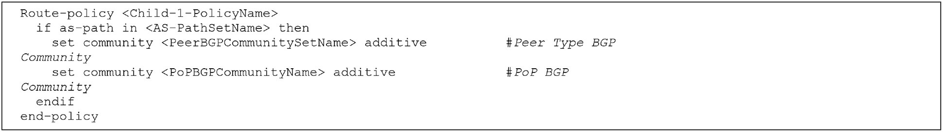
Setting BGP communities for keys in the Label Schema
Subsequently some of the actions that can be taken based on the defined communities are:
● Make routes originating from other PoP less preferred
Route-policy <Child-1-PolicyName>
if community matches-every <PoPBGPCommunitySetName> then
set local-preference 90
endif
end-policy
● Advertise specific interface type to a BGP neighbor
Route-policy <Child-2-PolicyName>
if community matches-every <InterfaceBGPCommunitySetName> then
pass
endif
end-policy
● Advertise specific interface type to BGP neighbor and make alternate routes originating from a remote PoP less preferred
Route-policy <Parent-PolicyName>
apply <Child-2-PolicyName>
apply <Child-1-PolicyName>
end-policy
Using the above approach eliminates the need to add/remove networks from a prefix-list/prefix-sets as traffic is classified/updated, and there are limitless combinations and examples that can be derived from using BGP communities to simplify the network.
3.3 External Label Store
In the previous sections we examined how Labels can be created and stored in domain controllers of Telco Cloud infrastructure or in individual elements like compute nodes or encode the labels in a protocol like Border Gateway Protocol (BGP). To augment or optimize these options, an External label store can be added to the solution to a central location where additional labels or in fact all labels in an environment can be stored, managed, and queried.
Most Enterprises and Service Providers leverage IP Address Management (IPAM) or a Configuration Management Database (CMDB) as an External Label store, since IP addresses and IP subnets are labeled for tracking, identification, and consumption purposes. If IPAM or CMDB are not available, any non-SQL database can store these key:value pairs and can be retrieved with a simple query or script. One such example is MongoDB where a database is created with the name “Labels,” and Collections are created matching key values with specific Documents matching key:value pairs as shown in Figure 5.
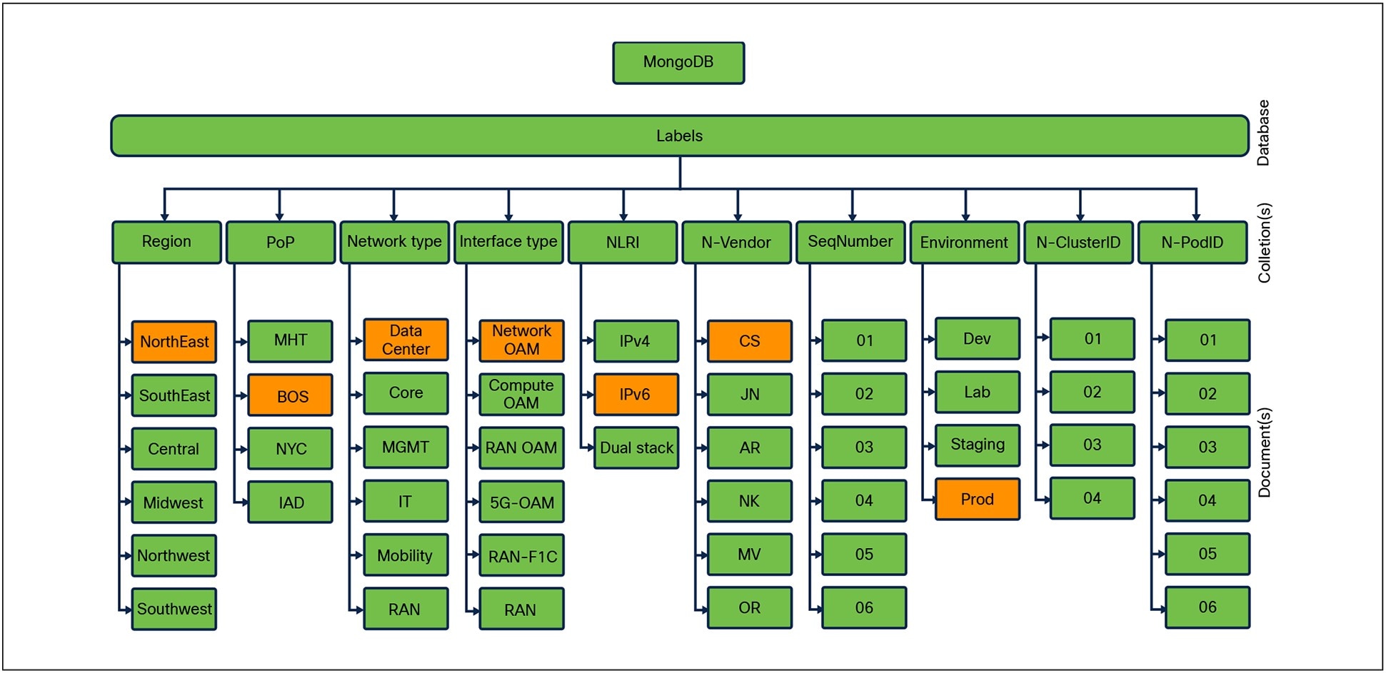
MongoDB Model example
The above figure depicts labels assigned to an APIC. To find an IP address for a specific APIC in a particular Data Center, a query is constructed using given information starting with Region (Norh East), PoP (BOS), Network Type (Network-OAM), NLRI (IPv6), Vendor (CS), and Environment (Prod). The result of the query will return all APICs deployed matching desired criteria, based on the design, the desired APIC can be identified, a subsequent query in IPAM will get the IP address.
Figure 6 shows a simple python script that queries a specific database and returns the list of Documents in a specific collection in the database.
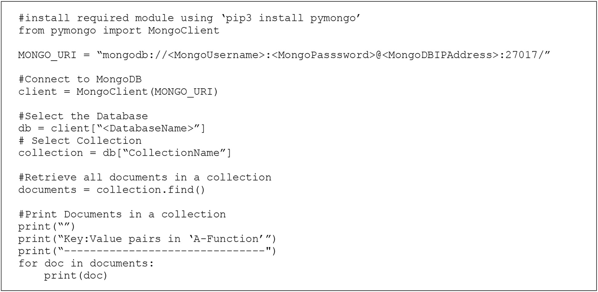
Python Script to query Mongo Database
The output of the query is shown below.
Key:Value pairs in ‘A-Function’
------------------------------
{‘ _ id’: ObjectId(‘6813c6d07ac2904a89a87de8’), ‘A-Function’: ‘UPF’}
{‘ _ id’: ObjectId(‘6813c6d57ac2904a89a87de9’), ‘A-Function’: ‘AMF’}
{‘ _ id’: ObjectId(‘6813c6da7ac2904a89a87dea’), ‘A-Function’: ‘SMF’}
{‘ _ id’: ObjectId(‘6813c6e57ac2904a89a87deb’), ‘A-Function’: ‘DU’}
{‘ _ id’: ObjectId(‘6813c6ec7ac2904a89a87dec’), ‘A-Function’: ‘CU’}
Table 7 summarizes how labels can help solve some of the challenges that are seen in a Telco Cloud environment
Table 7. High-level summary of challenges solved by using Labels
| Challenge |
How Labels Solve It |
| Ephemeral Workloads (e.g., containers) |
Labels follow the workload identity, not the IP, making dynamic environments secure. |
| Policy Sprawl and Complexity |
Labels allow reusable policies, reducing rule duplication. |
| Multi-Tenant Environments |
Labeling by tenant, namespace, or environment enables precise policy boundaries. |
| Inconsistent Enforcement |
Unified label schema ensures consistent policy enforcement across Software-Defined Network (SDN), Kubernetes, and Layer 7. |
| Visibility and Troubleshooting |
Labels improve observability by enabling policy tracing based on application identity. |
| Scalability Limits of IP-Based Rules |
Labels abstract away the need for maintaining massive IP lists or ACLs. |
Let us take the use case of micro-segmentation and examine how labels can play a role in controlling security policy across different domains of Telco Cloud infrastructure.
4.1 Micro-segmentation Policies using Labels
The primary goal of micro-segmentation is to reduce the attack surface by minimizing the possibility of lateral movement in the event of a security breach. SDN technologies enable a new approach, by allowing degrees of flexibility and automation, making micro-segmentation a distinct possibility.
Labels are a fundamental enabler for scalable, intent-driven micro-segmentation because they abstract security controls away from static constructs (like IP addresses or VLANs) and anchor them to dynamic, meaningful identities (like app, environment, or tier). Without Labels, the challenges that come up are:
● Static IP-based firewall rules, IP tables, Contracts, and Container Networking Interface (CNI) policies that break with every pod restart.
● Manual updates to security groups or ACLs across domains.
● Poor alignment between application teams and security teams.
● Limited intent-to-policy automation mapping.
4.1.1 Seamless Cross-Layer Integration
Labels provide a common language across:
● Kubernetes (pod selectors, namespaces)
● SDN/Fabric (e.g., Cisco ACI EPGs, contracts)
● Identity and Access Management (IAM) systems (identity-to-label mapping for zero trust)
This enables multi-layered micro-segmentation that is consistent and manageable.
4.1.2 Identity-Based Policy Enforcement
Instead of writing policies based on ephemeral IPs or manual groupings, labels provide the ability to write rules like:
“Allow A-Function=UPF in Environment=prod to talk to A-Function =backend in Environment =prod.”
This makes policies portable, declarative, and aligned with application intent, not infrastructure wiring.
4.1.3 Dynamic Policy Binding
When a new pod, VM, or endpoint is instantiated with matching labels, the corresponding security policies are automatically applied—eliminating the need for manual rule updates.
Example: A new pod with A-Function = UPF automatically receives backend-specific policies via Kubernetes Network Policy or Cisco ACI EPG contract mapping.
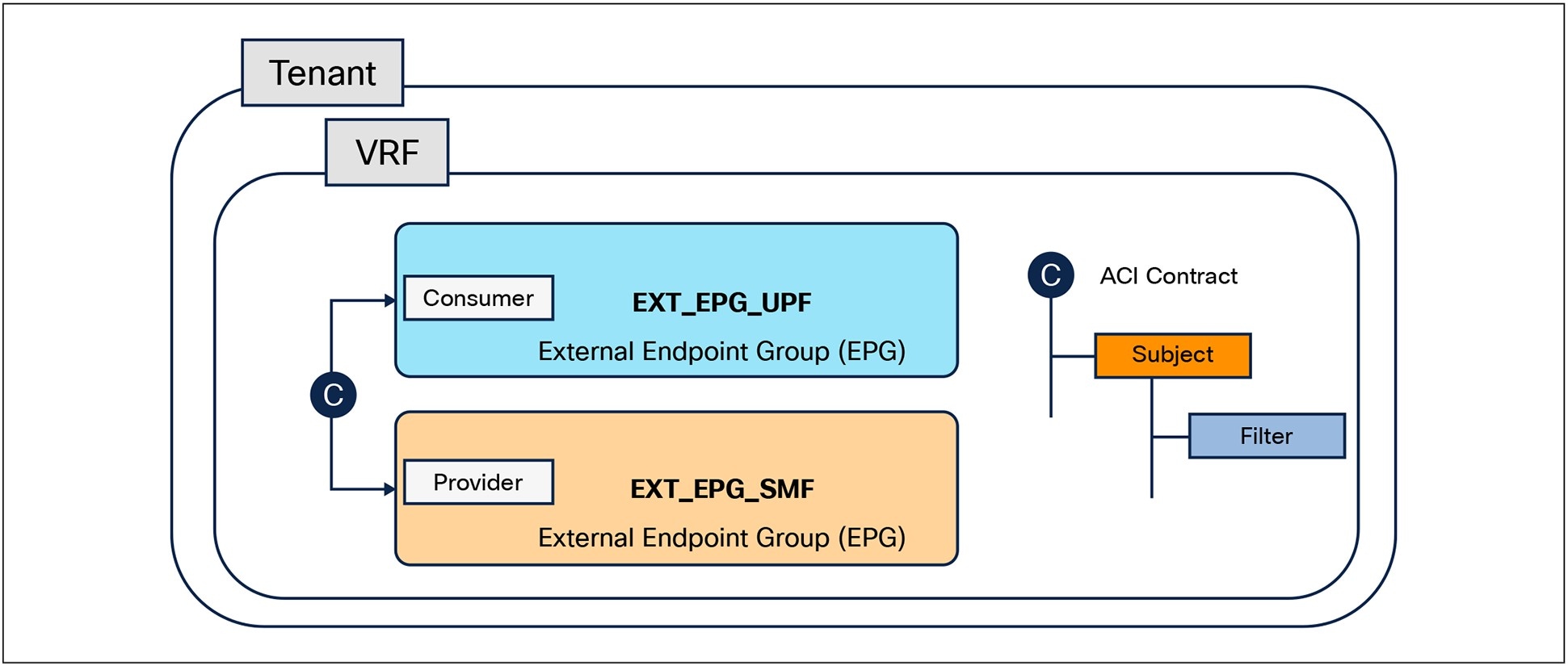
4.1.4 Illustration with a security intent and its Enforcement
The intent is to create a security policy for two applications that are deployed in a specified region and PoP. The policy will define how the applications communicate with each other. When the Security Admin declares the intent, specific requirements such as Layer 4 protocol, Layer 4 port-numbers, and the consumer-provider relationship between the two applications are captured. Figure 7 shows a high-level diagram of where the applications are deployed and the intent of the Security Admin.
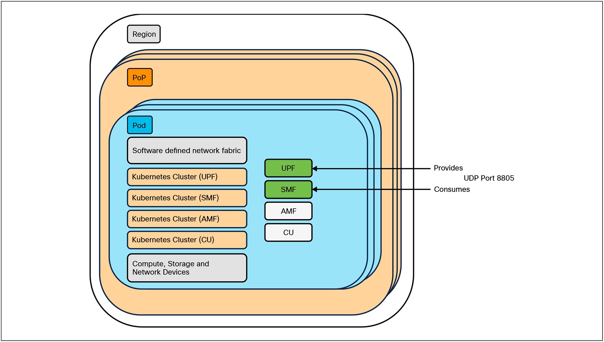
High-Level Intent for Micro-segmentation Policy
With this high-level information, the automation engine needs to derive information about the infrastructure resources that need to be modified or created. Note that in this document, the micro-segmentation design and its implementation are not covered.
As depicted in Figure 8, a lookup in the External Label store would yield information about the APIC Controller that is managing the policies in the ACI Pod and the Kubernetes Cluster where the application is deployed. This will further enable querying the APIC and Kubernetes controller to retrieve the labels that are managed in that domain.
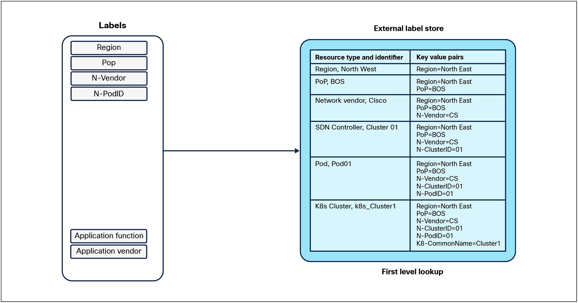
Label lookup in External Label store
As depicted in Figure 9 a query to fetch the labels in the corresponding APIC Controller will provide information on the Endpoint Groups that represent the applications in the ACI Pod.
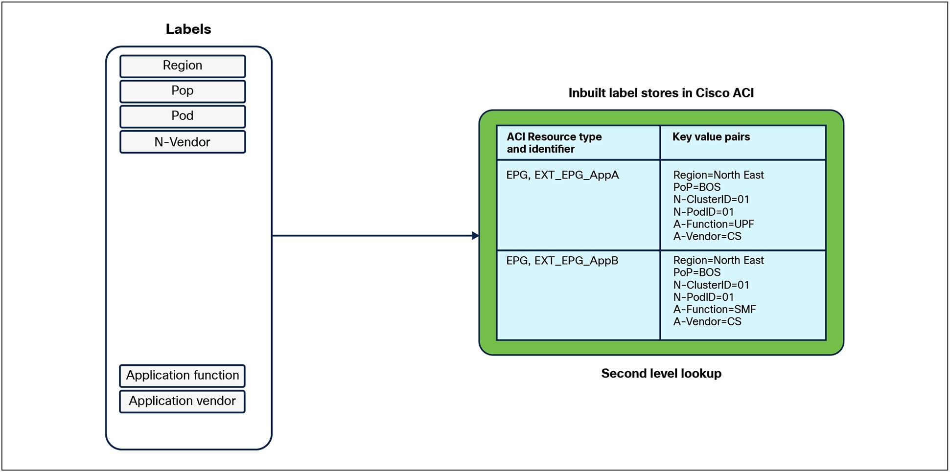
Label lookup in the Cisco APIC SDN Controller
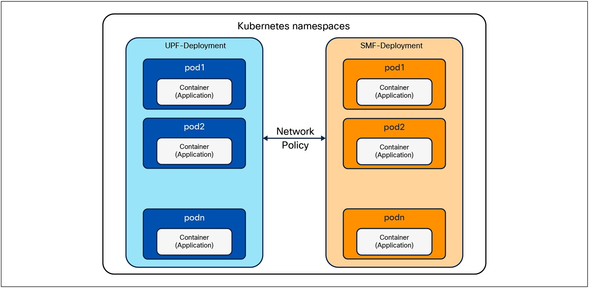
Similarly, as depicted in Figure 10, the Namespace and deployments represent the applications in the Kubernetes cluster and can be obtained using the label information.
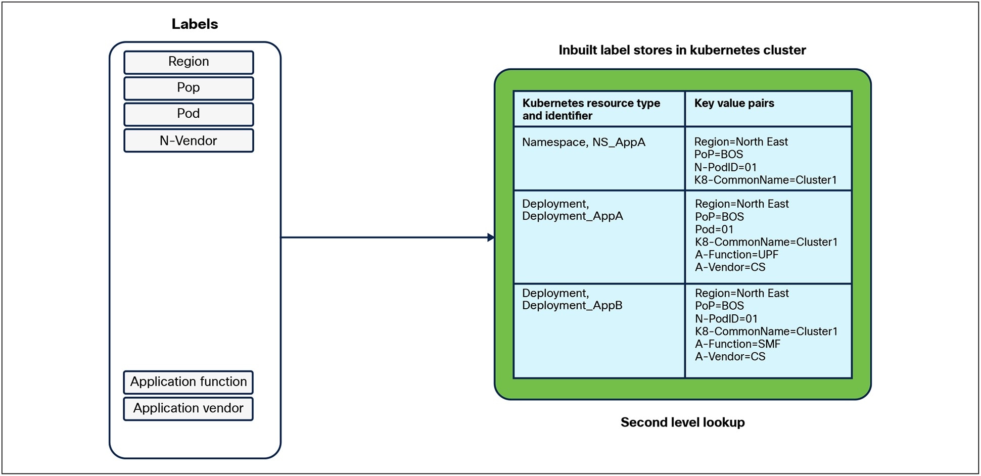
Label lookup in the Kubernetes Cluster
4.1.4.1 Creating ACI contracts
The Endpoint Groups (EPGs) for the corresponding applications are already defined and annotated in the APIC Controller as shown in Figure 11, but it should be noted that not all the annotations are shown for brevity. The annotations can be queried using an API call to fetch the underlying resource information about the EPGs, such as the distinguished name of that resource or ACI object, the type of the resource, and the ACI Tenant Name.
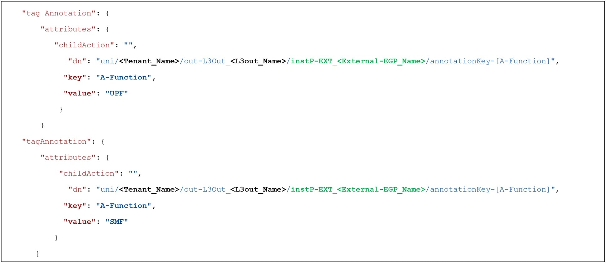
Labels associated with ACI Endpoint Groups
Intended ACI Policy
4.1.4.2 Creating Kubernetes Network Policy
The labels for the corresponding applications are already defined and tagged in the Kubernetes Deployment policies as shown in Figure 13, but it should be noted that not all the labels are shown for brevity.

Labels associated with Kubernetes Deployment
Figure 14 and Figure 15 shows the intended Kubernetes network Policy between the applications.
Intended Kubernetes Network Policy
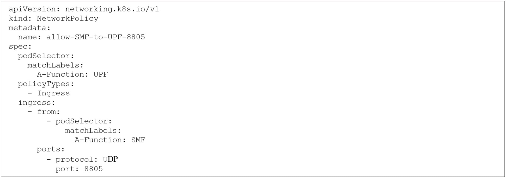
Code for Intended Kubernetes Network Policy
5 Leveraging Label-based framework with GenAI
A well-designed labeling schema encodes structured metadata for resources like compute, network, and storage. This metadata includes attributes such as:
● Region, Data Center.
● Function, Environment, Release.
● Node Role , Network Tier, Security Domain.
In essence, Labels that are created for different resources in the Telco Cloud infrastructure serve as a semantic overlay that Large Language Models (LLMs) and agents can use to understand and reason about infrastructure. A few of the use cases where Label data can be used in conjunction with GenAI and LLMs are listed in Table 8.
Table 8. GenAI use cases using Label Data
| Use Case |
Description |
| Security Automation |
Auto-generate network policies between tiers based on label-defined zones |
| Inventory Management |
Generate reports of infra grouped by labels like release, region, or owner |
| Deployment Planning |
AI agents decide where to place workloads based on label-defined affinities |
| Root Cause Analysis |
Graph RAG explores connected nodes and infra tiers to isolate fault zones |
5.1 Label Data
As noted earlier, some of the domains of Telco Cloud infrastructure support adding labels to resources natively while others don’t. Further within that domain, adding labels may not be supported for all resources or objects. As a result, an external label store is leveraged to supplement the inbuilt label stores and is shown in Figure 16.
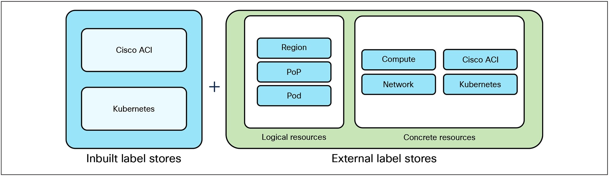
Augmenting Inbuilt label stores with External Label Store
5.2 Relationships and Graph
Having a relationship map between the different resources of the Telco Cloud infrastructure and the associated label data for each of the resources can serve as a powerful combination to realize different use cases. If the relationship can be captured in a graph, it can be used to augment interactions with an LLM as part of a Retrieval Augmented Generation (RAG) framework, enabling enriched and context-aware responses.
It is interesting to note that the graph itself could be built by interacting with an LLM. To do that we need to be able to select metadata from different label stores and provide an ontology that captures the structure of relationships. The goal will be to dynamically discover the relationship between the relevant resources. Figure 17 shows a high-level approach for building this knowledge graph.
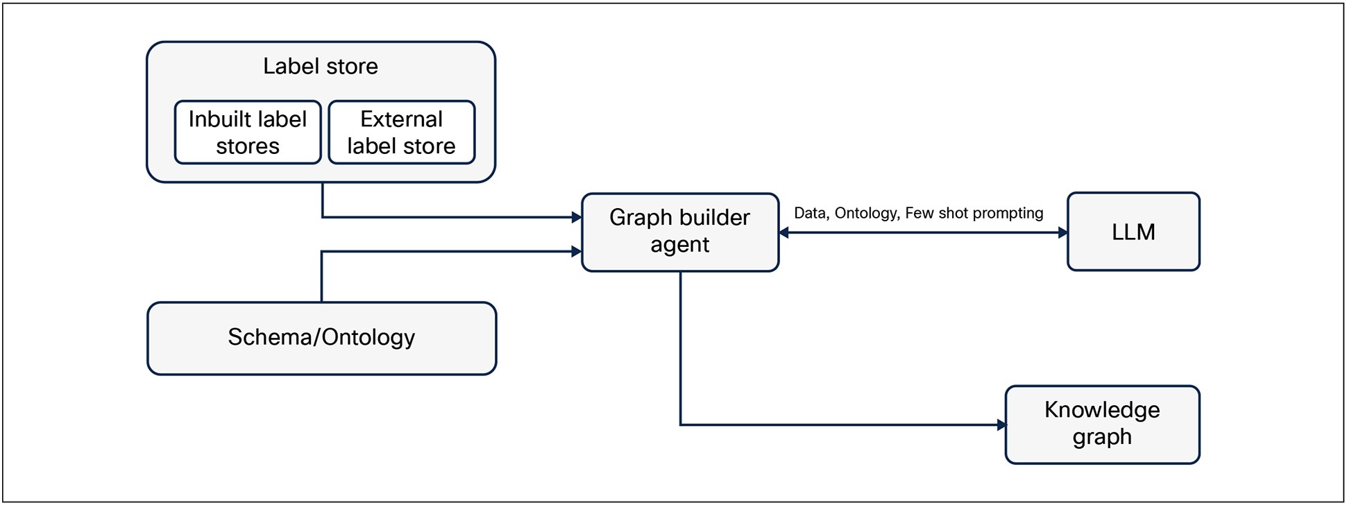
Knowledge Graph creation using Ontology, Label Store, and LLM
5.2.1 Ontology Structure
An ontology is a data model that represents knowledge by defining:
1. Entities (also called Classes or Concepts) – the “things” in your domain
2. Properties (Attributes) – the characteristics or data associated with each entity
3. Relationships (also called Object Properties or Links) – the associations between entities
A sample ontology structure is provided below to represent the idea.
5.2.1.1 Entities
● Region: Represents the geographical location of data centers
● PoP: Represents the different locations where the data centers are deployed
● ACI Pod: Represents a modular unit that includes the networking equipment necessary to host applications
● APIC Controller: Represents the SDN Controller responsible for managing a bunch of Pods in a region
● ACI EPG: Represents Endpoint Groups in ACI
● K8s Cluster: Represents that Kubernetes Cluster
● K8s Namespace: Represents Kubernetes namespaces
● K8s Pod: Represents individual pods in Kubernetes
5.2.1.2 Properties
Properties are nothing but the label metadata that has already been captured in the label stores.
5.2.1.3 Relationships
● DEPLOYED_IN
◦ POP deployed in REGION
◦ APIC Controller deployed in REGION
◦ Pod deployed in POP
◦ Kubernetes Cluster deployed in Pod
● CONTAINS
◦ Pod contains Leaf Switches, Border Leaf switches, Spines, Compute, etc.
◦ APIC contains ACI Tenants
◦ ACI Tenant contains ACI EPGs, VRF, and Bridge Domains
◦ Kubernetes cluster contains namespaces
◦ Kubernetes namespaces contain Kubernetes pods, deployments, services, etc.
● ASSOCIATED_WITH
◦ ACI Bridge domain is associated to an ACI VRF
◦ ACI EPG is associated to an ACI bridge domain
5.3 Complete RAG Framework
Additional data and information about the Telco Cloud Infrastructure such as architecture documents, design documents, as-built documentation, configuration snippets and templates, test plans, deployment best practices, security policies etc. could be vectorized and stored in a Vector Database. The Vector DB along with the Knowledge graph can work together to augment the context that is provided to the LLM. Figure 18 shows such an overall RAG Framework.
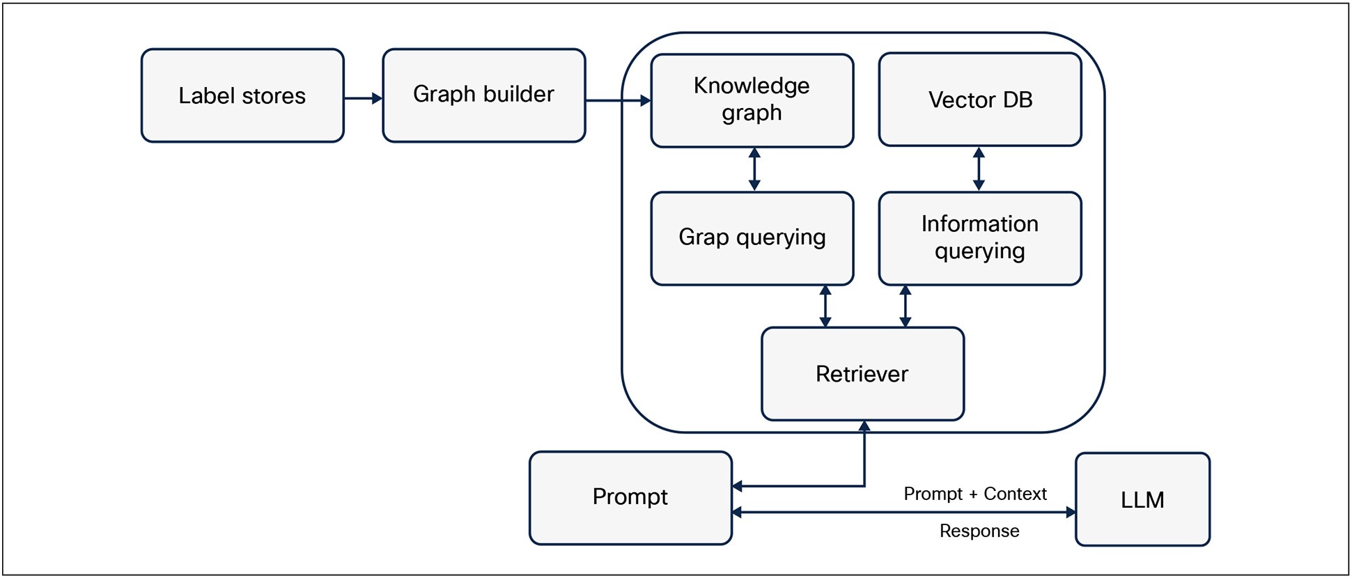
Options for integrating Label Store in RAG framework
In a Telco Cloud infrastructure, labels can act as a foundational mechanism for scalable and automated lifecycle management. They provide a flexible and powerful way to organize, classify, and automate resource management through key:value pair metadata. A well-defined labeling schema ensures operational consistency, enables automated workflows and routing decisions, enhances security and compliance, and simplifies resource discovery, lifecycle management, governance, and auditing. Extending a unified labeling schema across all domains of a public cloud infrastructure (e.g., compute, storage, networking, security, etc.) is critical for realizing the full benefits of cloud adoption.
The strategic application of labels is key for achieving scalable and automated Telco Cloud infrastructure lifecycle management. By providing a consistent and structured metadata framework, labels empower organizations to streamline operations, enhance security, and improve resource visibility across diverse infrastructure layers. The integration of external label stores along with native labelling capabilities in the Telco Cloud infrastructure domains and by the leveraging of use of network protocols to encode labels in networking updates, further extend the benefits of this approach.
As organizations look toward the future, the convergence of label-driven infrastructure management with GenAI and LLMs promises to unlock new levels of automation, intelligence, and context-aware decision-making, ultimately transforming how Telco Clouds are designed, operated, and secured. Embracing a well-defined labeling schema is a foundational requirement for realizing the full potential of Telco Cloud environments. Extending the label-based infrastructure management framework from Telco Cloud to hybrid and public clouds is both practical and strategic. By leveraging cloud-native tagging systems and ensuring consistent labels between on-premises and public cloud resources, organizations can achieve unified governance, automation, and cost management across their entire infrastructure.