Cisco Telemetry Architecture Guide
Available Languages
Bias-Free Language
The documentation set for this product strives to use bias-free language. For the purposes of this documentation set, bias-free is defined as language that does not imply discrimination based on age, disability, gender, racial identity, ethnic identity, sexual orientation, socioeconomic status, and intersectionality. Exceptions may be present in the documentation due to language that is hardcoded in the user interfaces of the product software, language used based on RFP documentation, or language that is used by a referenced third-party product. Learn more about how Cisco is using Inclusive Language.
The digitization of our businesses has produced an explosion of telemetry data that we can harness to drive better business decisions in the future. According to the IETF, network telemetry is a technology for gaining network insight and facilitating efficient and automated network management. It encompasses various techniques for remote data generation, collection, correlation, and consumption. Any information that can be extracted from networks and used to gain visibility or as a basis for actions is considered telemetry data. It includes statistics, event records and logs, snapshots of state, configuration data, etc. In addition to network-based telemetry, we can obtain telemetry from other sources such as applications. Telemetry can come in many forms such as:
● NetFlow, IPFIX, NETCONF, syslog, and SNMP data sourced from routers, switches, and firewalls
● Performance records, uptime records, and usage data from servers and applications
● Logs from public cloud providers like AWS and Azure
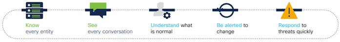
Using telemetry, we can achieve goals such as gaining visibility into network to lower troubleshooting time, tracking server utilization to plan for future growth, or understanding how customers and employees are using applications so that we can efficiently improve them with targeted upgrades. Visibility also has strong implications for network security. With this increased visibility, we can proactively find threats by understanding what is on the network, know and understand every connection to establish a baseline of normal behavior, continuously validate trust based on behavior, and do analysis during and after a security event.
Security Benefits of Visibility
As networks have scaled, it has become an increasingly difficult task to gain better visibility through monitoring and analyzing this data by ourselves. Analytical platforms are being introduced on regular basis to take advantage of this data and simplify this task, however limitations within the network infrastructure due to the lack of a sufficient telemetry architecture can cause headaches for professionals when it comes to collecting telemetry, making that data available to all telemetry destinations regardless of the product or the department it comes from, and managing it in a simple and scalable fashion.
Qualities of a Modern Telemetry Architecture
To address these shortcomings within increasingly complex networks, a better architecture is required. The core components of a modern telemetry architecture are the telemetry sources, telemetry destinations, and Telemetry Brokers. Telemetry Brokers act as mediums for telemetry data to be routed through, like how routers and switches handle IP traffic. In the enterprise network where, multiple monitored networks are common (such as a main campus, branch, and data center), brokers can be deployed for each network segment. Management and visibility into telemetry data is facilitated through a Telemetry Broker Manager. Through this architecture, several advantages are realized.
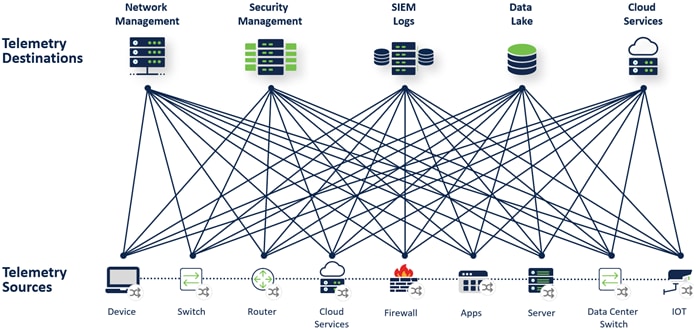
Administrators use multiple tools to get their jobs done and the need for these tools is growing. From cloud to on-prem, big vendors to homegrown, these tools compete for precious access to a limited number of telemetry data feeds. Many of these tools and devices can only send telemetry data to a single destination, effectively restricting the number of telemetry destinations that can collect and process that data.
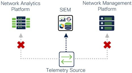
Telemetry Source Data Export Limitation
This can have multiple implications including:
● Reduced scalability and visibility due to exporting telemetry sources being unable to send telemetry data to all the telemetry destinations that need it
● Silos between departments (For example Network and Security departments) who are not easily able to share telemetry with each other
This can also lead to most, if not all telemetry data being sent to a single telemetry destination. That primary telemetry destination then holds exclusivity to the telemetry streams and the other telemetry destinations must depend on it to get telemetry data using which ever methods are supported, if telemetry sharing is a feature supported at all.
Additionally, for telemetry sources that support exporting data to multiple destinations, choosing to do so can still be a subpar decision. Replicating telemetry data at the source reduces bandwidth on all network links between the telemetry source and destination due to each telemetry stream being multiplied by the amount of telemetry destinations that traffic is routed to. Additionally, platforms may require compute resources to send multiple streams of telemetry data, reducing the performance of other tasks.
Finally, if a telemetry source only supports exporting proprietary or legacy telemetry data, it limits the number of telemetry destinations that can ingest that data.
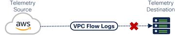
Issues consuming proprietary telemetry data
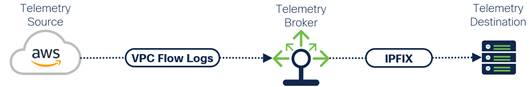
Telemetry sources such as firewalls and IoT devices can instead be configured to send telemetry traffic to a single destination – a Telemetry Broker. From there, the Telemetry Broker replicates and routes telemetry to all telemetry destinations that can use that data. Access to telemetry data is no longer limited to how many destinations the telemetry source can export to, removing limitations that would hinder scalability and visibility within a network.
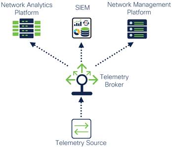
Telemetry Broker Data Replication
Because the Telemetry Broker is replicating telemetry data instead of the telemetry source or destination, there is more control over which network links will be used to forward replicated traffic. The advantage of this is being able to control where within the network telemetry data is replicated. For example, instead of exporting multiple copies of telemetry from a switch at a branch, the traffic can be replicated by a Telemetry Broker in a location closer to the telemetry sources. In addition to this, Telemetry Brokers should have the capability to discard unnecessary telemetry data, further reducing telemetry network traffic as well as reducing unnecessary processing of that data by a telemetry destination which can save licensing costs.
Finally, Telemetry Brokers should be able to transform telemetry data and protocols into formats consumable by telemetry destinations, preventing issues where a legacy or proprietary format is not able to be processed by a telemetry destination. For the most compatibility, the architecture must be extensible to support new telemetry protocols and methods of telemetry monitoring such as Model Driven Telemetry.
Transformation of proprietary telemetry data for use by an analytical platform
By transforming telemetry into formats supported by telemetry destinations, siloes between different products, technologies, or organizations can be removed, reducing gaps in visibility and taking full advantage of features offered by all telemetry destinations.
Centralized Management and Control
Management involves the upkeep of telemetry within an infrastructure. This can include maintenance, updates, adding new telemetry sources/destinations, and policy changes. Centralized management can simplify deployments and reduce the amount of time needed to make changes within the architecture, especially when those changes involve adding new destinations for telemetry data streams.
Each time a telemetry destination is added to the network or the IP or FQDN for a telemetry destination changes, without an intermediary device like a Telemetry Broker the configuration on the telemetry sources must be modified to send telemetry to that new destination. This could be a simple task with a few sources, but as the number of sources increases this task becomes ever more laborious. Current telemetry and data management options can also become expensive as more sources are added to the network, forcing teams to make tough budget choices. Even with a Telemetry Broker between the source and destination, similar issues can arise if management of multiple brokers is not centralized.
Increased Telemetry Management Complexity Due to Network Complexity
Support for a centralized Telemetry Broker Manager allows for the management of each Telemetry Broker no matter where they are, saving time and lowering costs. Furthermore, telemetry networks from new sites or acquisitions can be added without impacting existing Telemetry Broker setups.
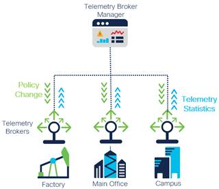
Centralized Telemetry Management
Visibility into the Telemetry Plane
Along with centralized management, there should be visibility into the devices and applications operating within the telemetry architecture. This visibility should include:
● Tracking the amount of telemetry sent from telemetry sources which can be useful for understanding how much bandwidth telemetry data is using and planning
● Tracking the telemetry protocols used within the network
● Tracking if a telemetry source is inactive or a telemetry destination goes down so you can verify reliable operation. With this visibility the appropriate parties can be notified, and the devices brought back online
Minimizing outages is important as well. Continued availability of telemetry data ensures that telemetry destinations have the information needed to provide complete event data and accurate analysis. All devices can fail, and connections can get severed for a variety of reasons. Telemetry Brokers and telemetry destinations should be set up in high availability when supported in case those devices fail for any reason.
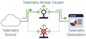
Telemetry Brokers in High Availability Cluster
Security is a concern for organizations of all sizes and the collection and transportation of telemetry data can open new attack vectors within a network. Some examples of security concerns according to the IEFT are telemetry data being manipulated to exhaust various network resources at each plane as well as the data consumer and falsified or tampered data misleading the decision-making process and paralyzing networks. Telemetry data is highly sensitive, which exposes a lot of information about the network and its configuration. Some of that information can make designing attacks against the network much easier and allows an attacker to determine whether a device may be subject to unprotected security vulnerabilities.
Often, telemetry data is sent unencrypted due to lack of support from the telemetry source. It may also be exposed on the same network as user traffic, creating the potential for traffic to be viewed by malicious entities.
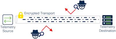
Telemetry source sending sensitive telemetry data over an encrypted transport such as TLS or IPsec
Telemetry data sent between telemetry sources, Telemetry Brokers, and telemetry destinations should be encrypted and segmented from other network traffic when possible. If the telemetry source does not support encryption, protect the data along the path using TLS, VPN, SD-WAN, or similar technologies, especially when telemetry is sent over untrusted networks such as the Internet. Firewalls can be placed within the path to ensure telemetry traffic is inspected and that unexpected traffic is blocked.
Cisco SAFE Business Flows and Capabilities
The Cisco Telemetry Architecture is defined using the Cisco SAFE methodology. For more information on SAFE please go to cisco.com/go/safe.
SAFE uses the concept of business flows to simplify the analysis and identification of threats, risks, and policy requirements for effective security. This enables the selection of very specific capabilities necessary to secure them. The following example flow is a simplified business flow highlighting the core telemetry capabilities needed to create a scalable telemetry architecture. Information on protecting telemetry business flows can be found in Appendix C.

Telemetry Business Flow
Telemetry core capabilities are considered necessary for a scalable telemetry architecture. Telemetry protection capabilities and network security capabilities can be found in Appendix C and D, respectfully.
| Capability Icon |
Capability Name |
Capability Description |
|
|
Telemetry Brokering |
Often, multiple telemetry destinations require the same telemetry data. Brokering is the replication and routing of telemetry data to multiple destinations, enabling more than one telemetry destination to obtain the same telemetry data even when the telemetry source can only send data to a single destination. |
|
|
Telemetry Filtering |
Filtering ensures telemetry destinations avoid being bogged down processing bad, duplicate, and unnecessary data. |
|
|
Telemetry Transformation |
Not all consumers of telemetry support certain telemetry data formats and some telemetry protocols are proprietary or legacy. Telemetry Protocol Transformation converts telemetry from one protocol to another for consumption by a telemetry destination. There is also Telemetry Data Transformation which reviews the telemetry data content and adds or removes fields. |
Telemetry Business Flows - Capability Mapping
Not all business flows have the same requirements. Some use cases require certain capabilities while others will not. This process allows for the application of capabilities to address administrative policy requirements.

Telemetry Business Flow with Core Capabilities
Telemetry Reference Architecture
The Cisco Telemetry Reference Architecture represented below includes the architectural components needed to deliver the core telemetry capabilities. Within this architecture, there are three separate example telemetry networks used to highlight the core telemetry capabilities and provide general recommendations for optimal Telemetry Broker placement within the network. Telemetry Broker placement could be different depending on the requirements of your network.
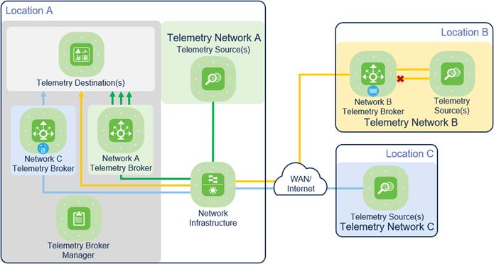
Telemetry Reference Architecture
While a single Telemetry Broker can be used to handle telemetry data, some advantages could be lost:
● Multiple Telemetry Brokers can be deployed to optimize how telemetry data is sent over the network
● Separating telemetry traffic in different locations and visibility/control for those specific locations
● Preventing a single point of failure for telemetry data
Telemetry Network A consists of telemetry sources that have telemetry data needed by multiple telemetry destinations. The Network A Telemetry Broker is set up as close as possible to the telemetry destinations. This prevents replicated telemetry data from being sent over the network infrastructure, reducing network bandwidth use between the telemetry sources and destinations.
Telemetry data from sources within the Telemetry B Network needs to be filtered before being sent to a telemetry destination. The Network B Telemetry Broker is set up as close as possible to the telemetry sources. This placement prevents unnecessary traffic from being sent over the network infrastructure and being processed by the telemetry destination.
Telemetry Network C consists of telemetry sources that use a proprietary telemetry protocol that is unsupported by the telemetry destination. In this set up, it is generally recommended for the Telemetry Broker to be placed closer to the telemetry destination. After the proprietary telemetry protocol is transformed by the Telemetry Broker, it can be consumed by the telemetry destination. If Telemetry Data Transformation (rather than Telemetry Protocol Transformation) is needed instead, it is generally recommended to place the broker closer to the sources.
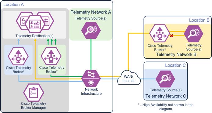
Appendix A – Telemetry Reference Architecture - Core Capabilities
Considering the design discussed in previous sections of this document, all the capabilities can be mapped to the following Cisco solution.
| Capability Icon |
Capability Name |
Cisco Security Solution |
|
|
Telemetry Brokering |
Cisco Telemetry Broker |
|
|
Telemetry Filtering |
Cisco Telemetry Broker |
|
|
Telemetry Transformation |
Cisco Telemetry Broker |
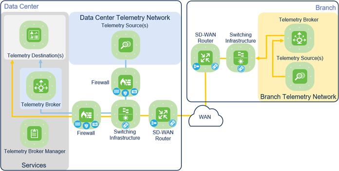
Appendix B – Telemetry Reference Design
Telemetry Reference Design
Appendix C – Securing Telemetry Business Flows
This section covers using SAFE to protect telemetry data transported through the network.
Secure Telemetry Business Flows
SAFE uses the concept of business flows to simplify the analysis and identification of threats, risks, and policy requirements for effective security. This enables the selection of very specific capabilities necessary to secure them.
Telemetry Business Flows
Threats
| Threat Icon |
Threat Name |
Threat Description |
|
|
Data Exfiltration |
Telemetry sources often send telemetry data unencrypted, creating the potential for this data to be stolen or used for reconnaissance. Telemetry data can be used to discover vulnerabilities within network devices as well as making it easier to design an attack against the network. |
|
|
Unauthorized Network Access |
Leveraging insecure telemetry sources, an attacker can use lateral movement to gain access into other parts of the network. |
|
|
Denial of Service (DoS) |
Elevated levels of telemetry data due to misconfigurations can lead to an unintentional denial of service for production traffic. Compromised telemetry sources can also be exploited to orchestrate DoS attacks against devices and services. |
Telemetry Protection Capabilities
Telemetry protection capabilities secure telemetry data as it is routed from telemetry sources to Telemetry Brokers and telemetry destinations.
| Capability Icon |
Capability Name |
Capability Description |
|
|
Macro segmentation is the process of separating a network topology into smaller sub-networks, often known as zones. A firewall is typically the enforcement point between zones in a network allowing only expected telemetry protocols |
|
|
|
Intrusion Prevention |
An intrusion prevention system (IPS) provides network visibility, security intelligence, automation, and advanced threat protection. |
|
|
Threat Intelligence |
Knowledge of emerging threats from active adversaries is shared with solutions that will utilize the information to protect the organization. |
Secure Transport
| Capability Icon |
Capability Name |
Capability Description |
|
|
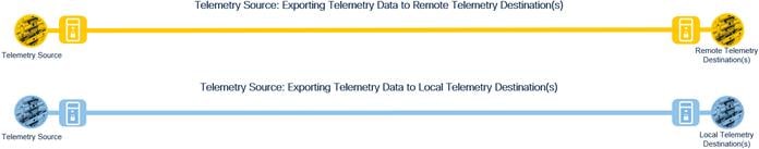
VPN |
Enables telemetry sources to securely access telemetry destinations that reside in remote locations by forming an encrypted tunnel. For remote clients, this may utilize a remote access VPN while a branch or campus might utilize a site-to-site VPN. |
|
|
Software Defined WAN |
Provides a replacement for traditional WAN routers and is agnostic to WAN transport technologies. SD-WAN provides dynamic, policy-based, application path selection across multiple WAN connections and supports service chaining for additional services such as WAN optimization and firewalls. Telemetry data sent between telemetry sources and remote telemetry destinations is securely sent. |
Tagging
| Capability Icon |
Capability Name |
Capability Description |
|
|
Tagging |
Segmentation using TrustSec Security Group Tag (SGT) or VLANs. Segmentation improves security by limiting how far an attack can spread, which is important when adding insecure telemetry sources such as IoT devices to the network. In addition to Tagging, QoS policies should be enabled to prevent telemetry data from causing a DoS attack against production traffic. |
Time Synchronization
| Capability Icon |
Capability Name |
Capability Description |
|
|
Time Synchronization |
Time synchronization within a company is a fundamental necessity for accurate log/event correlation. |
Secure Telemetry Business Flows with Mapped Capabilities
Not all business flows have the same requirements. Some use cases are subject to a smaller attack vector and therefore require less security to be applied. Some have larger and multiple vectors thus, require more. Evaluating the business flow by analyzing the attack surfaces provides the information needed to determine and apply the correct capabilities for flow specific and effective security. This process also allows for the application of capabilities to address risk and administrative policy requirements.
Secure Telemetry Business Flows with Protection Capabilities
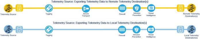
Secure Telemetry Reference Architecture
The Secure Telemetry Architecture represented below includes the architectural components needed to deliver the protection capabilities for telemetry data.
Secure Telemetry Reference Architecture
Secure Telemetry Reference Architecture - Protection Capabilities
Considering the design discussed in previous sections of this document, all the telemetry protection capabilities can be mapped to the following Cisco Solutions.
| Capability Icon |
Capability Name |
Cisco Security Solution |
|
|
Cisco Secure Firewall (ASA (Adaptive Security Appliance)) Cisco Secure Firewall (FTD (Firepower Threat Defense)) Cisco Meraki MX |
|
|
|
Intrusion Prevention |
Cisco Secure Firewall |
|
|
VPN |
Cisco Secure Client (AnyConnect) Cisco Secure Firewall (ASA (Adaptive Security Appliance)) Cisco Secure Firewall (FTD (Firepower Threat Defense)) Cisco Meraki MX Cisco Secure Connect |
|
|
SD-WAN |
Cisco Meraki Cisco Viptela |
|
|
Tagging |
Cisco Nexus/Catalyst Switch VLANs Identity Services Engine SGTs (Security Group Tags) |
|
|
Threat Intelligence |
Cisco Talos |
Secure Telemetry Reference Design
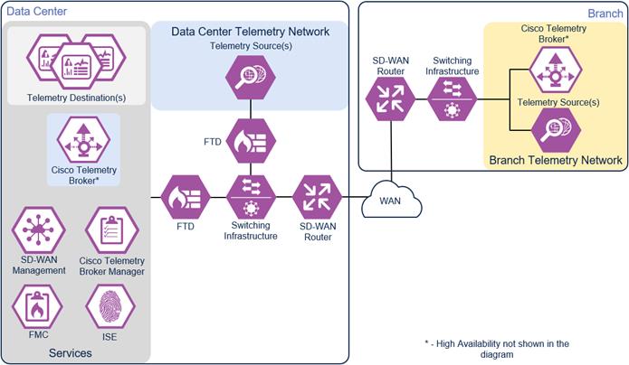
Secure Telemetry Reference Design
Network Security Capabilities
The following network security capabilities are obtained through consumption of telemetry data by various security products and analytical platforms operating as telemetry destinations. Implementation of a modern telemetry architecture ensures that these platforms get the telemetry they need to provide network security without compromise.
| Capability Icon |
Capability Name |
Capability Description |
Cisco Security Solution |
|
|
Anomaly Detection |
Anomaly detection maintains complex models of what is normal, and, in contrast, what is anomalous. Not all anomalous traffic is malicious, and therefore deviations in the network are classified into event categories to assign severity to the anomalies. |
Cisco AppDynamics Cisco Cyber Vision Cisco DNA Center Cisco Secure Cloud Analytics Cisco Secure Network Analytics Cisco Secure Workload Cisco ThousandEyes |
|
|
Flow Analytics |
Network Detection and Response (NDR) solutions leverage pre-existing infrastructure to offer enterprise-wide, contextual visibility of network traffic. Flow information can be used to conduct forensic analysis to aid in lateral threat movement investigations, ensure ongoing zero trust verification is provided, and modern tools can even detect threats in encrypted traffic. |
Cisco AppDynamics Cisco Cyber Vision Cisco Secure Cloud Analytics Cisco Secure Network Analytics Cisco Secure Workload Cisco ThousandEyes |
|
|
Logging/Reporting |
Centralized event information collection. Reviewing these events allows organizations to track historical events that can be used to baseline performance, retrieve historical information, and identify disruptions. |
Cisco Security Network Analytics Cisco Security Cloud Analytics |
|
|
Monitoring |
All telemetry starts with data collection. Monitoring allows a device or application to collect and export telemetry data for use in analytics platforms. It can include statistics, event records and logs, and much more. |
Cisco Secure Firewall Cisco Routers Cisco Secure Client (NVM) Cisco Nexus/Catalyst Switch
|
|
|
Extended detection and response (XDR) |
Extended detection and response (XDR) capabilities provide visibility and actionable insights across networks, clouds, endpoints, and applications to help Security Operation Center (SOC) teams to hunt, investigate, and remediate threats. |
Cisco SecureX |
| Acronym |
Definition |
| ASA |
Adaptive Security Appliance |
| AWS |
Amazon Web Services |
| DoS |
Denial of Service |
| Firepower Management Center |
|
| FTD |
Firepower Threat Defense |
| FQDN |
Fully Qualified Domain Name |
| IETF |
Internet Engineering Task Force |
| IoT |
Internet of Things |
| IPFIX |
IP Flow Information Export |
| IPS |
Intrusion Prevention System |
| Identity Services Engine |
|
| NDR |
Network Detection and Response |
| NETCONF |
Network Configuration Protocol |
| Network Time Protocol |
|
| NVM |
Network Visibility Module |
| SD-WAN |
Software Defined Wide Area Network |
| SGT |
Security Group Tag |
| Security Information and Event Management |
|
| SOC |
Security Operations Center |
| SNMP |
Simple Network Management Protocol |
| TLS |
Transport Layer Security |
| VLAN |
Virtual Local Area Network |
| VPN |
Virtual Private Network |
| XDR |
Extended detection and response |
If you have feedback on this design guide or any of the Cisco Security design guides, please send an email to ask-security-cvd@cisco.com.