Cisco Extends Enterprise-grade Data Center Networking to AWS Outposts
Available Languages
Bias-Free Language
The documentation set for this product strives to use bias-free language. For the purposes of this documentation set, bias-free is defined as language that does not imply discrimination based on age, disability, gender, racial identity, ethnic identity, sexual orientation, socioeconomic status, and intersectionality. Exceptions may be present in the documentation due to language that is hardcoded in the user interfaces of the product software, language used based on RFP documentation, or language that is used by a referenced third-party product. Learn more about how Cisco is using Inclusive Language.
Cisco provides scalable data center network solutions for customers today to automate their hybrid-cloud interconnects and extend multitenancy and network segmentation designs between multiple on-premises data centers and AWS regions. With the addition of AWS Outposts to the AWS product offering, Cisco customers now can use Cisco’s hybrid-cloud solution to easily connect AWS Outposts instances to their existing fabrics and leverage consistent policy-driven automation to connect workloads residing on premises and/or in the AWS cloud.
Cisco customers have deployed Cisco Nexus® 9000–based data-center fabrics widely over the last five years, taking advantage of Cisco innovations in network automation, security, and assurance. As their adoption of hybrid-cloud strategy accelerates, customers demand more flexibility to deploy application workloads on premises or in the AWS cloud while being able to access IT resources on either side. Two key requirements need to be addressed:
1. Deliver a seamless hybrid-cloud experience by extending enterprise-grade intersite network connectivity, workload segmentation, and workload mobility designs.
2. Leverage consistent policy model and governance across on-premises ACI fabrics and AWS instances in the cloud.
3. Provide cloud experience on premises through AWS Outposts for application workloads that demand low latency, storage-intensive local I/O, and data locality to meet regulatory requirements.
With the advent of AWS Outpost, customers now have the flexibility to extend Cisco data-center networking solutions to AWS Outposts in two modes:
1. Connect AWS Outposts instances to Cisco Nexus–9000 based fabrics – basic connectivity.
a. Cisco Nexus 9000–based fabric – Cisco NX-OS mode.
b. Cisco Nexus 9000–based fabric – Cisco ACI™ mode.
2. Consistent policy-based network extension and segmentation between workloads on premises and in AWS cloud – ACI mode and Cloud ACI extension to AWS.
AWS Outposts is a fully managed service that extends AWS infrastructure, AWS services, APIs, and tools to virtually any data center, colocation space, or on-premises facility for a truly consistent hybrid experience. AWS Outposts is ideal for workloads that require low-latency access to on-premises systems, local data processing, or local data storage. AWS customers can use AWS Outposts to launch Amazon Elastic Compute Cloud (EC2) instances and Amazon Elastic Block Store (EBS) volumes locally and run a range of AWS services locally on Outposts or connect to a broad range of services available in the local AWS region.
AWS Outposts will be connected to the customer’s data-center network. While Outposts itself are fully managed by AWS, easy connectivity and integration with the on-premises network is the key for successful deployment and operation of AWS Outposts. Cisco provides our customers an easy solution to connect AWS Outposts to their on-premises Cisco Nexus networks in either NX-OS or ACI mode. If ACI is the operational model of choice, our customers will also be able to extend the benefits of the Cloud ACI solution to AWS Outposts so that they can use a consistent policy model to manage the network connectivity to the AWS cloud, to AWS Outposts, and across their data centers.
Each AWS Outpost has two Top-of-Rack (ToR) switches called Outposts Network Devices (ONDs). The two Outpost Network Devices, Outpost Network Device 1 and Outpost Network Device 2, are connected to two access switches in the customer data-center network with a Link Aggregation Control Protocol (LACP) port channel of multiple member links. Layer-3 connectivity is established over VLAN SVI interfaces or Layer-3 subinterfaces with 802.01q encapsulation over the port channel. Border Gateway Protocol (BGP) routing runs over the Layer-3 links between AWS Outposts and the customers data-center network.
Each Outpost Network Device establishes two BGP sessions with the customer data-center network, one for the service link datapath and the other for the local datapath. The service link datapath is to provide the connectivity between the Outpost and its parent AWS region. Therefore, it needs to be part of the Layer-3 routing space that is eventually connected to the external routing domain to reach the AWS region. The local datapath is to provide the internal connectivity between the AWS Outpost and the customer data center. It is recommended to keep these two datapaths in two separate VRFs for better route segmentation and control between the external and internal routing spaces.
AWS Outposts in data centers with Cisco Nexus 9000 NX-OS mode
When customers choose to deploy and operate their data-center networks with Cisco Nexus 9000 Series Switches in NX-OS mode, they can build a traditional two or three-tier network using the technologies like Spanning Tree Protocol (STP) and Virtual Port Channel (vPC), but a more modern network design is to leverage BGP EVPN to build an IP-based VXLAN overlay data-center fabric. VXLAN EVPN fabrics provide enterprise grade scale, multitenancy, and workload mobility. The remainder of this section discusses the required configurations to deploy AWS Outposts to an on-premises data center in both scenarios.
A traditional three-tier data-center network consists of access, aggregation, and core tiers. The switches on the access tier normally are deployed in vPC pairs to provide redundant connectivity for endhosts and network devices that are connected to the network. The network between the access tier and the aggregation tier can be Layer 2 running STP and vPC, or Layer 3. The network between the aggregation tier and the core tier is normally Layer 3.
Figure 1 shows a three-tier network with the demarcation of Layer 2 and Layer 3 on the access tier. The switches on the access tier are in vPC pairs. It shows two typical connectivity topologies for connecting AWS Outposts to an vPC pair of access switches. In example (a), each AWS Outpost Network Device is connected to both access switches via a vPC port channel. In example (b), each AWS Outpost Network Device is connected to one access switch via a non-vPC port channel. In either example, each AWS Outpost Network Device only runs BGP routing with one access switch in a vPC pair. Although it is recommended to keep the service link datapath and the local datapath in two separate VRFs for better route segmentation and control, multi-VRF routing in a traditional two or three-tier data-center network requires a hop-by-hop VRF-lite routing configuration, which is not a common practice due to its operational complexity. Both examples have the two datapaths in the default VRF.
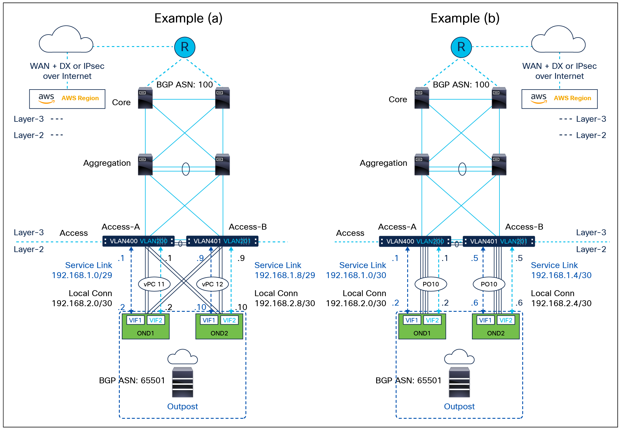
AWS Outposts on a Cisco Nexus 9000 NX-OS three-tier data-center network
In the examples shown in Figure 1, the following designs are used:
● In example (a), AWS Outpost Network Device 1 is connected to both Access-A and Access-B switches via a vPC port channel (PO11). Outpost Network Device 2 is connected to both Access-A and Access-B switches via a vPC port channel (PO12).
● In example (b), AWS Outpost Network Device 1 is connected to Access-A via a port channel (PO10 on Access-A). Outpost Network Device 2 is connected to Access-B via a port channel (PO10 on Access-B). Note: This option relies on Outposts’ internal high-availability mechanisms to deliver resilient network connectivity.
● In both examples, the on-premises network is in BGP ASN 100. The AWS Outposts is in BGP ASN 65501.
● In both examples, AWS Outpost Network Device 1 has two BGP peerings with Access-A, one in VLAN 400 for service-link connectivity and the other in VLAN 200 for local connectivity. AWS Outpost Network Device 2 has two BGP peerings with Access-B, one in VLAN 401 for service link connectivity and the other in VLAN 201 for local connectivity.
Tables 1 and 2, below, show the relevant configurations for the AWS Outposts deployment on both Access-A and Access-B in example (a) and (b), respectively. It assumes that the vPC configuration between the two switches has been implemented. For a reference on basic vPC configuration, use the following configuration guide: https://www.cisco.com/c/en/us/td/docs/switches/datacenter/nexus9000/sw/6-x/interfaces/configuration/guide/b_Cisco_Nexus_9000_Series_NX-OS_Interfaces_Configuration_Guide/configuring_vpcs.pdf.
Table 1. Required access-switch configurations in example (a) for AWS Outposts deployment
| Access-A |
Access-B |
| interface port-channel11 switchport switchport mode trunk switchport trunk allowed vlan 200,400 vpc 11
interface port-channel12 switchport switchport mode trunk switchport trunk allowed vlan 201,401 vpc 12
interface Ethernet1/1-2 switchport switchport mode trunk switchport trunk allowed vlan 200,400 channel-group 11 no shutdown
interface Ethernet1/3-4 switchport switchport mode trunk switchport trunk allowed vlan 201,401 channel-group 12 no shutdown
interface Vlan200 no shutdown ip address 192.168.2.1/29
interface Vlan201 no shutdown ip address 192.168.2.11/29
interface Vlan400 no shutdown ip address 192.168.1.1/29
interface Vlan401 no shutdown ip address 192.168.1.11/29
router bgp 100 router-id 1.1.1.1 neighbor 192.168.1.2 ßAWS Outpost Network Device 1 service link datapath remote-as 65501 address-family ipv4 unicast neighbor 192.168.2.2 ß AWS Outpost Network Device 1 local datapath remote-as 65501 address-family ipv4 unicast |
interface port-channel11 switchport switchport mode trunk switchport trunk allowed vlan 200,400 vpc 11
interface port-channel12 switchport switchport mode trunk switchport trunk allowed vlan 201,401 vpc 12
interface Ethernet1/1-2 switchport switchport mode trunk switchport trunk allowed vlan 200,400 channel-group 11 no shutdown
interface Ethernet1/3-4 switchport switchport mode trunk switchport trunk allowed vlan 201,401 channel-group 12 no shutdown
interface Vlan200 no shutdown ip address 192.168.2.3/29
interface Vlan201 no shutdown ip address 192.168.2.9/29
interface Vlan400 no shutdown ip address 192.168.1.3/29
interface Vlan401 no shutdown ip address 192.168.1.9/29
router bgp 100 router-id 2.2.2.2 neighbor 192.168.1.10 ßAWS Outpost Network Device 2 service link datapath remote-as 65501 address-family ipv4 unicast neighbor 192.168.2.10 ßAWS Outpost Network Device 2 service local datapath remote-as 65501 address-family ipv4 unicast |
Table 2. Required access-switch configurations in example (b) for AWS Outposts deployment
| Access-A |
Access-B |
| interface port-channel10 switchport switchport mode trunk switchport trunk allowed vlan 200,400
interface Ethernet1/1-4 switchport switchport mode trunk switchport trunk allowed vlan 200,400 channel-group 10 no shutdown
interface Vlan200 no shutdown ip address 192.168.2.1/30
interface Vlan400 no shutdown ip address 192.168.1.1/30
router bgp 100 router-id 1.1.1.1 neighbor 192.168.1.2 ßAWS Outpost Network Device 1 service link datapath remote-as 65501 address-family ipv4 unicast neighbor 192.168.2.2 ß AWS Outpost Network Device 1 local datapath remote-as 65501 address-family ipv4 unicast |
interface port-channel10 switchport switchport mode trunk switchport trunk allowed vlan 201,401
interface Ethernet1/1-4 switchport switchport mode trunk switchport trunk allowed vlan 201,401 channel-group 10 no shutdown
interface Vlan201 no shutdown ip address 192.168.2.5/30
interface Vlan401 no shutdown ip address 192.168.1.5/30
router bgp 100 router-id 2.2.2.2 neighbor 192.168.1.6 ßAWS Outpost Network Device 2 service link datapath remote-as 65501 address-family ipv4 unicast neighbor 192.168.2.6 ßAWS Outpost Network Device 2 service local datapath remote-as 65501 address-family ipv4 unicast |
| Note: In this example, PO10 on both access switches are not vPC port-channel; they are local to Access-A or Access-B. VLAN 200, 201, 400, and 401 are non-vPC VLANs. VLAN 200 and 400 are only on Access-A while VLAN 201 and 401 are only on Access-B. They must be removed from the allowed VLAN list of the vPC peer link. |
|
Figure 2 illustrates a typical topology and design to connect AWS Outposts to an NX-OS VXLAN fabric. The two Outpost Network Devices of an AWS Outpost are connected to two different leaf switches of the on-premises data-center network via LACP port channels. Two Layer-3 subinterfaces are configured, one for the internal local datapath and the other for the service link datapath to the AWS region. They are in two different VRFs. BGP peer is established between each of the subinterfaces and AWS Outposts. The service link connectivity to the AWS region goes through the existing border-leaf switch that runs dynamic routing with the customer organization network outside of the data-center network to provide external connectivity to WAN or the Internet.
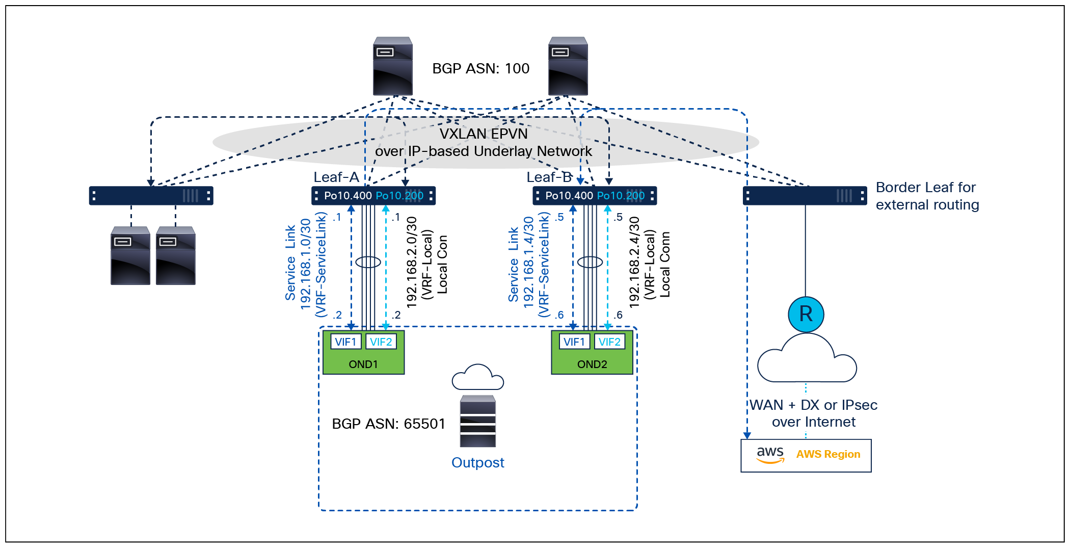
AWS Outposts on Cisco Nexus 9000 NX-OS VXLAN fabric
In the example shown in Figure 2, the following design is used:
● Two VRFs, vrf-local and vrf-servicelink, are created for the local routing and for Outpost service link connectivity to the AWS region, respectively.
● The port channel 10 is configured on each leaf switch.
● Subinterface Po10.400 is configured for Layer-3 connectivity with AWS Outpost Network Device VIF1 (IP addresses are indicated in Figure 1) for the service link. It is in vrf-servicelink.
● Subinterface Po10.200 is configured for Layer-3 connectivity with AWS Outpost Network Device VIF2 (IP addresses are indicated in Figure 2) for local connectivity. It is in vrf-local.
● The on-premises network is in BGP ASN 100.
● The AWS Outpost is in BGP ASN 65501.
● The leaf switches are running BGP EVPN as a control protocol.
● BGP routing between the leaf switches and the AWS Outpost Network Devices runs in the IPv4 unicast address-family in vrf-servicelink and vrf-local, respectively. The BGP-learned VRF routes are advertised into the L2VPN EVN address-family for further propagation to the rest of the network in the corresponding VRF.
The table below shows the required Cisco Nexus 9000 leaf switch configuration for the above design, including the two VRFs, port-channel interface and subinterfaces, and BGP routing with the AWS Outpost Network Devices.
Note: A detailed explanation of the switch configuration is not in the scope of this document. Refer to the following configuration guide for Cisco Nexus 9000 Series Switch BGP EVPN configuration: https://www.cisco.com/c/en/us/td/docs/switches/datacenter/nexus9000/sw/93x/vxlan/configuration/guide/b-cisco-nexus-9000-series-nx-os-vxlan-configuration-guide-93x.html.
Table 3. Required leaf-switch configuration for AWS Outposts deployment in Cisco Nexus 9000 VXLAN EVPN fabric
| Configuration on Leaf-A |
Configuration on Leaf-B |
| vrf context vrf-local <- VRF for AWS Outposts local datapath vni 60200 rd auto address-family ipv4 unicast route-target import 100:60200 route-target export 100:60200 route-target both auto evpn vrf context vrf-servicelink <- VRF for AWS Outposts service link datapath vni 60400 rd auto address-family ipv4 unicast route-target import 100:60400 route-target export 100:60400 route-target both auto evpn
interface Ethernet1/1-4 channel-group 10 no shutdown
interface port-channel10
interface port-channel10.200 description outpost local connectivity encapsulation dot1q 200 vrf member vrf-local ip address 192.168.2.1/30 no shutdown
interface port-channel10.400 description outpost service-link encapsulation dot1q 400 vrf member vrf-servicelink ip address 192.168.1.1/30 no shutdown
router bgp 100 log-neighbor-changes address-family ipv4 unicast address-family l2vpn evpn vrf vrf-servicelink address-family ipv4 unicast advertise l2vpn evpn neighbor 192.168.1.2 <- Outpost Network Device 1 VIF1 remote-as 65501 address-family ipv4 unicast default-originate <-Optional vrf vrf-local address-family ipv4 unicast advertise l2vpn evpn neighbor 192.168.2.2 <- Outpost Network Device 1 VIF2 remote-as 65501 address-family ipv4 unicast |
vrf context vrf-local <- VRF for AWS Outposts local datapath vni 60200 rd auto address-family ipv4 unicast route-target import 100:60200 route-target export 100:60200 route-target both auto evpn vrf context vrf-servicelink <- VRF for AWS Outposts service link datapath vni 60400 rd auto address-family ipv4 unicast route-target import 100:60400 route-target export 100:60400 route-target both auto evpn
interface Ethernet1/1-4 channel-group 10 no shutdown
interface port-channel10
interface port-channel10.200 description outpost local connectivity encapsulation dot1q 200 vrf member vrf-local ip address 192.168.2.5/30 no shutdown
interface port-channel10.400 description outpost service-link encapsulation dot1q 400 vrf member vrf-servicelink ip address 192.168.1.5/30 no shutdown
router bgp 100 log-neighbor-changes address-family ipv4 unicast address-family l2vpn evpn vrf vrf-servicelink address-family ipv4 unicast advertise l2vpn evpn neighbor 192.168.1.2 <- Outpost Network Device 2 VIF1 remote-as 65501 address-family ipv4 unicast default-originate <- Optional vrf vrf-local address-family ipv4 unicast advertise l2vpn evpn neighbor 192.168.2.6 <- Outpost Network Device 2 VIF2 remote-as 65501 address-family ipv4 unicast |
AWS Outposts in data centers with Cisco Nexus 9000 ACI mode
With Cisco ACI, customers can enable workload mobility, automate service chaining functions, and enforce their security posture in a consistent manner across on-premises ACI fabrics.
Figure 3 shows the typical topology and design for connecting AWS Outposts to a Cisco ACI fabric network. The physical topology is similar to that of NX-OS VXLAN EVPN fabric, but the Layer-3 subinterfaces and BGP routing are provisioned as part of an L3Out on the ACI fabric.
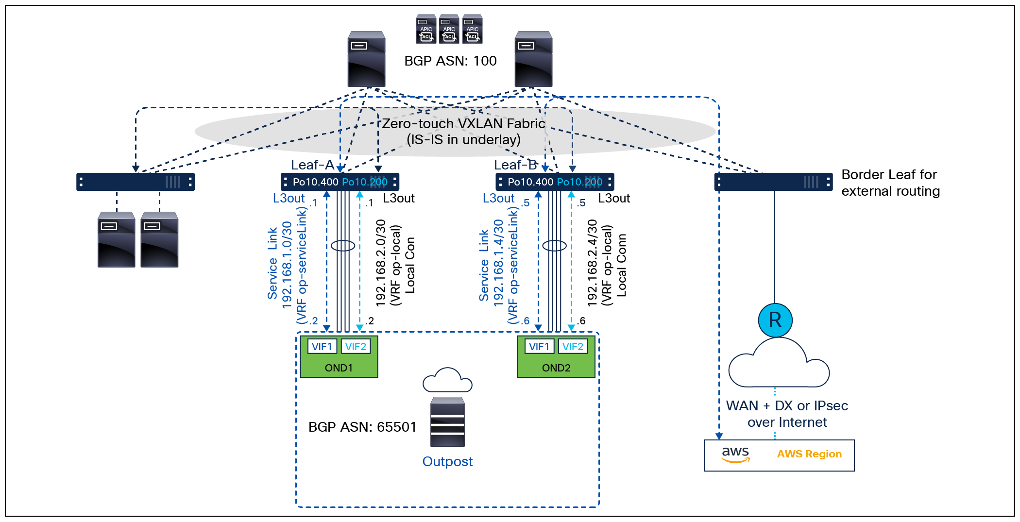
AWS Outposts on Cisco ACI fabric network
In the example shown in Figure 3, the following two L3Out objects are defined, one for the AWS Outposts local datapath, and the other for the AWS Outposts service link datapath. They are in VRF op-local and VRF op-servicelink, respectively. The configuration is centrally defined on the Application Policy Infrastructure Controller (APIC).
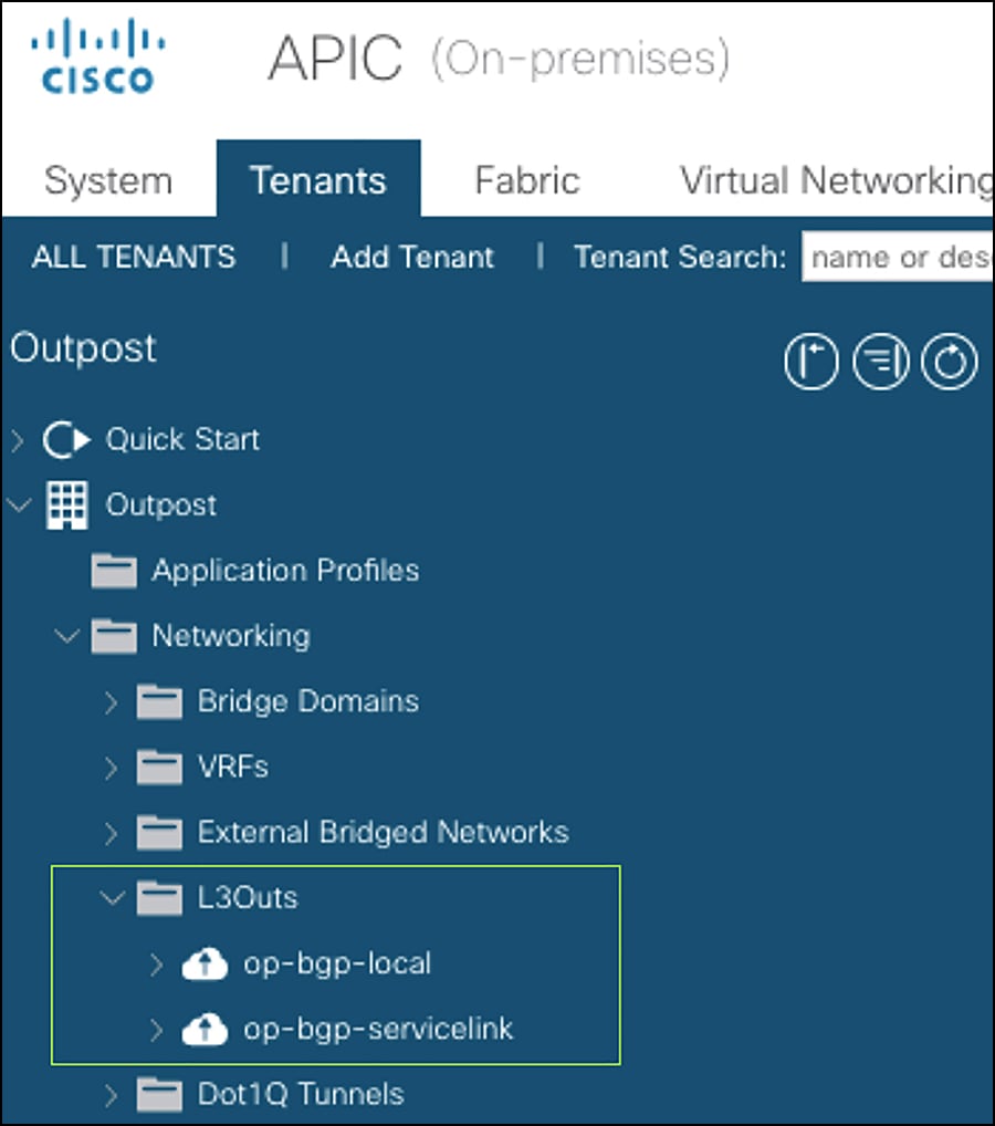
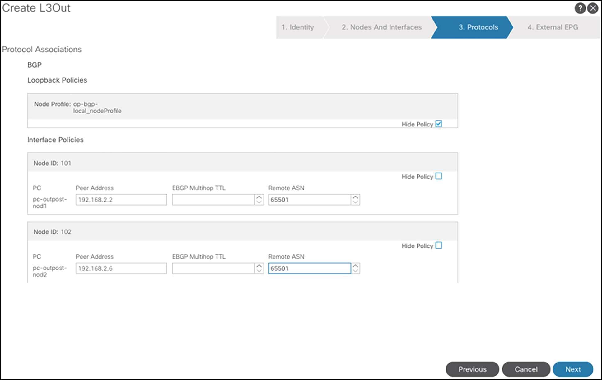
Figure 4 shows the steps to configure the L3Out op-bgp-servicelink on APIC GUI.
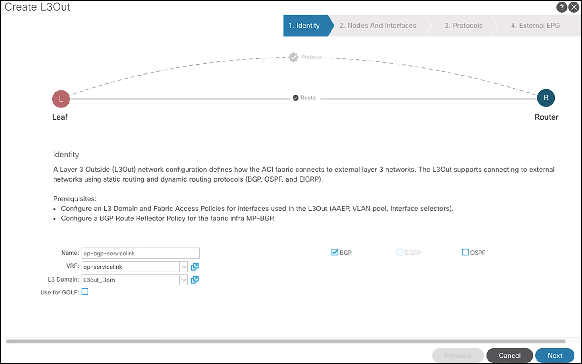
Configuring the L3Out op-bgp-servicelink
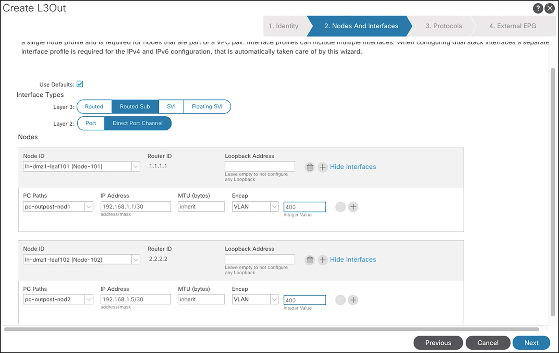
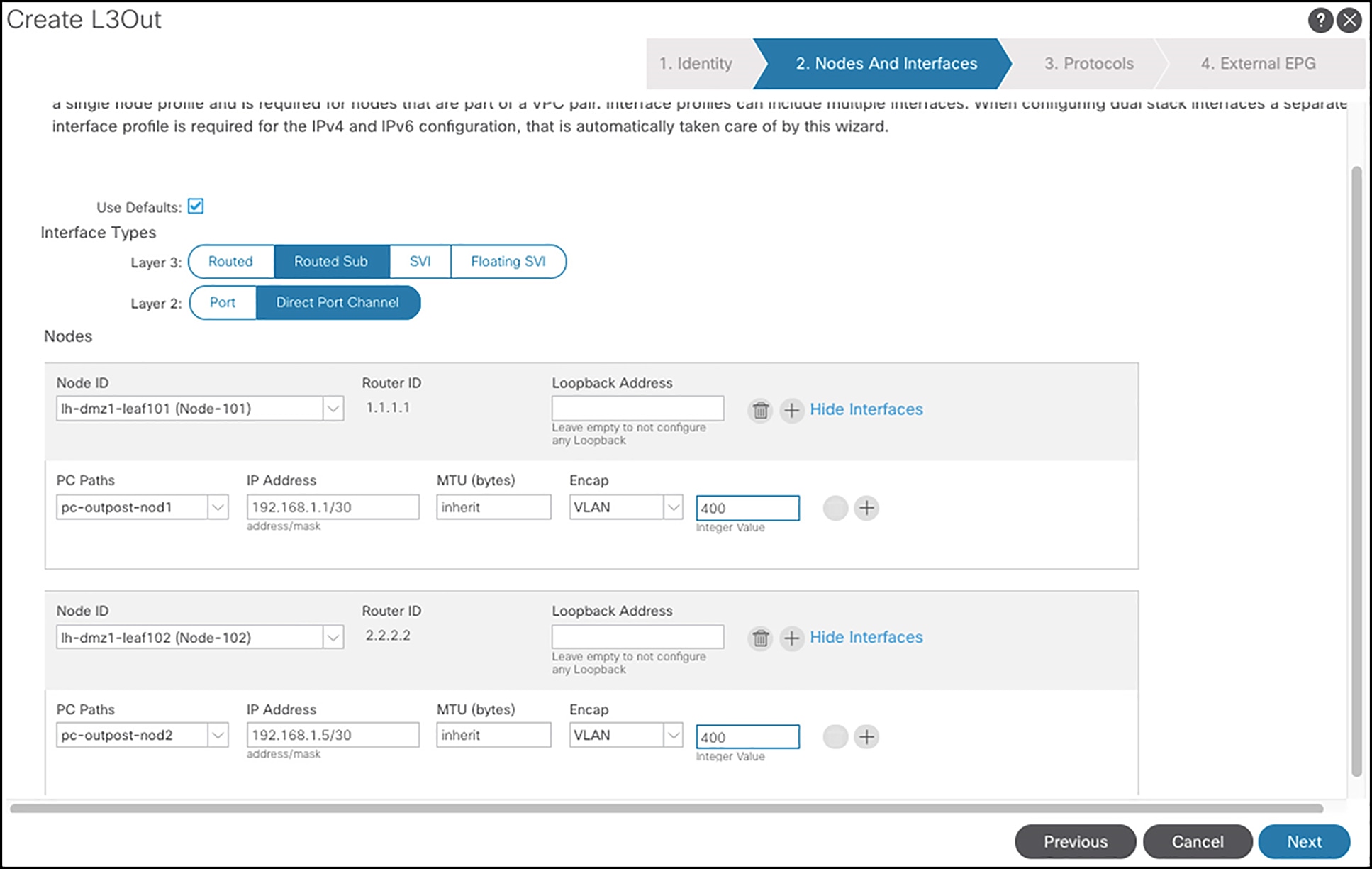
Figure 5 shows the steps to configure the L3Out op-bgp-local on APIC GUI.

Configuring L3out op-bgp-local

Note: The above shows the configuration using the APIC GUI interface. Customers can also use the APIC API to program the fabric.