Understand and Manage ECMP Scale in Cisco ACI White Paper
Available Languages
Bias-Free Language
The documentation set for this product strives to use bias-free language. For the purposes of this documentation set, bias-free is defined as language that does not imply discrimination based on age, disability, gender, racial identity, ethnic identity, sexual orientation, socioeconomic status, and intersectionality. Exceptions may be present in the documentation due to language that is hardcoded in the user interfaces of the product software, language used based on RFP documentation, or language that is used by a referenced third-party product. Learn more about how Cisco is using Inclusive Language.
In a data center network, a single service can be provided through multiple virtual or container network functions. Services might be reachable through a single loopback IP or through several network functions each of which has an individual IP address. This kind of scenario requires a very high ECMP scale on data-center leaf and spine switches. Cisco provides a highly redundant solution through a Cisco ACI® fabric. Hence, it is important to understand how ECMP scale is managed within such a fabric and what major events affect it. This white paper provides an insight into ECMP scale management in a Cisco ACI fabric.
What ECMP is and how it works in Cisco ACI
ECMP (equal cost multipath) is a method to utilize multiple same-cost paths to route a packet to a destination. With ECMP you can have more than one IP route installed in a routing table and have the capability to hash or load balance traffic flows through these routes. The major benefit of using ECMP is to be able to utilize all available paths across the network and hence improve resource utilization across the network. Without ECMP there will be only one preferred path available in the routing table, and other routes or paths will act as backup. The figure below compares the network with and without ECMP. Here, even though there are two equal cost paths available between the network - 192.168.10.0/24 and 192.168.20.0/24 – there will be only one path installed in the routing table for the non-ECMP network; the other path will remain unutilized until the primary path fails. On the other hand, with ECMP enabled in the network, both equal-cost paths can be used at the same time by load sharing over each of them.
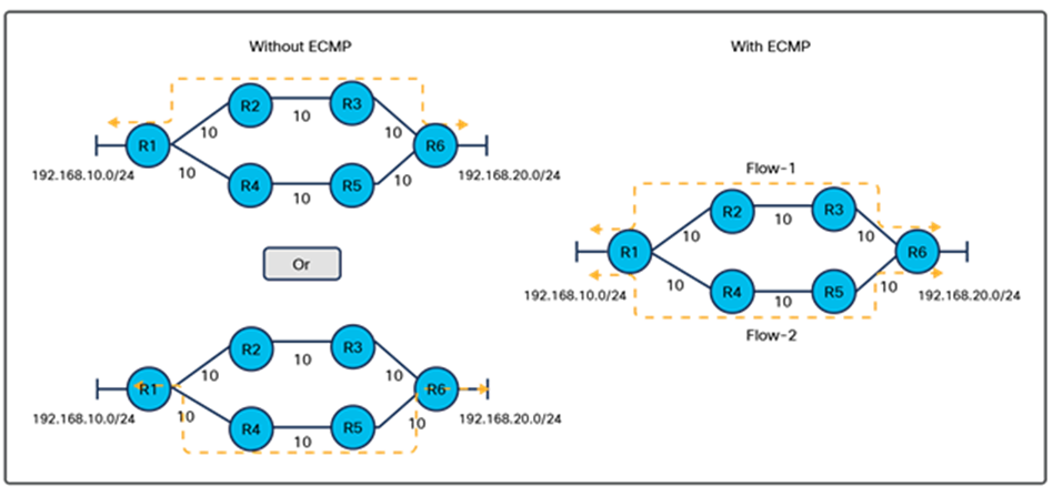
Routing paths in ECMP and in non-ECMP networks
In Cisco APIC 6.0(1) and older releases, we support 64-way ECMP in an ACI fabric, which means that we can have 64 equal-cost paths available for a particular network prefix. Packets will be distributed over the available paths based on the 5-tuple hashing algorithm, which considers source IP, destination IP, source port, destination port, and protocol type as parameters.
In this part of the document, we will try to understand how ECMP records are created on the switch platform. To record an ECMP entry in the hardware, the switch creates three kinds of objects: ECMP groups, members, and next-hop IP. To forward the packet out of the switch the switch needs to know the layer 2 rewrite information. The Layer-2 rewrite information chain is different for normal routes and ECMP routes. For ECMP routes we create additional records (such as groups, members, etc.) that will eventually point to the Layer-2 rewrite information, as shown in the figures below.
In Figure 2, we see an example of a non-ECMP route, where we have only one next-hop IP. In this case the platform stores the route as a chain-of-destination prefix; that points to next-hop IPs, which eventually point to Layer-2 rewrite information.
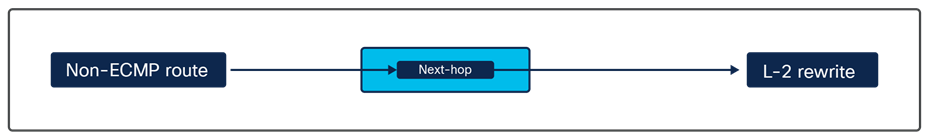
How Layer-2 rewrite information is derived for a non-ECMP route
In Figure 3 we see an ECMP route. The switch platform stores the route information as a forwarding chain where the ECMP route points to a Group-ID that consists of group members pointing to the next-hop IPs. Every next-hop IP will eventually point to the corresponding Layer-2 rewrite information to complete the forwarding chain.
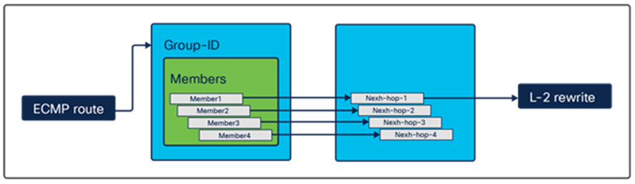
How Layer-2 rewrite information is derived for an ECMP route
Now let’s try to define groups and other objects in more detail.
Group: A group can be defined as a set of next-hop IPs pointing to a prefix destination. For example, in the figure below we have IP destination network 10.1.1.0/24 pointing to four IP addresses (next-hop IPs). Here one group is created to record the set of next-hops pointing to a destination, the group ID is a unique ID (ABC123 in this case) assigned to the group that will be referred by the destination prefix to derive the forwarding chain.
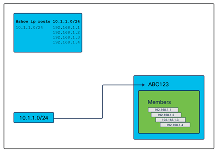
Group-ID in an ECMP record
Members: Members are group elements where we store the next-hop information. Next-hop IP addresses inside a group can be called as group members. For example, we have four members in the group in the figure below.
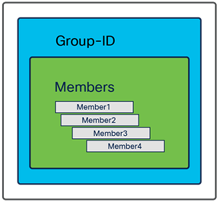
Members in an ECMP record
Next-hop: “Next-hop” is a traditional next-hop in an IP routing table where the packet destined for a particular destination is sent for routing. The essential difference between member and next-hop IPs lies in the method we use to store their information. Members are the data structure elements in the group; the next-hop is a global table in a switch – hence we can avoid the duplication of entries in the next-hop table. On the other hand, two different groups may have a similar list of members. We will explain this by using examples in the next section.
ECMP scale and how it is consumed on a platform
The table below shows the scale numbers that are common on all Cisco ACI leaf switches. The ECMP scales shown below do not change with the routed protocols, which means that a given scale remains the same for IPv4 and IPv6. Also, the scale is consistent for all forwarding profiles on a switch.
Table 1. Cisco ACI leaf switches scales.
| Value |
Scale |
| Group |
4096 |
| Member |
32,768 |
| Next-Hop |
8192 |
Note: The scales listed above are global scales on a switch. A leaf switch doesn’t provide per-VRF (virtual route forwarding) scales for ECMP. If an ECMP prefix learned from a border leaf is imported into all the VRFs in a non-border leaf, then the overall ECMP record utilization on the non-border leaf will be the collective utilization of ECMP records on every VRF for that prefix.
Now let’s see how scales are managed in Cisco ACI. We will try to understand this with the help of few examples.
1. In our first example, let’s see how the ECMP records are consumed when there are two different ECMP destination prefixes in the routing table and some of the next-hop IPs between the groups are similar. In this case we have 192.168.1.1 and 192.168.1.2 common to both destination prefixes – that is, 10.1.1.0/24 and 10.1.2.0/24. In the table below, we see that for each destination prefix we have a group, Group-1 for 10.1.1.0/24 and Group-2 for 10.1.2.0/24. Each group has three members, which translate to three next-hop IPs. As a result of these records, the platform will have a total of two groups, six members, and four next-hops consumed from the total scale available, described in the table above. The platform does not need to store duplicate next-hop values; hence, we have four next-hop IPs instead of six.
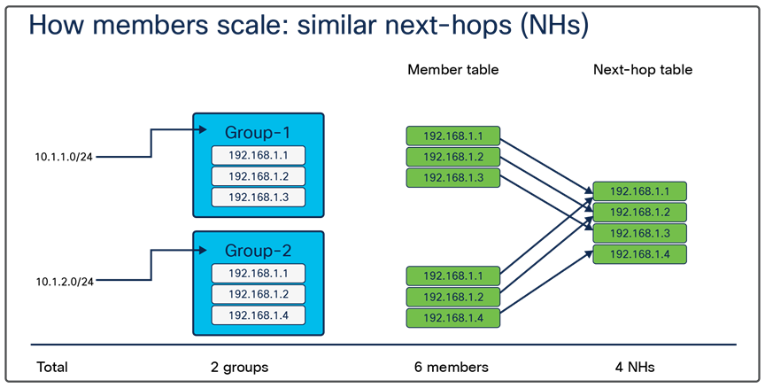
ECMP usage in similar next-hops
2. Unlike the example given above, now we have non-overlapping next-hop IPs as our destination prefixes. The prefix 10.1.1.0/24 is learned from three next-hop IPs 192.168.1.1, 192.168.1.2, and 192.168.1.3. Similarly, the destination prefix 10.1.2.0/24 is learned from 192.168.1.4, 192.168.1.5, and 192.168.1.6. Now let’s check how the ECMP records are consumed in this case. Here, we create one group for each destination prefix, and three members and three next-hop IPs for each group; hence, a total of two groups, six members, and six next-hops. It is important to note that we have six next-hops in this case, because the next-hops are not duplicates, which they were in the example above.
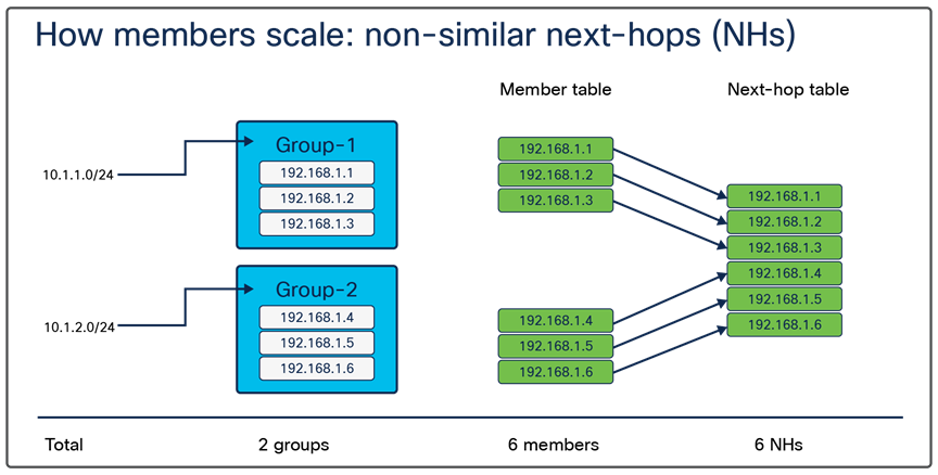
ECMP usage in the case of non-similar next-hops
How ECMP records are updated when there are changes in the network
We have seen the ECMP scale and how is it consumed on the platform. It is also important to understand how a network change affects the ECMP scale in a situation where a next-hop IP disappears or a new next-hop IP appears for a destination prefix. Let’s try to understand how the platform responds to these changes and updates the ECMP record.
In both scenarios the switch platform updates the record in the three steps given below:
1. Create a new group record with the updated members and next-hops.
2. Update the pointers for the destination prefix to the new group.
3. Delete the old group record.
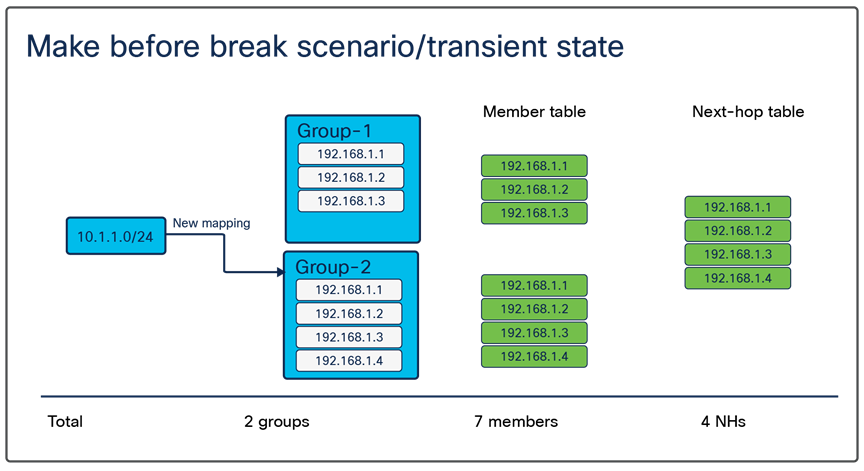
Example use case 1: We will try to understand this with the help of an example. Consider a network prefix 10.1.1.0/24 for which a new next-hop 192.168.1.4 needs to be added in the ECMP. The figure below represents a transient state the system goes through while updating this record. At this state, the switch creates a new group (Group-2) with four members including new member (192.168.1.4). Once this state is achieved, we update the pointers for the prefix 10.1.1.0/24 to the new group (Group-2) and delete the old ECMP record (Group-1). We will name this method of updating the ECMP record make-before-break, because the name suggests we are creating the new record before deleting the old one.
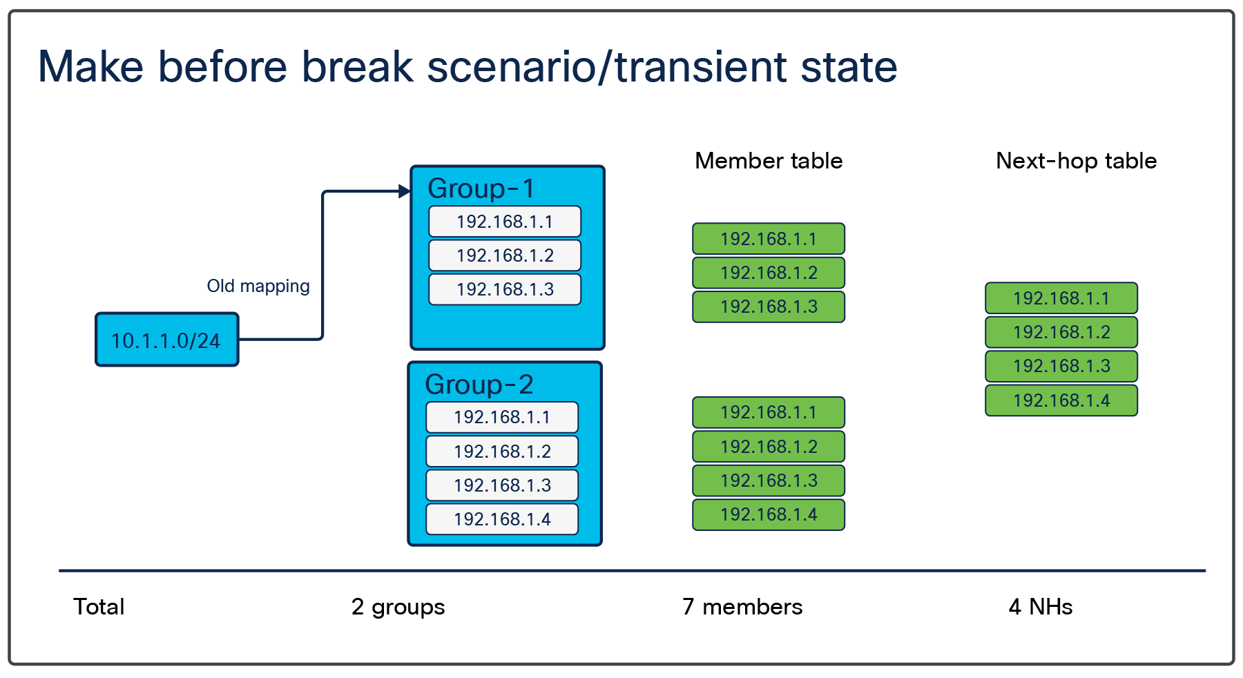
Creating a new group: transient state
New mapping updated
Now let’s see how the ECMP resources look after we update all of the new records and delete the old ones with the help of Example use case 1. In a steady state, the platform looks like the figure below. Here we have deleted the old record; now there is just one group with four members and next-hops are available. Note that, in the transient state, a higher number of ECMP records is used on the switch. A steady state normalizes record utilization.
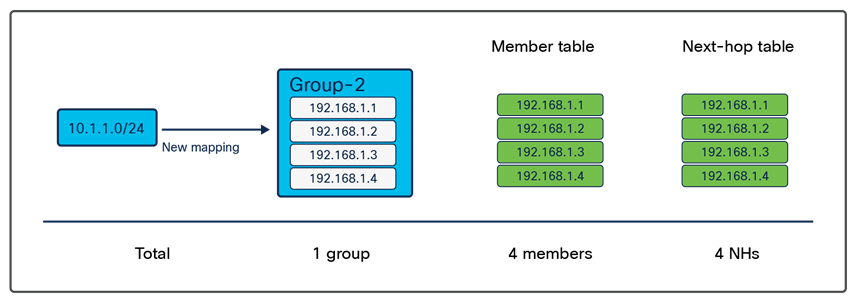
Steady state, old groups deleted
Example use case 2: We will take another example to enhance our understanding of ECMP scale implications and its handling by the switch.
From Cisco® APIC Release 5.2, Cisco ACI allows you to have a recursive next-hop for the externally learned routes. For example, in some specific cases, such as a floating L3Out scenario, we can have a route for which the next-hop is recursively reachable by an ECMP route. In the routing table below, the next-hop for 10.10.0.0/16, 192.168.1.1 has another set of ECMP routes, 172.16.1.1 and 172.16.2.1, available in the routing table.
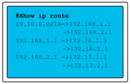
Routing table with recursive next-hops
Here, adding a new next-hop for 192.168.1.1 will make the routing table look like the figure below. In this case, we are not updating next-hops for the route prefix 10.10.0.0/16; instead, the change is for the prefix 192.168.1.1. This change will affect the 10.10.0.0/16 route as well. In Cisco ACI, this kind of route update is called an ECMP update.
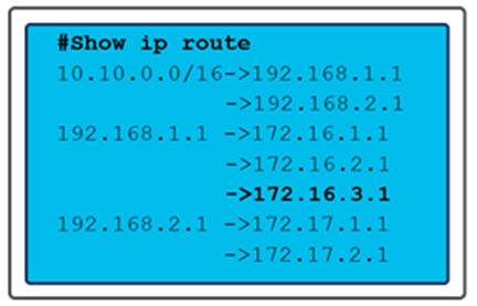
Routing table with recursive next-hops, with a new next-hop entry
To update all the dependencies in this use case, we follow the approach illustrated in the figure below. We first update the ECMP record for a Recursive Next-Hop (RNH) route (in this case, 192.168.1.1) by creating a new ECMP group with the new entry (172.16.3.1); as illustrated in figures 8, 9, and 10. Then we update all the dependent routes, such as 10.10.0.0/16, to the new ECMP Group-ID and then delete the old ECMP group.
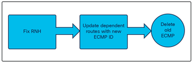
ECMP record update flow
Here note that, as discussed in the previous section on the transient state, we will have old and new ECMP records available on the switch platform at the same time. Keeping these duplicate entries increases ECMP scale utilization.
Example use case 3: Another important use case is encountered when border leaf switches are added to a Cisco ACI fabric. Let’s consider that we have one Non-Border Leaf (NBL) and three Border Leaf (BL) switches. All BLs learn and propagate the same set of routes to the NBL. However, it is not necessary that all three BLs learn and propagate the routes at the same time. This behavior will create a transient state on the NBL resulting in higher utilization of ECMP groups and members. The two figures below illustrate the difference between the ECMP scale in transient and stable states in this use case. Here, we have three BLs – BL1, BL2, and BL3 – learning external prefixes 10.1.1.0/24, 10.1.2.0/24, 10.1.3.0/24, and 10.1.4.0/24. Considering all of the BLs are powering up, each BL will take a different amount of time to learn the four prefixes. At a given time it is possible, for example, that BL1 has learned only two prefixes while BL2 has learned three. Also, the BLs will not wait to learn all four prefixes to send route updates to the NBL, hence creating a transient state on the NBL, with a higher number of groups and members being utilized on the NBL. The maximum utilization of all ECMP resources on an NBL can be calculated with the two formulas below. Here “n” is the number of BLs in the fabric.
ECMP group: 2 ^ n - n - 1
ECMP members: (n* (2 ^ (n-1) )) – n
In the figure below, we see that, although all of the BLs should learn all four prefixes, at present the BLs have learned only three different combinations of prefixes. These prefixes are sent to the NBL where the ECMP scale is being affected due to the transient state of the network.
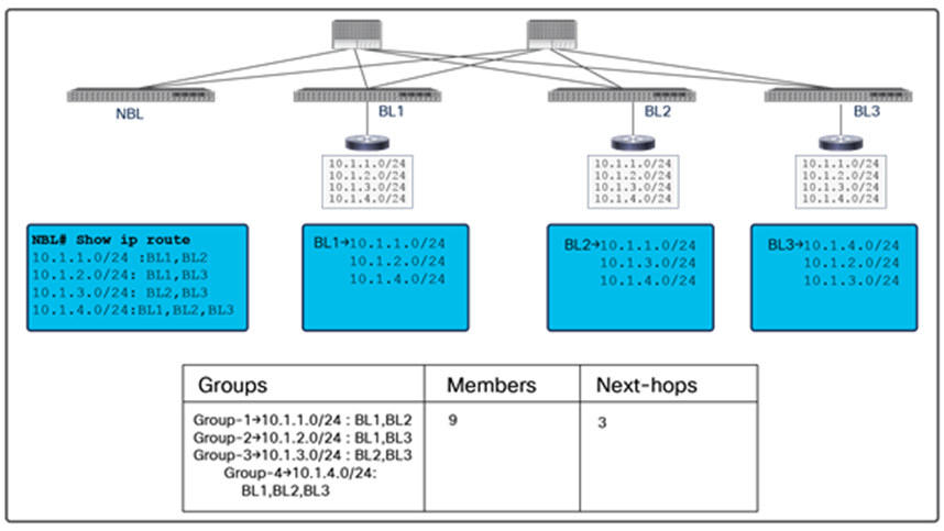
Groups and members in a transient state
In the figure below, we see that eventually the network has fully converged, and all of the BLs have learned the four available prefixes. This stabilizes the ECMP scale situation on the NBL as well, and we see a drop on the member scale to 3.
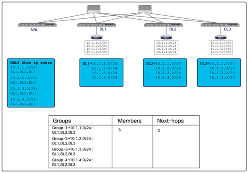
Groups and members in a stable state
It is exceedingly rare to see this use case but important to understand the implications of border leaf bring-up on ECMP scale.
“With the three use cases described above, we understand that in each case the switch must go through a transient state of keeping duplicate entries of ECMP records, and that during this state the utilization of ECMP records increases.”
In scenarios where we have a high number of ECMP records, this can cause scale issues on the switch. Hence it is especially important that we understand the ECMP scale and the factors that can affect it. Now, as we understand the factors that can affect the scale, let’s see how we can avoid scale issues on the switch.
1. Track the scale: We recommend keeping track of the ECMP scale of the switch while making a change that can affect the routing tables in an ACI fabric. It is always a better idea to have an incremental upgrade plan; for example, if we need to add two links to the ACI fabric that can increase the ECMP next-hops for external route prefixes, we should add one link and monitor the ECMP scale on the leaf switches and then add the second link. Similarly, if we need to add two border leafs to the fabric, add them one by one. The idea behind the incremental upgrade is to give time to the leaf switches to achieve a steady state, as discussed in the previous section. Below is a CLI we can run on a leaf switch (generation 2 or later) to see the current ECMP member scale.
Leaf-101#vsh_lc -c 'show plat int hal health-stats' | grep ecmp
max_uc_ecmp_entries : 32768
uc_ecmp_entries : 2
uc_ecmp_entries_norm : 0
2. There can be many unplanned events, such as link or node failures, that can cause route churn in an ACI fabric. It is difficult to plan for such events but good to know the right impact, the idea is to understand how much we can stress the ECMP scale on the switch so that in case of any route churn there is still some space available to accommodate make-before-break scenario.
The goal of this paper is to educate the reader about ECMP and provide an overview of ECMP scale calculations in different scenarios on Cisco ACI fabrics. It is important for network administrators to understand a platform’s ECMP scale, monitor it, and design the network accordingly. It is not always possible to have calculated scale numbers before a network change, but it is important to be aware of relevant parameters and their limits and perform a better-informed activity and that is where this document should help.