Randomized and Changing MAC Deployment Guide
Available Languages
Bias-Free Language
The documentation set for this product strives to use bias-free language. For the purposes of this documentation set, bias-free is defined as language that does not imply discrimination based on age, disability, gender, racial identity, ethnic identity, sexual orientation, socioeconomic status, and intersectionality. Exceptions may be present in the documentation due to language that is hardcoded in the user interfaces of the product software, language used based on RFP documentation, or language that is used by a referenced third-party product. Learn more about how Cisco is using Inclusive Language.
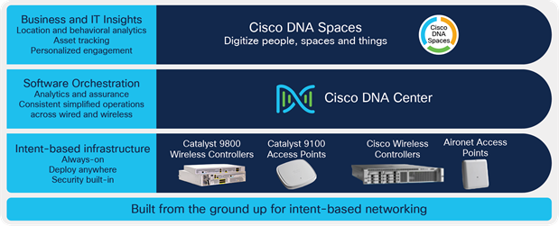
Cisco enterprise wireless solutions are resilient, have integrated security, and employ adaptive and insightful intelligence that provides useful insight into your network. With intent-based networking built on the Cisco Digital Network Architecture (Cisco DNA), Cisco enterprise wireless solutions go beyond the latest Wi-Fi 6 (802.11ax) standard and are ready for growing user expectations, IoT devices, and next-generation cloud-driven applications.
Cisco enterprise wireless solutions
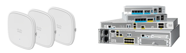
Cisco Catalyst 9800 Series Wireless Controllers: The Catalyst controllers streamline the best of RF excellence with open, programmable Cisco IOS XE Software benefits, meaning you no longer have two operating systems to manage. These modular, reliable, and highly secure controllers are flexible enough to deploy anywhere—including in your choice of cloud.
Cisco Catalyst 9100 Access Points: Going beyond the Wi-Fi 6 standard, the Catalyst 9100 access points provide integrated security, resiliency, and operational flexibility, as well as increased network intelligence. These access points extend Cisco’s intent-based network and scale to the growing demands of the Internet of Things (IoT) while fully supporting the latest innovations and newest technologies, making them perfect for organizations of all sizes.
Cisco Identity Services Engine (ISE): Cisco ISE allows you to provide highly secure network access to users and devices. It helps you gain visibility into what is happening in your network, such as who is connected, which applications are installed and running, and much more. It also shares vital contextual data, such as user and device identities, threats, and vulnerabilities, with integrated solutions from Cisco technology partners, so you can identify, contain, and remediate threats faster.
Cisco DNA Center: Cisco DNA Center can centrally manage major configuration and operations workflow areas.
● Design: Configures device global settings, network site profiles for physical device inventory, DNS, DHCP, IP addressing, software image repository and management, device templates, and user access.
● Policy: Defines business intent for provisioning into the network, including creation of virtual networks, assignment of endpoints to virtual networks, policy contract definitions for groups, and configuration of application policies.
● Provision: Provisions devices and adds them to inventory for management; supports Network Plug and Play; and creates fabric domains, control plane nodes, border nodes, edge nodes, fabric wireless, Cisco Unified Wireless Network wireless, transit, and external connectivity.
● Assurance: Enables proactive monitoring and insights to confirm that the user experience meets configured intent, using network, client, and application health dashboards, issue management, and sensor-driven testing.
● Platform: Allows programmatic access to the network and system integration with third-party systems using APIs, as well as feature set bundles, configurations, a runtime dashboard, and a developer toolkit.
For a complete overview and to learn more about Cisco enterprise wireless products and solutions, please visit the following page: https://www.cisco.com/c/en/us/products/wireless/index.html - ~resources
Cisco Catalyst 9800 Series Wireless Controllers based on Cisco IOS XE were introduced to the market at the end of 2018 with Cisco IOS XE Release 16.10.1. Since then, there have been constant innovations, new platform introductions, feature enhancements, and feature parity additions to make the Catalyst 9800 WLCs and the Catalyst 9100 access points the best in the enterprise-class market.
The following table provides the software versions validated within this deployment guide.
Table 1. Required minimum software versions
| Device |
Version |
| Cisco DNA Center |
2.2.3 or later |
| ISE |
3.1 or later with Advantage licenses (BYOD) ISE premier license (If MDM integration) |
| Catalyst 9800 Wireless Lan Controller |
Cisco IOS XE 17.6.1 or later with Cisco DNA Advantage licenses for APs |
| Cisco Wireless AP |
Cisco IOS XE 17.6.1 or later (11ac wave2 or 11ax APs) |
| MobileIron Cloud |
Compatible UEM solutions
*Validate with MobileIron Cloud and MS INtune
|
Note: MobileIron on-premises and Microsoft Intune are also supported.
Supports all modes of wireless controller (WLC) deployment: central, Cisco FlexConnect, and fabric.
Randomized and changing MAC (RCM) overview
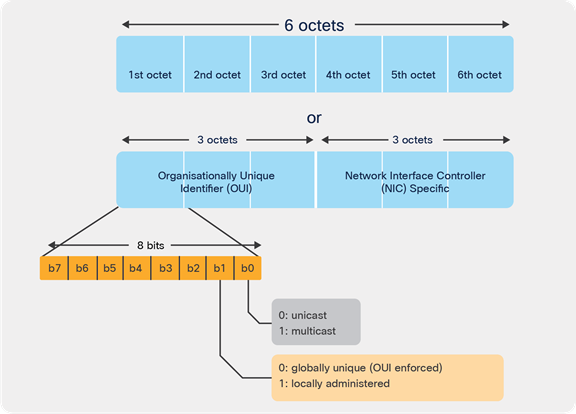
Historically, wireless clients have associated with a wireless network using the MAC address assigned during manufacture of the Wi-Fi Network Interface Card (NIC). This manufacturer-assigned MAC address, which is globally unique, is also known as the Burn-In Address (BIA). Use of this burn-in address everywhere raises the question of end-user privacy, as the end user can be tracked with the BIA. In this document, the BIA will be referred to as the normal MAC (address), in contrast to the random MAC (address).
To improve the privacy design of end-user products, various operating system vendors (Apple iOS 14, Android 10, and Windows 10) are enabling Wi-Fi operation using the locally administered MAC address (LAA); this will be referred as the random MAC (address).
Random MAC address or locally administered address
At first, the random MAC address was limited to probing for known wireless networks. This use has now been expanded to association to the wireless networks. Network policies that are keyed to the normal MAC address cannot be successfully applied to deliver the intended user experiences when the random MAC address is used for policy lookup. Some impacted use cases include MAC filtering, web-auth using MAC filtering, iPSK, static DHCP binding, Wi-Fi location, Cisco User Defined Network (UDN), etc.
There is neither an industry standard nor standardization activity addressing the concept of random MAC address use. It started with Apple, and since then Google and Microsoft have each come up with their own variation. Despite the communication channels with the abovementioned OS vendors, good documentation from OS vendors is not available. It will be necessary to remain vigilant regarding client behavior, as an OS vendor can change it at will.
Randomized and changing MAC on Wi-Fi devices
Mobile endpoints using random MAC addresses are nothing new. But the way they are used has changed since they were first introduced. In the beginning, devices used randomized MAC addresses to probe for known wireless networks. By randomizing the MAC address used in the probe request frame, devices were able to hide their real MAC address, thus providing some level of privacy. Fast-forward a few years, and devices started using random MAC addresses for associating to the wireless networks. This causes issues for network elements that rely on MAC addresses to uniquely identify the endpoint or the user behind it. The implementations of MAC randomization are different depending on the vendor, but here are a few examples of the behavior.
Microsoft Windows 10
● Can set up randomization both globally for all wireless connections or per network profile (SSID).
● Randomization is disabled by default out of the box.
● On the network profile, the user can also configure Windows 10 to generate a different random MAC address every day.
● Once a random MAC address is used for a given network profile, Windows 10 will keep using it as long as the user doesn't delete the network profile.
● If the user deletes the network profile, a different random MAC address will be used next time.
Google Android 10/11
● Can set up randomization per network profile (SSID).
● Randomization is enabled by default out of the box.
● Once a random MAC address is used for a given network profile, the device will keep using the same address even after the user deletes the network profile and re-creates the profile.
Apple iOS 14, iPadOS 14, watchOS 7
● Can set up randomization per network profile (SSID).
● Randomization is enabled by default out of the box.
● Once a random MAC address is used for a given network profile, the device will keep using the same address even after the user deletes the network profile and re-creates the profile.
● Randomization is enabled upon update to iOS 14 from previous versions of iOS for existing SSIDs.
RCM impact on the Wi-Fi network
The random MAC address is not known until the device connects to the network successfully (that is, until it has internet connectivity). Until then, it is likely that the device will change to a new random MAC address each time it tries to connect. This can affect different Wi-Fi deployment models, such as guest, BYOD, location analytics, etc. To help overcome problems with random MAC addresses, Cisco provides RCM solutions in multiple use cases.
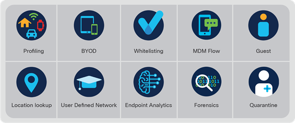
Use cases for RCM
Use cases for RCM
The following use cases can be implemented as part of an RCM solution.
● Random MAC identification: Identify the random MAC usage and provide visibility for easy detection of issues and troubleshooting on the WLC and Cisco DNA Center.
● RCM client access: Control the client join and access to a Wi-Fi network using RCM through the WLC and ISE.
● RCM network-wide usage tracking: Provide a view to filter and track overall RCM usage in the network through Cisco DNA Center.
● MDM/ISE BYOD integrations: Integration with Cisco and third-party Mobile Device Management (MDM) solutions to provide Extensible Authentication Protocol – Transport Layer Security (EAP-TLS) integration based on UniqueID. This requires WLC, ISE, and MDM.
● Track MAC change: Identify the same device using MDM EAP-TLS-based solutions, even after the MAC address has changed
● Guest solution with Cisco DNA Spaces: Use OpenRoaming to provide a seamless guest experience without dependency on a MAC address. This requires WLC and Cisco DNA Spaces.
Prerequisites for the RCM solution
1. Install or upgrade the Catalyst 9800 WLC to the 17.6.1 or later image.
2. Install or upgrade ISE to the 3.1 release.
3. If you have Cisco DNA Center, upgrade to the 2.2.3 version.
4. Have iOS 14+, Android 10+, and Windows 10 devices to test the RCM solution.
Prerequisites deployment
This process will take you through the steps necessary to set up your devices to be RCM solution ready, which entails ISE for authentication for BYOD/MDM workflows, while Cisco DNA Center is used for automation and assurance purpose.
These steps include integrating ISE and Cisco DNA Center, discovery of the Catalyst 9800 WLC, and creating network settings and a site hierarchy in Cisco DNA Center.
If you have already done these steps or do not intend to use ISE, MDM, and Cisco DNA Center, skip ahead to the Use Cases sections on WLAN deployment.
ISE and Cisco DNA Center integration
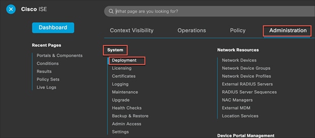
Step 1. Log in to the Cisco ISE Policy Administration Node (PAN) and navigate to Dashboard > ![]() > Administration > System > Deployment.
> Administration > System > Deployment.
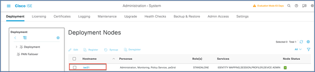
Step 2. Select the hostname of the ISE node.
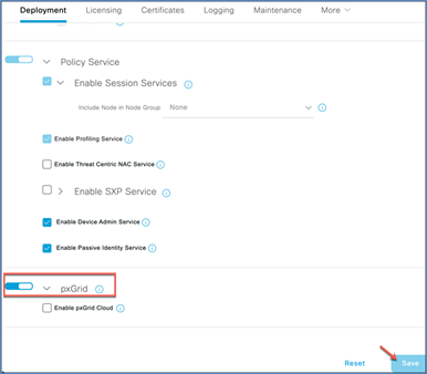
Step 3. Under General Settings, make sure the pxGrid checkbox is selected and click Save.
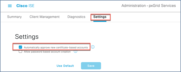
Step 4. Navigate to Administration > pxGrid Services > Settings.
Check “Automatically approve new certificate-based accounts,” and click Save.
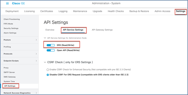
Step 5. Navigate to Administration > System > Settings > API Service Settings.
Enable ERS for Read/Write and click Save.
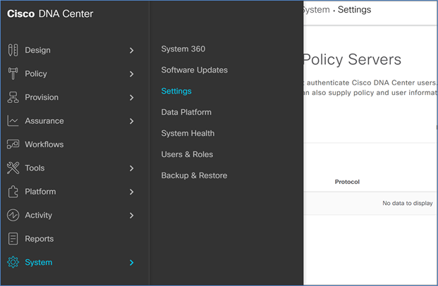
Step 6. Now log in to Cisco DNA Center and navigate to System > Settings.
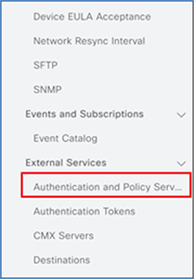
Step 7. Scroll down on the left and select Authentication and Policy Servers.
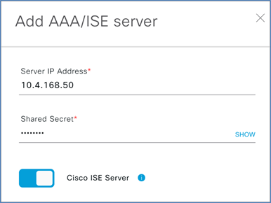
Step 8. Enter the ISE PAN management IP address and enter a shared secret. The shared secret is just an arbitrary secret you define to be used for pxGrid communication between ISE and Cisco DNA Center.
Step 9. Click the slider next to Cisco ISE Server.
Step 10. Enter the ISE admin credentials.
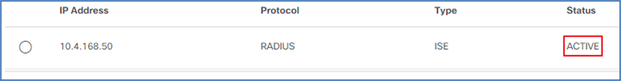
Step 11. Enter the Fully Qualified Domain Name (FQDN) for the Cisco ISE server.
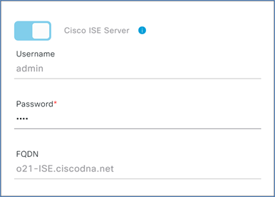
Step 12. Click Save and wait for the status to go from In Progress to Active.
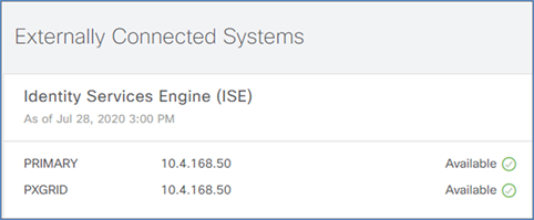
Step 13. Also ensure that ISE is listed as Available in Cisco DNA Center System 360 by navigating from the Cisco DNA Center menu to System > System 360 and scrolling down to Externally Connected Systems.
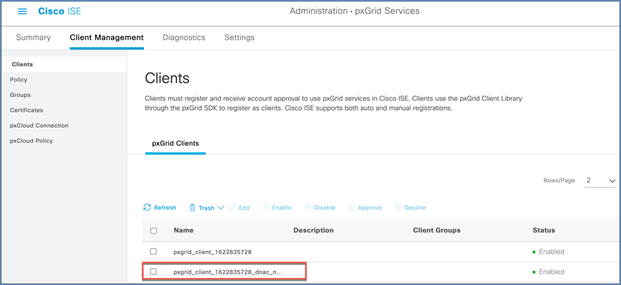
Step 14. In ISE navigate to Administration > pxGrid Services > Client Management, and see that your Cisco DNA Center subscriber name shows up.
Discover or add the Catalyst 9800 WLC to Cisco DNA Center
In this procedure we will go through the steps necessary to bring the Catalyst 9800 WLC into Cisco DNA Center’s inventory.
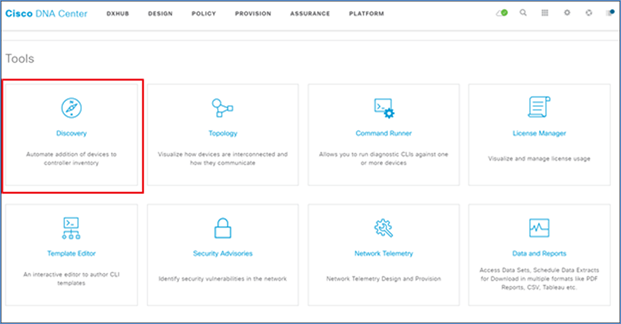
Step 1. Log in to Cisco DNA Center and select Discovery in the Tools section at the bottom of the homepage.
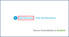
Step 2. Click Add Discovery.
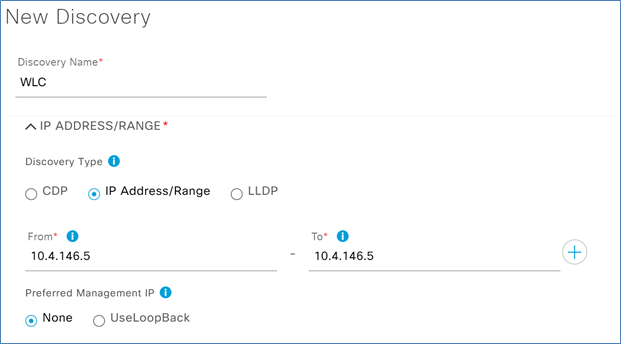
Step 3. Add a name for this discovery under Discovery Name.
Step 4. Under Discovery Type, select IP Address/Range and in the From – To section enter the management IP for the Catalyst 9800 WLC.
Note: Cisco WLCs must be discovered using the management IP. If they are not, the Wireless Controller 360 and AP 360 pages will not display data.
Step 5. Under Preferred Management, select one of the following options.
● None: Allows the device to use any of its IP addresses.
● Use Loopback: Specifies the device’s loopback interface as the management IP.
Step 6. Expand the Credentials section and click Add Credentials.
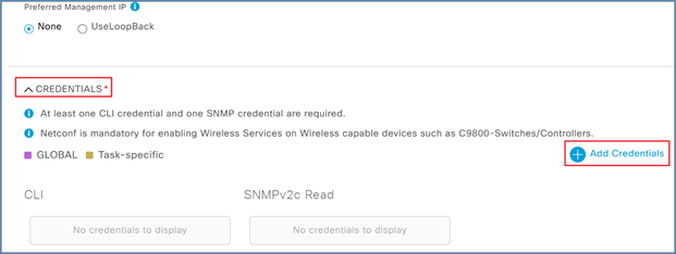
Step 7. In the CLI section enter the credentials needed to access the command-line interface of the device, and click Save.
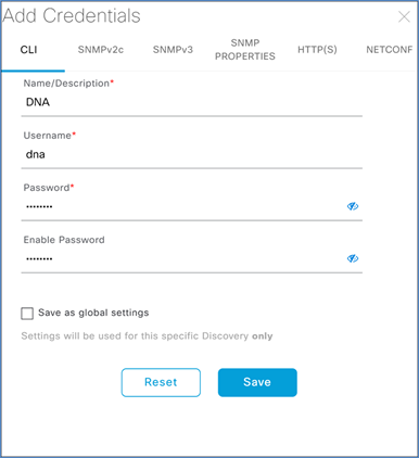
Note: Do not use "admin" as the username for your device CLI credentials. If you do, this can result in you not being able to log in to your devices.
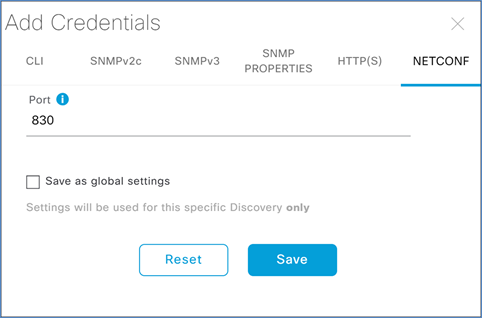
Step 8. Next, add the SNMP credentials that will be used to connect to the WLC.
Step 9. Click NETCONF, leave the default port of 830, and click Save.
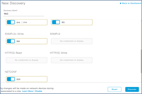
Step 10. Exit the Add Credentials menu by clicking the X in the top right corner.
Step 11. Check to make sure that all your credentials are set by checking the blue slider indicators, and then click Discover.
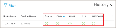
Step 12. After a few moments you should see your device discovered. Check the status indicators to make sure everything was discovered correctly.
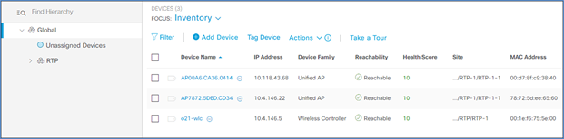
Step 13. Navigate to Provision > Inventory, and you should now see your WLC as well as any APs connected to the controller in your inventory.
Create a site hierarchy
Cisco DNA Center uses a network hierarchy of areas that contain subareas of buildings and floors. Devices are assigned to these buildings or floors and will then be provisioned depending on the network settings configured for that level.
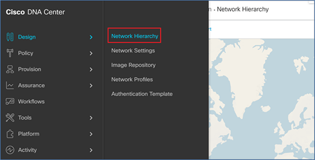
Step 1. In Cisco DNA Center, navigate to Designs > Network Hierarchy.
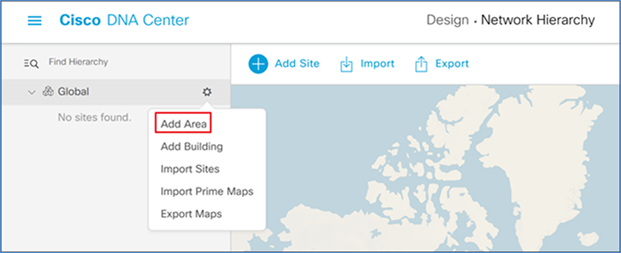
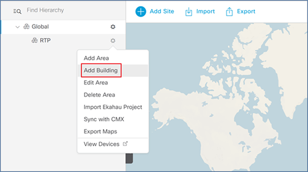
Step 2. Click the gear icon next to Global and select Add Area.
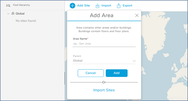
Step 3. In the resulting popup, enter your Area Name and click Add.
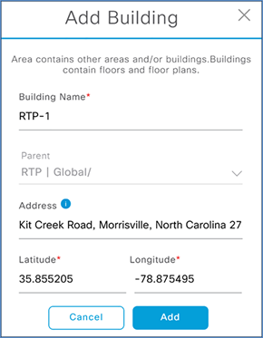
Step 4. Next to the newly created area, click the gear icon and select Add Building.
Step 5. In the resulting popup, enter the building name and address of your building. This will fill in the latitude and longitude automatically.
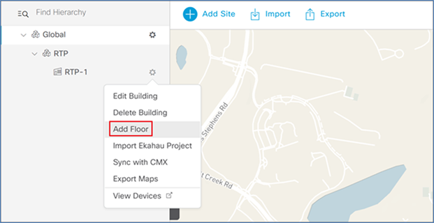
Step 6. Next to the newly added building, click the gear icon and select Add Floor.
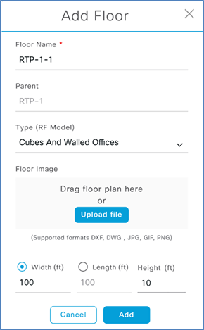
Step 7. Enter a floor name and click Add. Optionally, upload a floor plan.
Step 8. Repeat these steps for any additional sites, buildings, or floors in your environment.
Create network settings (optional if you only need assurance and monitoring)
These steps are required if the admin wants to configure and provision the Catalyst 9800 WLC from Cisco DNA Center with server settings.
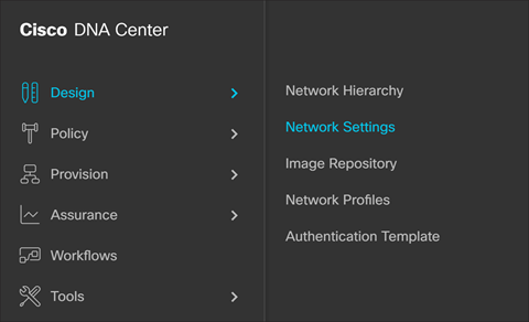
Step 1. In Cisco DNA Center, navigate to Design > Network Settings > Network.
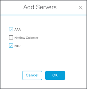
Step 2. Click Add Servers and select AAA and NTP and click OK.
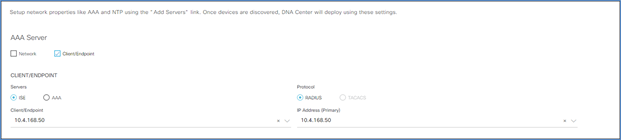
Step 3. Under AAA Server select the Client/Endpoint check box, and in the drop-down select the IP address for your ISE server.
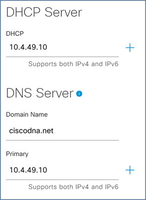
Step 4. Scroll down and enter the information for the DHCP and DNS servers.
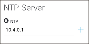
Step 5. Enter the information for the network NTP server and click Save.
Assign the WLC to a site
In this section, we will assign the Catalyst 9800 WLC to a site for getting assurance data.
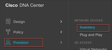
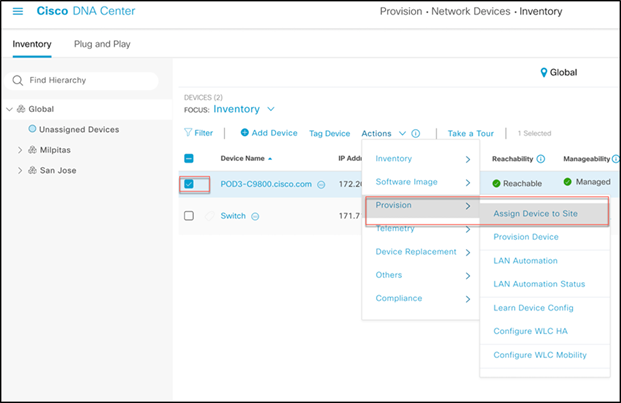
Step 1. In Cisco DNA Center, navigate to Provision > Inventory.
Step 2. Click the check box next to your WLC, and under Actions select Provision > Assign Device to Site.
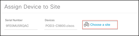
Step 3. In the resulting popup, click Choose a site to indicate where you would like to assign the WLC, and then click Save and Next.
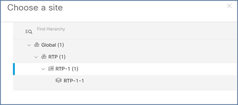
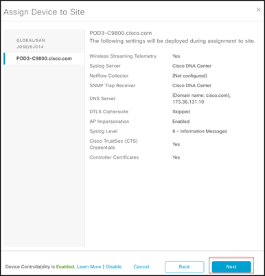
Step 4. In the screen that displays, double-check to make sure everything looks correct, and click Next.
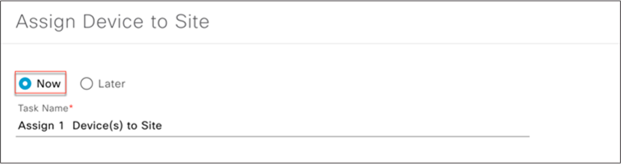
Step 5. Check Now and click Assign to add the WLC to the site.

After the devices are configured and added to Cisco DNA Center, you can perform the basic RCM use cases for the EFT.
Use case 1: Random MAC identification: Identifies random MAC usage and provides visibility for easy detection of issues and troubleshooting.
In Cisco IOS XE Release 17.5/17.6, the Catalyst 9800 WLC can categorize the device on the network using its universally administered address (BIA) or locally administered address (random changing MAC address), which helps the administrator to distinguish between the two MAC addresses.
This description assumes that the WLAN is preconfigured, or the user can create a new WLAN from the WLC or Cisco DNA Center.
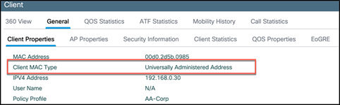
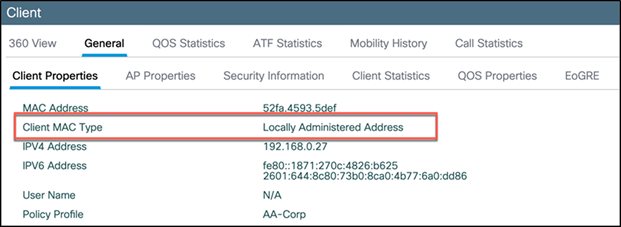
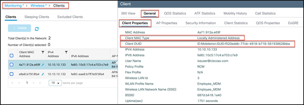
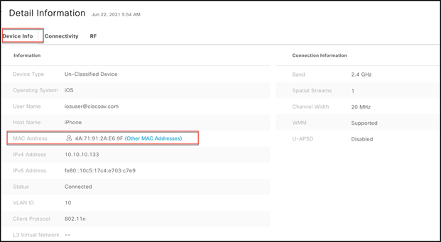
Connect some devices to that WLAN and then, from the WLC main menu, go to Monitoring > Wireless > Clients and click on the client. Go to the General tab and view the Client MAC Type, which will indicate if the device is using a universal or randomized MAC address.
Client using a universal MAC address
Client using a locally administered or randomized MAC address
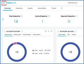
Enable RCM client visibility on Cisco DNA Center
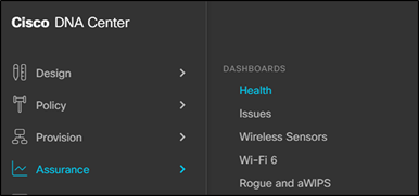
Step 1. Log in to Cisco DNA Center and navigate to Assurance > Health.
Step 2. Click Client.
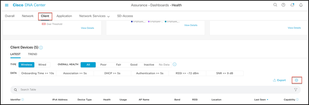
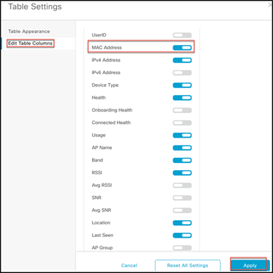
Step 3. Scroll down until you see the Client Devices section. Click the Table Settings button, then go to Edit Table Columns, enable MAC Address, and click Apply.
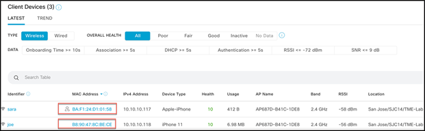
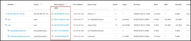
For devices using random MAC addresses, we have introduced a new icon ![]() in front of the device’s MAC address to symbolize RCM.
in front of the device’s MAC address to symbolize RCM.
Use case 2: RCM client access: Provides the ability to control the client joining a Wi-Fi network using a randomized changing MAC address.
Use case 2a: In Cisco IOS XE Catalyst 9800 Release 17.6, there is a new WLAN configuration option, “Deny LAA clients.” If this option is selected and checked, any client using a randomized changing MAC address (locally administered MAC address) will not be able to join that WLAN.
To use this feature, go to the particular WLAN on which you want to enable this option. Navigate to Configuration > Tags and Profiles > WLANs, select the WLAN, and under the Advanced tab select Deny LAA clients and click Update and Apply.
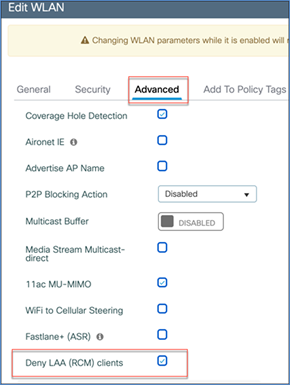
Try connecting a client to the WLAN with the “Deny LAA (RCM) clients” option enabled. The client should not be able to connect and should fail to join the network.
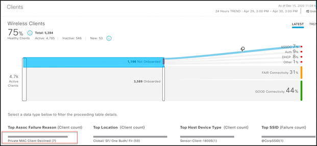
View RCM client failure on Cisco DNA Center
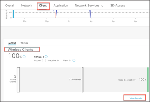
This association failure can be viewed in Cisco DNA Center by navigating to Assurance > Health > Client Wireless Clients > View Details. From there you can see, under Top Assoc Failure Reason, that the clients are declined due to the use of private or random MAC addresses.
Use case 2b: End users can be instructed to disable MAC randomization on the device before getting intended network access. This can be achieved by redirecting users to a modified hotspot page that provides instructions to disable MAC randomization when the device is using a random MAC address to connect to the network. Once MAC randomization is disabled, the user can connect normally.
Configuration
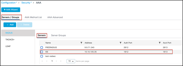
Step 1. Make sure the Catalyst 9800 WLC is added to ISE, and that ISE as AAA/RADIUS server is added to the Catalyst 9800.
On the Catalyst 9800, navigate to Configuration > Security > AAA > Servers/Groups > RADIUS and click Add. Add the RADIUS server as ISE.
Note: See the Catalyst 9800 and ISE Integration Reference guide: https://community.cisco.com/t5/security-documents/ise-and-catalyst-9800-series-integration-guide/ta-p/3753060
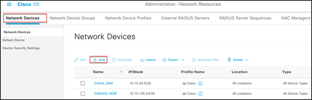
Similarly, on the ISE, add the WLC at Dashboard > Administration > Network Resources > Network Devices.
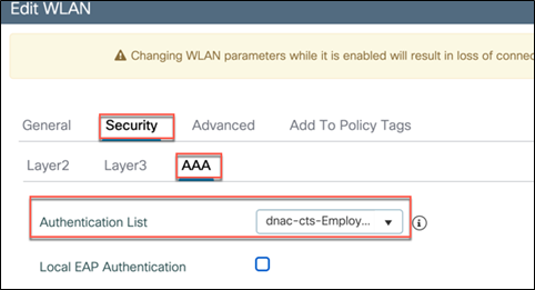
Also, the WLAN under test should be configured for AAA authentication. To do this, navigate to Configuration > Tags and Profiles > WLANs, click on the WLAN, and from Security > AAA select the RADIUS server from the drop-down Authentication List menu.
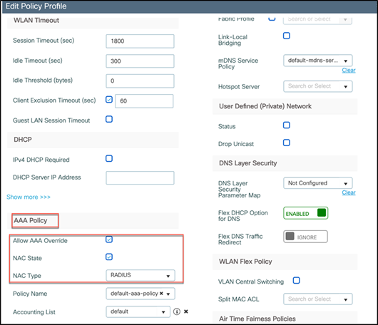
In addition, the policy profile used for the WLAN should have the Allow AAA Override and NAC State features enabled and the NAC Type set to RADIUS, as shown below.
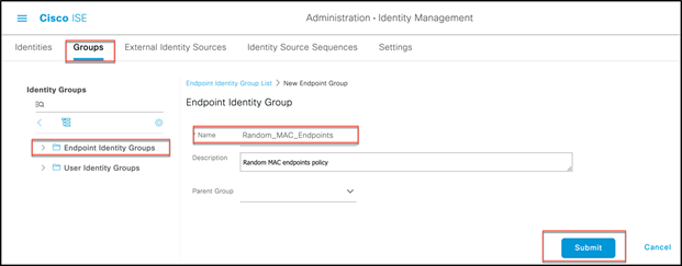
Step 2. From the ISE, navigate to Administration > Identity Management > Groups, select Endpoint Identity Groups, and select Add to create a new endpoint group called Random_MAC_Endpoints.
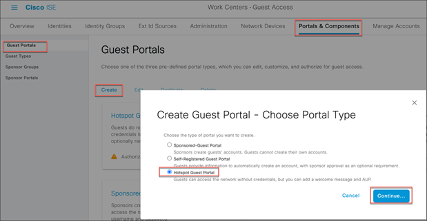
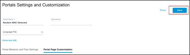
Step 3. Navigate to Work Centers > Guest Access > Portals and Components, select Guest portals, and select Create to create a new hotspot guest portal called Random MAC Detected.
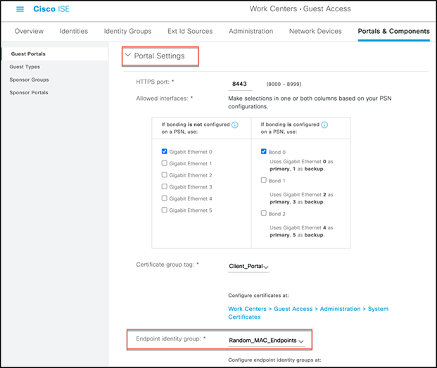
Step 4. Under Portal Settings, select the endpoint group created above for the Endpoint identity group.
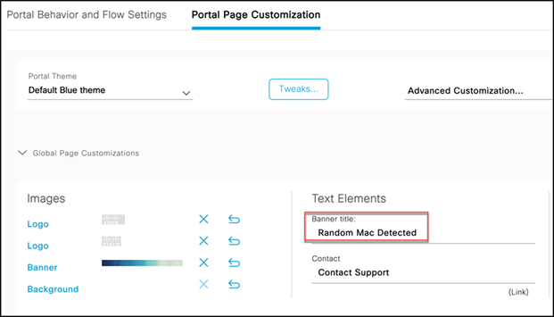
Step 5. Select Portal Page Customization.
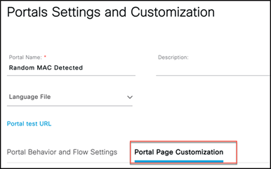
Step 6. Under Text Elements, change the banner title to Random MAC Detected.
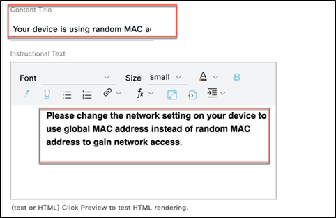
Step 7. Select Acceptable Use Policy.
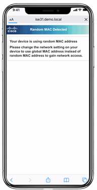
Step 8. Change Content Title to: Your device is using a random MAC address.
Step 9. Add the following text to the Instructional Text page:
Please change the network setting on your device to use a global MAC address instead of a random MAC address to gain network access.
Further instructions can also be provided with specifics on disabling MAC randomization per SSID or globally on the device.
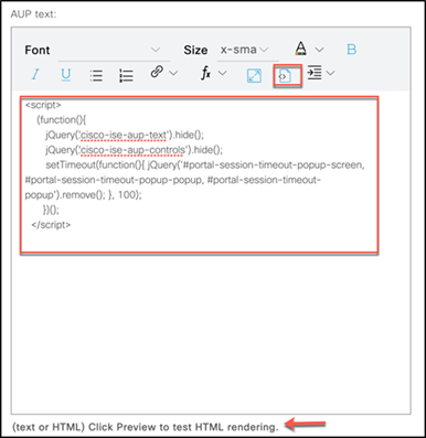
Step 10. Add the following optional content on the AUP text page to remove hotspot portal elements (make sure to select the Toggle HTML Source button before and after pasting in the script):
<script>
(function(){
jQuery('.cisco-ise-aup-text').hide();
jQuery('.cisco-ise-aup-controls').hide();
setTimeout(function(){ jQuery('#portal-session-timeout-popup-screen, #portal-session-timeout-popup-popup, #portal-session-timeout-popup').remove(); }, 100);
})();
</script>
Step 11. Other settings on this page can be changed to provide instructions for modifying the MAC randomization setting on the devices. Once you are done, select Save.
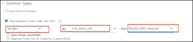
Step 12. Now create an authorization profile called Random_MAC_Detect to redirect to the page created above.
Under Web Redirection, select Hot Spot, configure the ACL name (which should be the same as the ACL on the Catalyst 9800 with deny and permit policies), and select the Value (Random MAC Detected) from the drop-down menu that you created earlier.
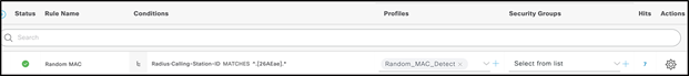
Step 13. Create an authorization policy rule to use Random MAC with a condition that matches any randomized MAC address for any SSIDs to deny random MAC addresses. Here, a regex string matching the condition (MATCHES ^.[26AEae].*) is used to identify random MAC addresses using a locally significant bit of the MAC address that both Android and iOS devices follow.
Step 14. Once the configurations are done, connect a client (iOS14+, Android 10, or Windows 10) using a random MAC address to the SSID under test. When connected and an RCM is detected, the redirection page will state that devices using random MAC addresses are not allowed on the network. Users can disable the random MAC address on their device and rejoin the network.
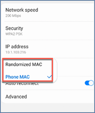
Device-specific instructions for disabling RCM
The following are steps that the user can be instructed to complete for some common devices. Vendors of specific devices could have slightly different steps for disabling MAC randomization on their devices.
Android:
1. Open the Settings app.
2. Select Network and Internet.
3. Select Wi-Fi.
4. Ensure that you are connected to the corporate SSID.
5. Tap the gear icon next to the current Wi-Fi connection.
6. Select Advanced.
7. Select Privacy.
8. Select Use Device MAC.
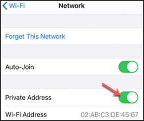
Apple:
Apple has published an article with instructions for disabling MAC randomization on their devices. See https://support.apple.com/en-us/HT211227.
Windows:
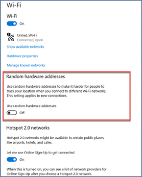
Randomized MAC addresses are disabled by default on Windows, but a user can choose to turn them on. Here are instructions for disabling the feature if enabled:
● Disable “Use random hardware addresses” for all networks:
1. Select the Start button, then select Settings > Network and Internet > Wi-Fi.
2. Set the slider to off under Use random hardware addresses.
● Disable “Use random hardware addresses” for a specific network:
1. Select the Start button, then select Settings > Network and Internet > Wi-Fi > Manage known networks.
2. Choose a network, then select Properties.
3. Under Use random hardware addresses for this network use the drop-down to select "Off."
Use case 3: RCM network-wide usage tracking: Provides a view to filter and track overall RCM clients in the network through Cisco DNA Center.
From Cisco DNA Center Assurance, navigate to Health > Client and scroll down to Client Devices, choosing the latest or trend view. You can filter the devices with MAC addresses, as a new RCM (Randomized and Changing MAC Address) filter has been added. Select it and click Apply.
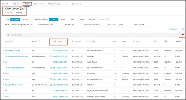
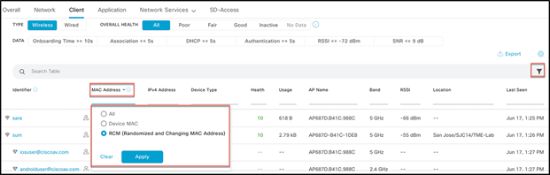
This will filter and show all the devices using RCM.
Use case 4: MDM/ISE BYOD integrations: Integrates with Cisco and third-party MDM solutions to provide EAP-TLS integration based on a Device Unique ID/Global Unique ID (DUID/GUID). Both of these terms can be used interchangeably.
The latest endpoint OSs randomize the device MAC address as they connect to the network. As a result, MDM compliance check and other security controls fail because of unrecognized random MAC addresses as device identifiers. The solution requires the integration of WLC, ISE, and MDM plus Cisco DNA Center for device visibility.
For this EFT we will be using the MobileIron MDM. The solution involves introducing a DUID/GUID into the certificate, which gets presented to the ISE during authorization. The ISE extracts this ID and maintains a mapping of ID to MAC address. The following data flow gives more information.
DUID/GUID data flow
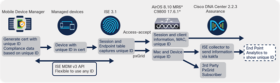
DUID/GUID data flow
● This solution relies on the mobile device manager, also referred to as a device manager or unified endpoint manager (for example, Cisco Meraki, Airwatch, Intune, MobileIron, etc.), which manage devices in an enterprise infrastructure.
● ISE provides the provisioning of the device with the unique ID-based (DUID) certificates.
● The device presents this certificate during TLS-based authentication. ISE authorizes the devices and also reads the unique ID from the certificate.
● The DUID is used for compliance check with MDM servers and also a unique identifier of the device in the endpoint table.
● The randomized MAC address will not matter, as now the device will have a DUID using the ID in the certificate.
● Since the ISE has the mapping of the DUID and the random MAC address, it can share this information in two ways:
◦ Through pxGrid as part of the session information, where Cisco DNA Center is the pxGrid subscriber.
◦ Through the WLC getting the client information from the ISE as part of VSA access-accept. This information is send to Cisco DNA Center.
Note: The solution requires integration of the ISE and MDM.
MDM interoperability with Cisco ISE
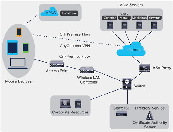
MDM servers secure, monitor, manage, and support mobile devices deployed across mobile operators, service providers, and enterprises. These servers act as policy servers that control the use of some applications on mobile devices (for example, email applications) in the deployed environment. However, the network is the only entity that can provide granular access to endpoints based on ACLs. Cisco ISE queries the MDM servers for the necessary device attributes to create ACLs that provide network access control for those devices.
You can run multiple active MDM servers on your network, including ones from different vendors. This allows you to route different endpoints to different MDM servers based on device factors such as location or device type.
Cisco ISE also integrates with MDM servers using the Cisco MDM Server Info API, Version 2, to allow devices to access the network over VPN via Cisco AnyConnect 4.1 and Cisco Adaptive Security Appliances 9.3.2 or later.
In the following illustration, Cisco ISE is the enforcement point and the MDM policy server is the policy information point. Cisco ISE obtains data from the MDM server to provide a complete solution.
Cisco ISE and MDM servers
You can configure Cisco ISE to interoperate with one or more external MDM servers. By setting up this type of third-party connection, you can use the detailed information available in the MDM database. Cisco ISE uses REST API calls to retrieve information from the external MDM server. It then applies the appropriate access control policies to switches, access routers, wireless access points, and other network access points. The policies give you greater control of the remote devices that are accessing the Cisco ISE-enabled network.
Cisco ISE performs the following functions with the external MDM server:
● Manages device registration: Unregistered endpoints that access the network are redirected to a registration page that is hosted on the MDM server. Device registration includes the user role, device type, and so on.
● Handles device remediation: Endpoints are granted restricted access during remediation.
● Augments endpoint data: The endpoint database is updated with information from the MDM server that you cannot gather using the Cisco ISE profiling services. Cisco ISE uses six device attributes that you can view in the Endpoints window. In the Cisco ISE GUI, click the Menu icon ![]() and choose Work Centers > Network Access > Identities > Endpoints.
and choose Work Centers > Network Access > Identities > Endpoints.
The following are examples of the device attributes available.
◦ MDMImei: 99 000100 160803 3
◦ MDMManufacturer: Apple
◦ MDMModel: iPhone
◦ MDMOSVersion: iOS 6.0.0
◦ MDMPhoneNumber: 9783148806
◦ MDMSerialNumber: DNPGQZGUDTF9
● Polls the MDM server once every four hours for device compliance data. Configure the polling interval in the External MDM Servers window. (To view this window, click the Menu icon ![]() and choose Work Centers > Network Access > Network Resources > External MDM Servers.
and choose Work Centers > Network Access > Network Resources > External MDM Servers.
When you configure an MDM server in Cisco ISE, the vendor's attributes are added to a new entry named mdm in the Cisco ISE system dictionary. The following attributes are used for registration status and are commonly supported by MDM vendors.
● DeviceRegisterStatus
● DeviceCompliantStatus
● DiskEncryptionStatus
● PinLockStatus
● JailBrokenStatus
● Manufacturer
● IMEI
● SerialNumber
● OsVersion
● PhoneNumber
● MDMServerName
● MDMServerReachable
● MEID
● Model
● UDID
If a vendor's unique attributes are not supported, you may be able to use ERS APIs to exchange vendor-specific attributes. Check the vendor's documentation for information on the ERS APIs supported.
Supported MDM servers include products from the following vendors:
● Absolute
● BlackBerry – BES
● BlackBerry – Good Secure EMM
● Cisco Meraki Systems Manager
● Citrix Endpoint Management (formerly Xenmobile)
● Globo
● IBM Security MaaS360
● Jamf Pro (formerly Jamf Casper Suite)
● Microsoft Intune, for mobile devices
● Microsoft System Center Configuration Manager (SCCM), for desktop devices
● Ivanti (formerly MobileIron) Unified Endpoint Management (UEM) (some versions of UEM do not work with Cisco ISE. Ivanti is aware of this problem and has a fix. Please contact Ivanti for more information.)
● Mosyle
● SAP Afaria
● Sophos
● SOTI MobiControl
● Symantec
● Tangoe
● VMware Workspace ONE (formerly AirWatch)
● 42Gears
ISE Community Resource:
How To: Meraki EMM / MDM Integration with ISE
The following table lists the ports that must be open between Cisco ISE and an MDM server to enable them to communicate with each other. See the documentation from the MDM vendor for a list of ports that must be open on the MDM agent and server
Table 2. Ports used by MDM servers
| MDM server |
Port |
| MobileIron |
443 |
| Zenprise |
443 |
| Good |
19005 |
| Workspace ONE |
443 |
| Afaria |
443 |
| MaaS360 |
443 |
| Meraki |
443 |
| Microsoft Intune |
80 and 443 |
| Microsoft SCCM |
80 and 443 |
Step 1. The user associates a device with an SSID.
Step 2. Cisco ISE makes an API call to the MDM server.
Step 3. This API call returns a list of devices for the user and the posture statuses for the devices.
Note: The input parameter is the MAC address of the endpoint device. For off-premises Apple iOS devices (any device that connects to Cisco ISE through a VPN), the input parameter is the UDID.
Step 4. If the user’s device is not on this list, it means that the device is not registered. Cisco ISE sends an authorization request to the Network Access Device (NAD) to redirect to Cisco ISE. The user is presented with the MDM server page.
Note: You must register a device that is enrolled on the MDM server outside of a Cisco ISE network via the MDM portal. This is applicable for Cisco ISE Release 1.4 and later. Earlier Cisco ISE versions allow devices that are enrolled outside the Cisco ISE-enabled network to be automatically enrolled if they are compliant with the posture policies.
Step 5. Cisco ISE uses MDM to provision the device and presents the appropriate window for the user to register the device.
Step 6. The user registers the device in the MDM server, and the MDM server redirects the request to Cisco ISE through automatic redirection or manual browser refresh.
Step 7. Cisco ISE queries the MDM server again for the posture status.
Step 8. If the user’s device is not compliant with the posture (compliance) policies that are configured on the MDM server, the user is notified that the device is out of compliance. The user must take the necessary action to ensure that the device is compliant.
Step 9. When the user’s device is compliant, the MDM server updates the device's state in its internal tables.
Step 10. If the user refreshes the browser now, the control is transferred back to Cisco ISE.
Step 11. Cisco ISE polls the MDM server once every four hours to get compliance information and issues the appropriate Change of Authorization (CoA). You can configure the polling interval. Cisco ISE also checks the MDM server every five minutes to make sure that it is available.
The following figure illustrates the MDM process flow.
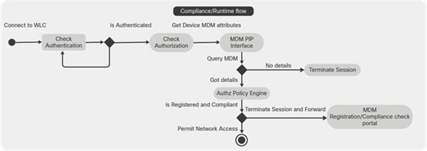
MDM process flow
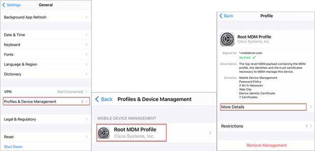
Note: A device can be enrolled in only a single MDM server at a time. If you want to enroll the same device to an MDM server from another vendor, the previous vendor's profiles must be removed from the device. The MDM server usually offers a "corporate wipe," which deletes only the vendor's configuration from the device (not the whole device). The user can also remove the files. For example, on an iOS device, the user can go to the Settings > General > Device Management window and click Remove Management. Or the user can go to the MyDevices portal in Cisco ISE and click Corporate Wipe.
Handle random and changing MAC addresses with an MDM server
To avoid issues caused by the use of the MAC address randomization method, configure Cisco ISE to identify endpoints that are connected to an MDM server by a unique device identifier instead of a MAC address. Mobile devices increasingly use random and changing MAC addresses for each SSID. This means that an endpoint presents different MAC addresses to the MDM server and to Cisco ISE. As a result, when the MDM server and Cisco ISE are integrated and an action is initiated for an endpoint, issues arise because the endpoint's identity is different in the two systems.
In Cisco ISE, you can now work around this problem by configuring Cisco ISE to use a unique device identifier instead of MAC addresses. When an endpoint enrolls with an MDM server, the MDM server sends a certificate with a GUID value to the endpoint. The endpoint uses this certificate for authentication with Cisco ISE. Cisco ISE receives the GUID for the endpoint from the certificate. All communications between Cisco ISE and the MDM server now use the GUID to identify the endpoint, helping ensure accuracy and consistency between the two systems.
Note that GUIDs are available only in certificate-based authentication methods. Basic authentication methods that use only a username and password will not be able to leverage the GUID-based solution.
The Cisco ISE MDM APIs have been updated (Cisco ISE MDM APIs Version 3) to facilitate the gathering and management of GUID data. Currently, MobileIron supports Cisco ISE MDM APIs Version 3, and sends GUID information to Cisco ISE.
Configure GUID for connected MDM servers
To check if an MDM server you have already connected to Cisco ISE supports the latest Cisco ISE MDM APIs and can send GUID information, carry out the following steps:
Step 1. In the Cisco ISE GUI, click the Menu icon ![]() and choose Administration > Network Resources > External MDM.
and choose Administration > Network Resources > External MDM.
Step 2. In the MDM Servers window, check the check box for the MDM server you want to test, and click Edit.
Step 3. Click Test Connection.
Step 4. If the MDM server supports Cisco ISE MDM APIs Version 3, a new section called Device Identifiers is displayed.
Check the check boxes to enable one or more of the following options:
● Cert - CN, GUID
● Cert - CN, Hostname
● Cert - SAN DNS, GUID
● Cert - SAN DNS, Hostname
● Legacy MAC Address
You can drag and drop the options to organize them in the order of preference. For example, if you place Cert -SAN DNS, GUID first and then Cert -SAN DNS, Hostname, Cisco ISE will first query the MDM server for the SAN DNS and GUID attributes of an endpoint. If the requested attributes are not available, it will query for the SAN DNS and Hostname attributes of the endpoint.
Step 5. Click Save.
Sharing GUID through pxGrid
Cisco ISE can share this GUID information through pxGrid with other Cisco solutions. You can share the GUID received from MDM servers with a Cisco DNA Center in your deployment through pxGrid topics.
Set up MDM servers with Cisco ISE
To set up MDM servers with Cisco ISE, you must perform the following high-level tasks:
Step 1. Import the MDM server certificate into Cisco ISE, except for Intune, where you import the Policy Administration Node's (PAN) certificate into Azure.
Step 2. Create mobile device manager definitions.
Step 3. Configure ACLs on the wireless LAN controllers.
Step 4. Configure an authorization profile that redirects nonregistered devices to the MDM server.
Step 5. If there are multiple MDM servers on the network, configure a separate authorization profile for each vendor.
Step 6. Configure authorization policy rules for the MDM use cases.
Import the MDM server certificate into Cisco ISE
For Cisco ISE to connect with the MDM server, you must import the MDM server certificate into the Cisco ISE Trusted Certificates store. If your MDM server has a CA-signed certificate, you must import the root certificate into the Cisco ISE Trusted Certificates store.
Step 1. Export the MDM server certificate from your MDM server and save it on your local machine.
Step 2. In the Cisco ISE GUI, click the Menu icon ![]() and choose Administration > System > Certificates > Trusted Certificate > Import.
and choose Administration > System > Certificates > Trusted Certificate > Import.
Step 3. In the Import a New Certificate into the Certificate Store window, click Choose File to select the MDM server certificate that you obtained from the MDM server.
Step 4. Add a name for the certificate in the Friendly Name field.
Step 5. Check the Trust for authentication within ISE check box.
Step 6. Click Submit.
Step 7. Verify that the Trusted Certificates window lists the newly added MDM server certificate.
Define device management servers in Cisco ISE
Define mobile and desktop device management servers in Cisco ISE to allow Cisco ISE to communicate with the required servers. You can configure the authentication type used to communication with the servers, the frequency with which Cisco ISE requests device information from a device management server, and so on.
Configure MDM servers in Cisco ISE
Step 1. In the Cisco ISE GUI, click the Menu icon ![]() and choose Administration > Network Resources > External MDM.
and choose Administration > Network Resources > External MDM.
Step 2. In the MDM Servers window, click +Add.
Step 3. Enter the name and description of the MDM server that you want to add in the corresponding fields.
Step 4. From the Server Type drop-down list, choose Mobile Device Manager.
Step 5. From the Authentication Type drop-down list, choose either Basic or OAuth- Client credentials. If you choose the Basic authentication type, the following fields are displayed:
● Host Name / IP Address: Enter the hostname or IP address of the MDM server.
● Port: Enter the port to use when connecting to the MDM server, which is usually 443.
● Instance Name: If this MDM server has several instances, enter the instance that you want to connect to.
● Username: Enter the username that must be used to connect to the MDM server.
● Password: Enter the password that must be used to connect to the MDM server.
● Polling Interval: Enter the polling interval in minutes for Cisco ISE to poll the MDM server for compliance check information. Set this value to match the polling interval on your MDM server. The valid range is from 15 to 1440 minutes. The default value is 240 minutes. We recommend that you set the polling interval below 60 minutes only if you are testing a few active clients on your network. If you set this value below 60 minutes for a production environment with many active clients, the system’s load increases significantly and may negatively affect performance.
If you set the polling interval to 0, Cisco ISE disables communication with the MDM server.
● Time Interval for Compliance Device ReAuth Query: When an endpoint is authenticated or reauthenticated, Cisco ISE uses a cache to get the MDM variables for that endpoint. If the age of the cached value is higher than the value configured in this field, Cisco ISE sends a new device query to the MDM server to get new values. If the compliance status has changed, Cisco ISE triggers the appropriate CoA.
The valid range is from 1 to 1440 minutes. The default value is 1 minute.
If you choose the OAuth - Client Credentials authentication type, the following fields are displayed:
● From the Auto Discovery drop-down list, choose Yes or No.
● Auto Discovery URL: Enter the value of the Microsoft Azure AD Graph API Endpoint from the Microsoft Azure management portal. This URL is the endpoint at which an application can access directory data in your Microsoft Azure AD using the Graph API. The URL is of the form: https://<hostname>/<tenant id>. For example, https://graph.windows.net/47f09275-5bc0-4807-8aae-f35cb0341329.
An expanded version of this URL is also in the property file and is of the form: https://<Graph_API_Endpoint>/<TenantId_Or_Domain>/servicePrincipalsByAppId/<Microsoft Intune AppId>/serviceEndpoints?api-version=1.6 and client-request-id=<Guid.NewGuid()>
● Client ID: The unique identifier for your application. Use this attribute if your application accesses data in another application, such as the Microsoft Azure AD Graph API, Microsoft Intune API, and so on.
● Token Issuing URL: Enter the value of the OAuth2.0 Authorization Endpoint from the previous step. This is the endpoint at which the application obtains an access token using OAuth2.0. After the application is authenticated, Microsoft Azure AD issues the application (Cisco ISE) an access token, which allows the application to call the Graph API or Intune API.
● Token Audience: The recipient resource that the token is intended for, which is a public, well-known APP ID URL to the Microsoft Intune API.
● Polling Interval: Enter the polling interval in minutes for Cisco ISE to poll the MDM server for compliance check information. Set this value to match the polling interval on your MDM server. The valid range is from 15 to 1440 minutes. The default value is 240 minutes. We recommend that you set the polling interval below 60 minutes only if you are testing a few active clients on your network. If you set this value below 60 minutes for a production environment with many active clients, the system’s load increases significantly and may negatively affect performance.
If you set the polling interval to 0, Cisco ISE disables communication with the MDM server.
● Time Interval for Compliance Device ReAuth Query: When an endpoint is authenticated or reauthenticated, Cisco ISE uses a cache to get the MDM variables for that endpoint. If the age of the cached value is higher than the value configured in this field, Cisco ISE sends a new device query to the MDM server to get new values. If the compliance status has changed, Cisco ISE triggers the appropriate CoA.
The valid range is from 1 to 1440 minutes. The default value is 1 minute.
Step 6. Choose Enabled from the Status drop-down list.
Step 7. To verify that the MDM server is connected to Cisco ISE, click Test Connection. Test Connection is not intended to check permissions for all the use cases (get baselines, get device information, and so on). These are validated when the server is added to Cisco ISE.
If the MDM server you are configuring supports Cisco ISE MDM API Version 3 and can share the attribute GUID with Cisco ISE, the Device Identifiers area is displayed. See the earlier section “Handle Random and Changing MAC Addresses with an MDM Server.”
Check the check boxes for one or more of the following options you want to enable, and arrange them in the order of preference by dragging and dropping each option in its place:
● Cert - CN, GUID
● Cert - CN, Hostname
● Cert - SAN DNS, GUID
● Cert - SAN DNS, Hostname
● Legacy MAC Address
Step 8. Click Save.
Connect Ivanti (previously MobileIron) Unified Endpoint Management server to Cisco ISE
Note: MobileIron has been acquired by Ivanti. This Unified Endpoint Management (UEM) solution was referred to as MobileIron Cloud at the time of the writing of this document. For more information, see the official documentation of Ivanti and MobileIron.
Cisco ISE leverages existing certificate-based authentication configurations to connect to MobileIron servers and receive GUID values from these servers. Cisco ISE then uses the GUID values instead of MAC addresses to identify endpoints, enabling reliable authentication even when MAC address randomization is in use.
GUID-based authentication occurs through the use of server certificates. With the following series of tasks, you configure the certificates sent from MobileIron servers to Cisco ISE to include GUID values.
In the MobileIron Cloud portal:
1. Create a user account and assign the Cisco ISE Operations role to it.
2. Configure a certificate authority.
3. Configure an identity certificate to include GUID information.
4. Upload root or trusted certificates as required.
5. Configure a Wi-Fi profile.
In Cisco ISE:
1. Upload the certificate generated in MobileIron Cloud to Cisco ISE.
2. Connect MobileIron servers to Cisco ISE.
Note: If you have already connected MobileIron servers to your Cisco ISE and want to receive GUIDs from the connected servers, carry out steps 3, 4, and 5, as required.
Create a MobileIron Cloud user account and assign the Cisco ISE Operations role
Step 1. Log in to the MobileIron Cloud portal.
Step 2. From the top menu, choose Users.
Step 3. Click Add and choose Add API User from the drop-down list.
Step 4. In the Add API User window, enter the values for the following fields:
● Username
● Email Address
● First Name
● Last Name
● Password
● Confirm Password
Step 5. To allow a user to invoke the APIs required for Cisco ISE integration, in the Assign Roles area, check the Cisco ISE Operations check box.
Step 6. Click Done.
Configure a certificate authority in MobileIron Cloud
This task takes you through configuring a local CA. However, MobileIron Cloud offers a wider range of CA configurations, and you must choose the option that best suits your organization’s requirements.
For information on the various types of certificate management supported by MobileIron Cloud, see http://mi.extendedhelp.mobileiron.com/75/all/en/Welcome.htm#LocalCertificates.htm?Highlight=certificate%20authority.
Step 1. In the MobileIron Cloud portal, choose Admin > Certificate Management.
Step 2. Click Add.
Step 3. Choose Create a Standalone Certificate Authority.
Step 4. In the dialog box that is displayed, enter the required details in the following fields:
a. Name
b. In the Subject Parameters area, enter a value for at least one of the following fields:
◦ Common Name
◦ Organization Unit
◦ Organization
◦ Street Address
◦ City
◦ Region
◦ Country
c. In the Key Generation Parameters area:
1. Key Type: Choose RSA from the drop-down list.
2. Signature Algorithm: Choose SHA256 with RSA from the drop-down list.
3. Key Length: Choose 2048 from the drop-down list.
Configure an identity certificate in MobileIron Cloud
Configure an identity certificate in MobileIron Cloud to define the certificate authentication mechanism for mobile devices. Identity certificates are X.509 certificates (.p12 or .pfx files). You can also generate identity certificates dynamically using a certificate authority as the source.
Note: If you have existing identity certificates in MobileIron Cloud that are configured for Cisco ISE MDM use cases, modify the certificate according to Step 6 of this task to receive GUID information from MobileIron servers.
Step 1. From the MobileIron Cloud top menu, choose Configurations and click Identity Certificate.
Step 2. In the Name field, enter a value.
Step 3. In the Configuration Setup area, choose Dynamically Generated from the drop-down list.
Step 4. From the Source drop-down list, choose the CA that you configured earlier.
Step 5. In the Subject Alternative Name Type field, choose Uniform Resource Identifier from the drop-down list.
In the Subject Alternative Name Value field, enter ID:Mobileiron:${deviceGUID}. We recommend that you configure the Subject Alternative Name Value field for the GUID.
Alternatively, to use the Common Name field to push the GUID to Cisco ISE, in the Subject field, enter CN=ID:Mobileiron:${deviceGUID}.
Step 6. Click Test Configuration and Continue.
The Configuration Test Successful dialog box displays the details of the identity certificate created.
Step 7. In the Distribute window, click Custom.
Step 8. In the Define Device Group Distribution area, check the check boxes for the device groups you want to distribute in this configuration.
Step 9. Click Done.
If you update the SAN or CN fields in an existing identity certificate for Cisco ISE MDM use cases, the updated certificates must be sent to the end users connected to your network. To send the updated certificates to end users, in the Configurations > Choose Config > Edit window, check the following check box:
Clear cached certificates and issue new ones with recent updates
Upload root or trusted certificates in MobileIron Cloud
If you use a trusted third-party CA to generate identity certificates, you can ignore this task. If you use the local MobileIron Cloud CA or an internal CA that is private to your company or organization, you must upload the root certificate of the CA so that it is distributed to the connected devices. This allows the devices to trust the source or issuer of the identity certificate that is used for authentication.
Step 1. From the MobileIron Cloud menu, choose Configurations.
Step 2. Click Add and click Certificate.
Step 3. In the Name field, enter a name for the trusted certificate.
Step 4. In the Configuration Setup area, click Choose File. Choose the trusted or root certificate for your CA.
Step 5. Click Next.
Configure a Wi-Fi profile
Step 1. From the MobileIron Cloud menu, choose Configurations and click Wi-Fi.
Step 2. In the Name field, enter a value.
Step 3. In the Service Set Identifier (SSID) field, enter the name of your network.
Step 4. The Auto Join check box is checked by default. Allow this option to remain enabled.
Step 5. From the Security Type drop-down list, choose the required option.
Step 6. In the Enterprise Settings area, in the Protocols tab, check the TLS check box.
Step 7. In the Authentication tab, enter the required values in the Username and Password fields.
Step 8. From the Identity Certificate drop-down list, choose the identity certificate that you created
Step 9. (Optional) In the Trust tab, check the check box for the trusted certificate you want to use.
Step 10. In the All Versions area, from the Network Type drop-down list, choose Standard.
Step 11. Click Next.
Step 12. In the Distribute window, click the required option.
Step 13. In the Define Device Group Distribution area, check the check boxes for the device groups you want to include in this configuration.
Step 14. Click Done.
Configure an authorization profile for redirecting nonregistered devices
You must configure an authorization profile in Cisco ISE to redirect nonregistered devices for each external MDM server.
Before you begin
● Ensure that you have created an MDM server definition in Cisco ISE. Only after you successfully integrate Cisco ISE with the MDM server is the MDM dictionary populated. You can then create an authorization policy using the MDM dictionary attributes.
● Configure ACLs on the wireless LAN controller for redirecting nonregistered devices.
● If you are using a proxy for internet connection and the MDM server is part of the internal network, you have to put the MDM server name or its IP address in the Proxy-Bypass list.
In the Cisco ISE GUI, click the Menu ![]() icon and choose Administration > System > Settings > Proxy to perform this action.
icon and choose Administration > System > Settings > Proxy to perform this action.
Step 1. In the Cisco ISE GUI, click the Menu icon ![]() and choose Policy > Policy Elements > Results > Authorization> Authorization Profiles > Add.
and choose Policy > Policy Elements > Results > Authorization> Authorization Profiles > Add.
Step 2. Create an authorization profile for redirecting nonregistered devices that are not compliant or registered.
Step 3. In the Name field, enter a name for the authorization profile that matches the MDM server name.
Step 4. Choose ACCESS_ACCEPT from the Access Type drop-down list.
Step 5. In the Common Tasks section, check the Web Redirection check box and choose MDM Redirect from the drop-down list.
Step 6. Choose the name of the ACL that you configured on the wireless LAN controller from the ACL drop-down list.
Step 7. Choose the MDM portal from the Value drop-down list.
Step 8. Choose the MDM server that you want to use from the MDM Server drop-down list.
Step 9. Click Submit.
Configure authorization policy rules for the MDM use cases
You must configure authorization policy rules in Cisco ISE to complete the MDM configuration.
Before you begin
● Add the MDM server certificate to the Cisco ISE certificate store.
● Ensure that you have created the MDM server definition in Cisco ISE. Only after you have successfully integrated Cisco ISE with the MDM server does the MDM dictionary get populated. You can then create an authorization policy using the MDM dictionary attributes.
● Configure ACLs on the wireless LAN controller for redirecting nonregistered or noncompliant devices.
Step 1. In the Cisco ISE GUI, click the Menu ![]() icon and choose Policy > Policy Sets. Expand the policy set to view the authorization policy rules.
icon and choose Policy > Policy Sets. Expand the policy set to view the authorization policy rules.
Step 2. Add the following rules:
● MDM_Un_Registered_Non_Compliant: For devices that are not yet registered with an MDM server or are noncompliant with MDM policies. Once a request matches this rule, the Cisco ISE MDM window is displayed to the user, with information on registering the device with the MDM server.
Note: Do not use the MDM.MDMServerName condition in this policy. When this condition is used, an endpoint matches the policy only if the endpoint is registered with the MDM server.
● PERMIT: If the device is registered with Cisco ISE, is registered with MDM, and is compliant with Cisco ISE and MDM policies, it is granted access to the network based on the access control policies configured in Cisco ISE.
Step 3. Click Save.
Configuring ACLs on the wireless LAN controller for MDM interoperability
You must configure ACLs on the wireless controller for use in an authorization policy to redirect nonregistered devices and certificate provisioning. Your ACLs must be configured in the following sequence.
Step 1. Allow all outbound traffic from the server to the client.
Step 2. (Optional) Allow Internet Control Message Protocol (ICMP) inbound traffic from the client to the server for troubleshooting.
Step 3. Allow access to the MDM server for nonregistered and noncompliant devices to download the MDM agent and proceed with compliance checks.
Step 4. Allow all inbound traffic from the client to the server to Cisco ISE for the web portal and supplicant and certificate provisioning flows.
Step 5. Allow inbound DNS traffic from the client to the server for name resolution.
Step 6. Allow inbound DHCP traffic from the client to the server for IP addresses.
Step 7. Deny all inbound traffic from the client to the server to corporate resources for redirection to Cisco ISE (as per your company policy).
Step 8. (Optional) Permit the rest of the traffic.
Verify client MDM flow
For the MobileIron MDM use case, the user can install the MobileIron Go app on the mobile device and log in with their corporate credentials. Connect an iOS14 or Android device to a WLAN that is configured for MDM. It will ask to download and install a certificate and an MDM profile that has the information for the WLAN to which the user wants to connect.
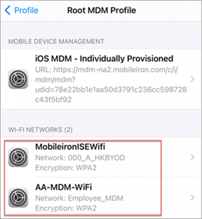
Go to WLC Monitoring > Wireless > Clients and verify that the client is connected to the correct WLAN and that a GUID/DUID is being created.
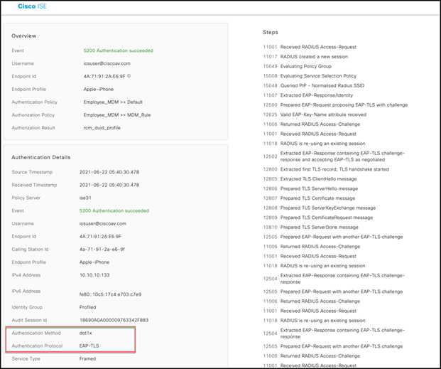
Similarly, the user can verify this on the ISE live logs by going to Dashboard > Operations > RADIUS > live logs and then selecting the endpoint to see the authentications details showing that the authentication protocol is EAP-TLS.
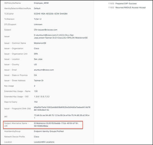
In addition, Other Attributes clearly shows the DUID as a SAN field.
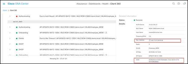
Similarly, the user can see the client DUID and random MAC address in Cisco DNA Center as well.
ISE DUID through BYOD workflow
The same use case can be implemented through ISE as part of a BYOD workflow, as ISE can generate a DUID during the BYOD process. BYOD can be deployed for a single SSID or dual SSIDs.
In general, we recommend that you minimize the number of SSIDs. Also, for the RCM EFT you must use a single SSID if the guest access is using a hotspot, as the open SSID cannot be using a hotspot portal for the initial BYOD portal at the same time. With single-SSID BYOD, the endpoint associates to a secure WLAN, gets onboarded, and then, after the endpoint automatically reconnects, is granted full network access via the same WLAN.
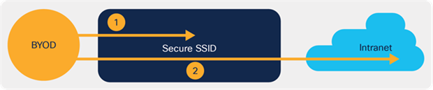
Single SSID BYOD workflow
For more prescriptive details and to gain an understanding of BYOD workflows, refer to the Cisco ISE BYOD Prescriptive Deployment Guide
Catalyst 9800 Series RCM configuration: https://www.cisco.com/c/en/us/td/docs/wireless/controller/9800/17-5/config-guide/b_wl_17_5_cg/m_knob_disable_random_mac_clients.html
What’s New in ISE 3.1 webinar, with RCM demo: https://www.youtube.com/watch?v=l_DmGF237wc&t=2053s