Cisco Catalyst 9136 Series Access Points Deployment Guide
Available Languages
Bias-Free Language
The documentation set for this product strives to use bias-free language. For the purposes of this documentation set, bias-free is defined as language that does not imply discrimination based on age, disability, gender, racial identity, ethnic identity, sexual orientation, socioeconomic status, and intersectionality. Exceptions may be present in the documentation due to language that is hardcoded in the user interfaces of the product software, language used based on RFP documentation, or language that is used by a referenced third-party product. Learn more about how Cisco is using Inclusive Language.
- US/Canada 800-553-2447
- Worldwide Support Phone Numbers
- All Tools
 Feedback
 Feedback
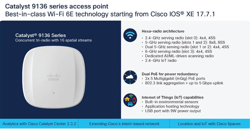
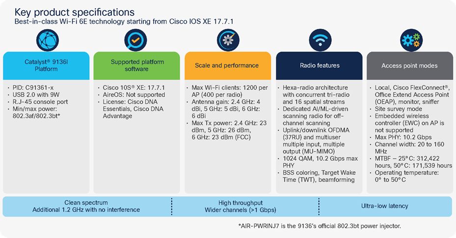
The Cisco® Catalyst® 9136I Access Point is Cisco’s first high-end Wi-Fi 6E wireless platform with a hexa-radio architecture, providing the full capability of 802.11ax such as orthogonal frequency-division multiple access (OFDMA), multiuser multiple-input multiple-output (MU-MIMO), Target Wake Time, BSS Coloring, overlapping BSS packet detection (OBSS-PD), and Wi-Fi Protected Access 3 (WPA3), all while being able to leverage advanced RF visibility with Cisco CleanAir® Pro together with an artificial intelligence and machine learning (AI/ML)-driven scanning radio. The Catalyst 9136I supports the entire Cisco Catalyst wireless stack functionality with Cisco Catalyst Center (Automation and Assurance), Cisco Spaces (Location and IoT), Identity Services Engine (security), and more. Throughout this guide, you will learn how the Catalyst 9136I is a wireless powerhouse that can take your network to the next level.
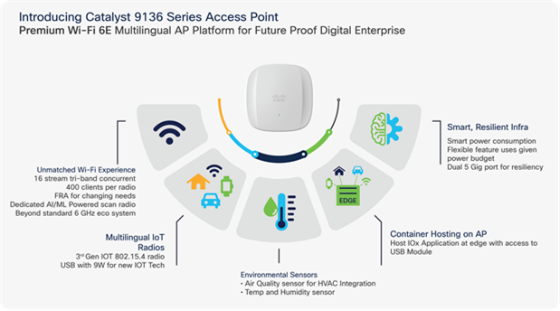
Key features of the Cisco Catalyst 9136I
Table 1. Supported Cisco IOS® XE Software
| Catalyst 9800 Series Wireless Controller software release |
| 17.7.1 and later |
Recommendation: The suggested release for the Catalyst 9136I is 17.8.1, since more features will be available.
Supported Controller platforms
Catalyst 9136I APs are supported with the following Catalyst 9800 Series Controllers:
● 9800-L
● 9800-CL
● 9800-40
● 9800-80
Note: Embedded wireless controller on AP (EWC) functionality is not supported on the Catalyst 9136, as either an active EWC or a subordinate AP. The AP can technically still join, but will not function properly.
Table 2. Catalyst 9136I at a glance
| Capability |
Catalyst 9136I Access Point |
| Product ID |
C9136I-x |
| Scale |
1200 clients total (400 clients per radio*) |
| Serving radios |
● 2.4 GHz (Slot 0), 4x4, 4 spatial streams (SS)
● 5 GHz (Slots 1 and 2), 8x8, 8SS
● 5 GHz (Slot 1 or 2), dual 4x4, 4SS (roadmap)
● 6 GHz (Slot 3), 4x4, 4SS
|
| IoT radio |
2.4 GHz (BLE 5) |
| Scanning radio |
Yes |
| Wi-Fi 6E/6 Features |
MU-MIMO, OFDMA |
| LAN port |
2x PoE-IN Multigigabit |
| Ports |
mGig0, mGig1, console |
| Antenna |
Integrated |
| Dimensions |
9.9 x 9.9 x 2.2 in (25.1 x 25.1 x 5.6 cm) |
| USB |
Yes, 9W output |
| Weight |
3.5 lb (1.59 kg) |
| Clients |
400 per radio (1200 per AP) |
| SSIDs |
2.4 GHz: 16; 5 GHz: 16; 6 GHz: 8 |
| MTBF |
25°C: 312,422 hours, 50°C: 171,539 hours |
*Note: When dual 5 GHz is released, the 1200 client max will still apply and will not be increased to 1600.
Table 3. Serving radio specifications
| Mode |
2.4 GHz Slot 0 |
5 GHz (primary) Slot 1 |
5 GHz (secondary) Slot 2 |
6 GHz Slot 3 |
| 1. Tri-radio 16SS |
4x4:4SS (20 MHz) |
8x8:8SS (20/40/80 MHz) |
N/A |
4x4:4SS (20/40/80/160 MHz) |
| 2. Tri-radio 12SS |
4x4:4SS (20 MHz) |
4x4:4SS (20/40/80/160 MHz) |
N/A |
4x4:4SS (20/40/80/160 MHz) |
Note: In Cisco IOS XE 17.7.1, mode 1 is supported by default, and mode 2 is configurable manually.
The Catalyst 9136I is interoperable with the following network management and security solutions.
Table 4. Software interoperability
| Catalyst 9800 |
Cisco Catalyst Center |
Cisco Prime® Infrastructure |
CMX |
Cisco Spaces |
ISE |
| 17.7.1 |
2.3.2 |
3.10 |
10.6.3-75 |
2.3.2 Connector |
2.6 |
The following figures depict the defining features of the Catalyst 9136I access point.
Technical overview of the Cisco Catalyst 9136I
Detailed technical specifications for the Cisco Catalyst 9136I
The Catalyst 9136I has a brand new design from the previous Catalyst 9100 Wi-Fi 6 APs. It’s designed with two ridges on the top, allowing you to identify it among the other APs instantly. Not only is it aesthetically pleasing, but it is functional as well. A larger recessed cable access area is provided for better access to cabling and faster, easier deployment.
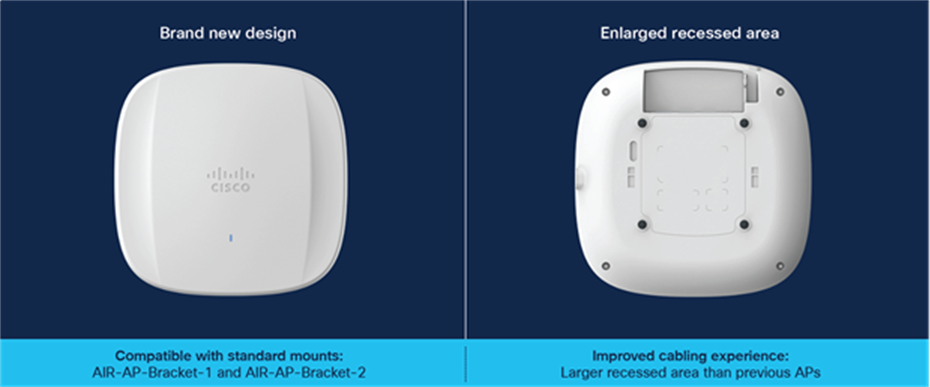
Front and back view of the Cisco Catalyst 9136I
This enlarged recessed area allows cables to be inserted into the ports without bending for an improved cabling experience. This is depicted in the figure below, compared with a Catalyst 9130 AP.
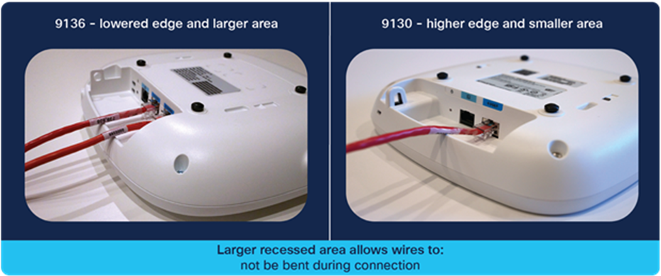
Comparing the cabling experience of the Catalyst 9136I vs. the Catalyst 9130AXI
The Catalyst 9136I has an incredible ratio of dimensions/weight to performance. It’s similar in size and weight to the midrange and high-end Catalyst Wi-Fi 6 APs and smaller and lighter than many of the Cisco Aironet® APs. However, it boasts a much more robust hexa-radio architecture, has two Multigigabit ports (compared to others that have one), and supports the entirety of Wi-Fi 6E.
Refer to the figure below for the dimensions and weight.
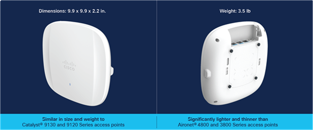
Dimensions and weight of the Catalyst 9136I AP
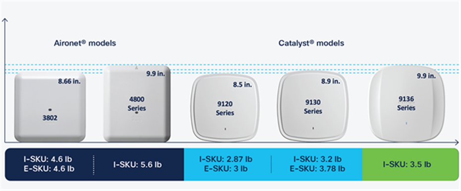
Comparing the Catalyst 9136I with previous generations of APs
The following figure depicts the ports and reset button on the Catalyst 9136I.
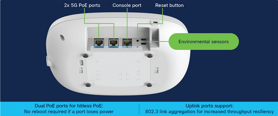
Physical ports and buttons of the Catalyst 9136I
Dual Multigigabit ports capable of up to 5 Gbps
The Catalyst 9136I comes with two 5-Gbps uplink ports, which can be used together to support a link aggregation configuration and provide uplink high availability and port PoE redundancy.
Port PoE redundancy: This feature allows you to plug a PoE source into both uplink ports for high availability and prevent the AP from restarting if power from a single source is lost. When both ports are plugged in, the AP will assume port 0 (left port) as primary and port 1 (middle port) as secondary. The AP will negotiate power in both the ports, but will draw power only from the primary source in Non-LAG deployment; however, if the primary source goes down, the secondary source will immediately become the primary.
Note:
1. As long as the power level provided on both ports is the same, the AP will continue to operate without disruption.
2. In LAG deployment, APs draw power on both the ports.
3. Use port 0 when only one link to the switch (single uplink) is needed. Use port 1 only in LAG mode.
To view the PoE input power of the Catalyst 9136I, on the Catalyst 9800 UI, navigate to Configuration > Wireless > Access Points > [select the Catalyst 9136I AP] > Interface > Power Over Ethernet Settings.
The Power Type/Mode value tells you the power input type of the primary port. You will be able to view the PoE type of the secondary port only if the PoE switchover occurs.
Table 5. Viewing the input power on the Catalyst 9136I
| Power over ethernet settings |
|
| PoE Type/Mode |
PoE/Full Power |
| PoE Pre-Standard Switch |
Disabled |
| PoE Power Injector MAC Address |
Disabled |
Link aggregation (LAG): This feature allows uplink redundancy by allowing both Multigigabit ports to load balance and take advantage of the higher speeds afforded by the combination.
Note:
1. The default mode of operation is non-LAG.
2. The maximum aggregated throughput is 5 Gbps, so even if the speed from both ports totals more than 5 Gbps, the performance will not be higher than 5 Gbps.
3. Use port 0 when only one link to the switch (single uplink) is needed. Use port 1 only in LAG mode.
To view the status of the AP’s ports on the Catalyst 9800 UI, navigate to Configuration > Wireless > Access Points > [select the Catalyst 9136I AP] > Interfaces > Ethernet Interfaces. This table allows you to view the port speeds connected to the AP for both GigabitEthernet0 and GigabitEthernet1.
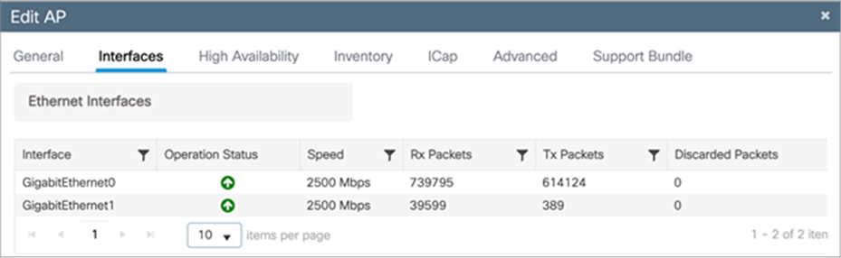
Viewing Catalyst 9136I port status and speeds; here both are connected to a 2.5-Gbps port.
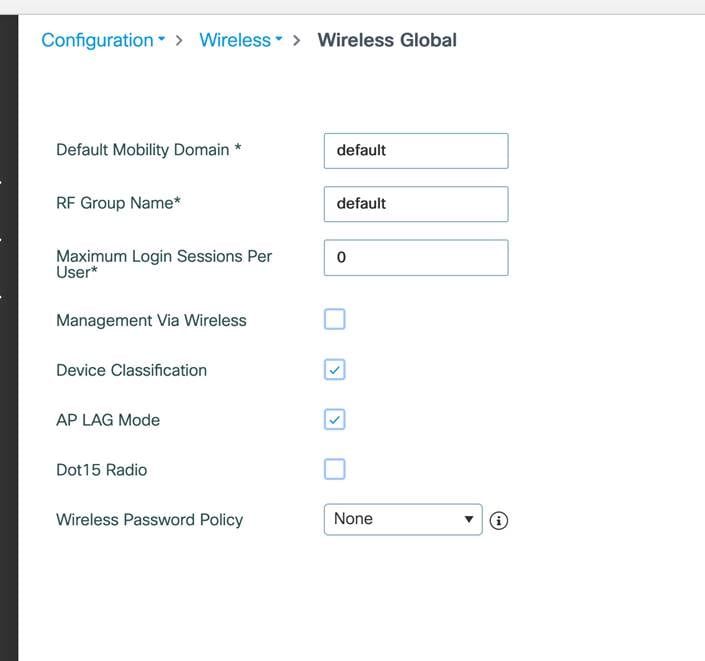
To have AP LAG support, the feature needs to be enabled on both the Catalyst 9800 controller for the AP and on the individual switches.
LAG can be configured at Global Level from Configuration à Wireless à Wireless Global
To configure LAG for AP join profile, navigate to Configuration > Tags and Profiles > AP Join > [Select AP Join Profile that Catalyst 9136I is associated with] > General > [select LAG Mode].
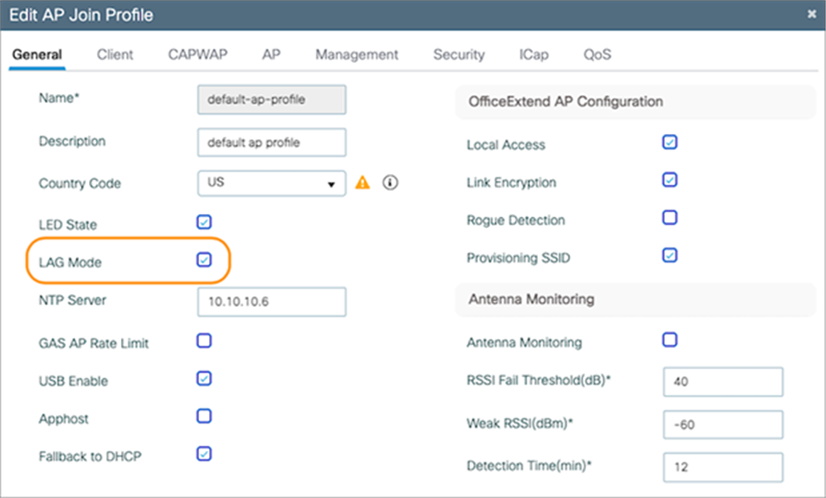
Enabling link aggregation on an AP join profile
Note: By default, LAG mode is disabled on an AP join profile.
AP LAG verification: To verify that link aggregation is now enabled, navigate to Configuration > Wireless > Access Points > [select the Catalyst 9136I AP] > Interfaces > Link Aggregation (LAG). Both AP LAG Configuration and AP LAG Operational Status should read Enabled.
Table 6. Verifying that AP LAG has been properly enabled
| Link Aggregation (LAG) |
|
| LAG Support for AP |
Yes |
| AP LAG Configuration status |
Enabled |
| AP LAG Operational Status |
Enabled |
Switch LAG verification: To complete the LAG configuration, it now needs to be configured on the switch. For this, two options exist: static LAG configuration and Link Aggregation Control Protocol (LACP).
Note: Catalyst 9136I does not support PAgP.
Refer to the “Configuring Layer 2 EtherChannels” and later sections of the Layer 2 Configuration Guide for examples on how to configure the switch for static LAG configuration and LACP. https://www.cisco.com/c/en/us/td/docs/switches/lan/catalyst9300/software/release/17-7/configuration_guide/lyr2/b_177_lyr2_9300_cg/configuring_etherchannels.html
Note: LAG can be configured only between two ports of the same speed. Differing speeds will not work, and the AP will default to the primary port (port0).
Dual Ethernet Deployment recommendations & limitations:
● Default mode of operation is Non-LAG. In Non-LAG deployment, the two ethernet ports can be connected to the same switch (single homed) or to two different switches (dual homed). In single homed deployment, it’s recommended to connect to the same switch or two different members of stack in a stack deployment or to two different line cards of a modular switch. The switch ports in single homed or dual homed have to be in the same VLAN. If the ports are configured to be different VLANs, then link redundancy will not work and will result in AP re-join with loss of traffic.
● In LAG mode, dual homed deployment is not supported. The Catalyst 9136I AP has to be connected to the same physical or logical switch.
● AP port authentication with 802.1X or MAB is currently not supported for link redundancy in both Non-LAG and LAG deployments. PoE redundancy will work with AP port authentication.
The following table summarizes the support and limitations:
Table 7. Dual Ethernet features supported and limitations
| Feature |
Non LAG |
Non LAG |
LAG |
LAG |
| PoE Redundancy |
Yes |
Yes |
Yes |
Yes |
| Link Redundancy |
Yes |
Yes |
Yes |
Yes |
| CAPWAP Control Connection to controller |
Yes |
Yes |
Yes |
Yes |
| Datapath – Local Mode |
Yes |
Yes |
Yes |
Yes |
| Datapath – Flex Mode |
Yes |
Yes |
Yes |
Yes |
| Datapath – Fabric Mode |
Yes* |
Not supported* |
Yes* |
Yes* |
| 802.1X Port Control |
Yes** |
Yes** |
No supported at the switch |
Not supported at the switch |
| MAB Authentication |
Yes** |
Yes** |
Not supported at the switch |
Not supported at the switch |
| IP connectivity (SSH, syslog) |
Yes |
Yes |
Yes |
Yes |
| Connectivity to Catalyst Center |
Yes |
Yes |
Yes |
Yes |
| Connectivity to Cisco Spaces |
Yes |
Yes |
Yes |
Yes |
Note: Not supported* - Current limitation in the software. Limitation will be removed in the future.
Yes** - Starting IOS XE 17.17.1 release.
Yes* - Starting IOS XE 17.15.1 release.
Console port
The console port (RJ-45) is used to access the AP’s command-line interface (CLI).
Reset button
The reset button is used to reset the AP to the factory settings.
Follow these steps to reset the AP.
Connect the console cable.
Unplug the PoE network cable from the switch.
Press and hold the Reset button.
Plug the power back into the AP.
Wait until the output on the console says “Button pressed. Configuration Reset is Activated.” Hold the button for 20 seconds for a full configuration reset and 30 seconds for a factory reset. Once the button is released, the AP will reboot to the state listed above.
Environmental sensors
The Catalyst 9136I has three built-in environmental sensors: air quality, humidity, and temperature. As shown in Figure 8, the openings on the right are where these sensors are located on the AP.
Note: More details on these sensors will be provided in the Internet of Things Integration section of this deployment guide.
The use of proper cable types will directly affect the performance of the Catalyst 9136I. Since this AP has 5-Gbps ports, the recommendation is to use either CAT6 or CAT 6a cable, which supports speeds of up to 10 Gbps. CAT 5e cables can still be used; however, there may be an effect on the AP’s performance.
Refer to the table below to compare cable types that can be used with the Catalyst 9136I.
Table 8. Cable types supported
| Cable type |
Speeds |
Maximum length |
| CAT 5e |
5 Gigabit |
328 feet (100 meters) |
| CAT 6 |
1/2.5/5 Gigabit |
330 feet (100 meters) |
| 10 Gigabit |
164 feet (50 meters) |
|
| CAT 6a |
10 Gigabit |
330 feet (100 meters) |
Regarding mounting, the Catalyst 9136I is compatible with the AIR-AP-Bracket-1 (default option) and AIR-AP-Bracket-2 brackets, and with the AIR-AP-T-RAIL-R and AIR-AP-T-RAIL-F for T-rail drop ceiling. These brackets are the same AP brackets provided for all Tier 2 and 3 enterprise-class APs for the last 15 years. This backward compatibility streamlines the day-0 process for brownfield deployments, allowing the Catalyst 9136I AP to be mounted on the existing bracket.
For more details on mounting the access point, refer to the following:
● Catalyst 9136I Getting Started Guide
● Access Point Mounting Instructions
The following figures provide details about the AIR-AP-Bracket-1 and AIR-AP-Bracket-2 for reference.
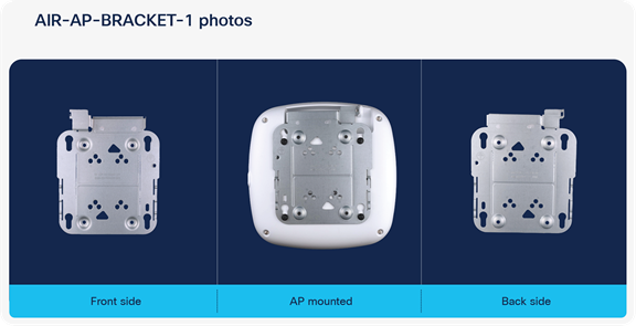
AIR-AP-BRACKET-1
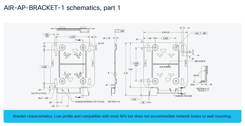
AIR-AP-BRACKET-1 schematics
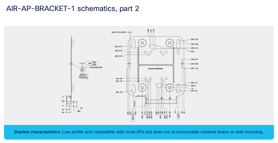
AIR-AP-BRACKET-1 schematics continued
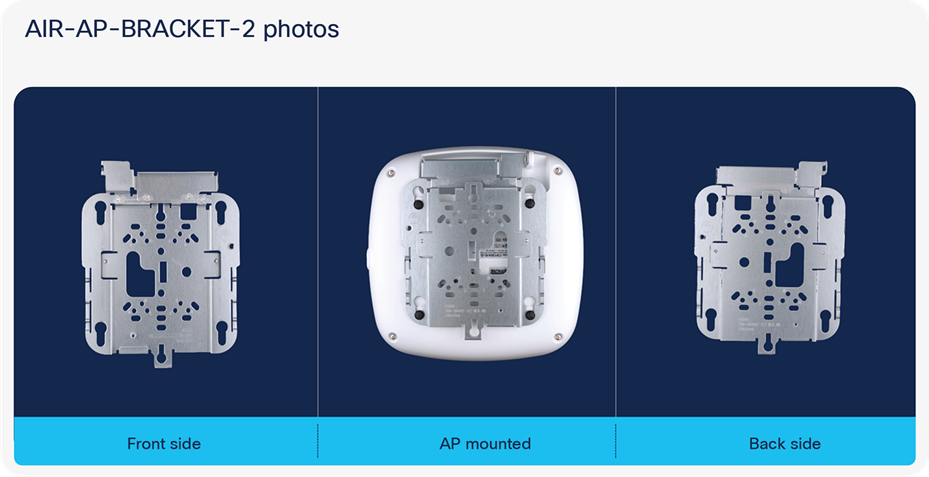
AIR-AP-BRACKET-2
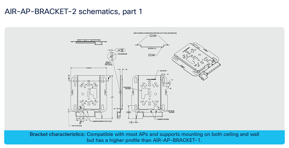
AIR-AP-BRACKET-2 schematics
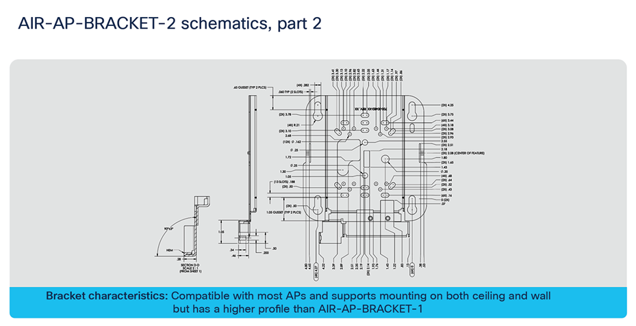
AIR-AP-BRACKET-2 schematics continued
The following table depicts the radio, port, USB performance, and maximum power draw based on the AP’s input power. For optimal performance, 803.2bt is required.
Table 9. PoE specifications for the Catalyst 9136I on Release 17.7.1
| Input power |
Number of spatial streams |
2.4-GHz radio (Slot 0) |
Primary |
Secondary |
6-GHz radio (Slot 3) |
mGig |
mGig |
USB |
AI/ML-driven scanning radio |
IoT radio |
Environmental sensors |
Max power draw |
| 802.3bt (Cisco UPOE®) |
16 |
4x4 |
8x8 or dual 4x4 |
4x4 |
5 Gbps |
5 Gbps |
Yes/9W |
Yes |
Yes |
Yes |
47.3W |
|
| 802.3at (PoE+) |
8 |
2x2 |
2x2 |
Disabled |
4x4 |
2.5 Gbps |
Disabled |
Disabled |
Yes |
Yes |
Yes |
24.4W |
| 802.3af (PoE) |
0 |
Disabled |
Disabled |
Disabled |
1 Gbps |
Disabled |
Disabled |
Yes |
Yes |
Yes |
14W |
|
Table 10. PoE specifications for the Catalyst 9136I on Release 17.8.1
| Input power |
Number of spatial streams |
2.4-GHz radio (Slot 0) |
Primary |
Secondary |
6-GHz radio (Slot 3) |
mGig |
mGig |
USB |
AI/ML-driven scanning radio |
IoT radio |
Environmental sensors |
Max power draw |
| 802.3bt (Cisco UPOE) |
16 |
4x4 |
8x8 or dual 4x4 |
4x4 |
5 Gbps |
5 Gbps |
Yes/9W |
Yes |
Yes |
Ye |
47.3W |
|
| 802.3at (PoE+) |
8 |
2x2 |
4x4 |
Disabled |
2x2 |
2.5 Gbps |
Disabled |
Disabled |
Yes |
Yes |
Yes |
24.4W |
| 802.3af (PoE) |
0 |
Disabled |
Disabled |
Disabled |
1 Gbps |
Disabled |
Disabled |
Yes |
Yes |
Yes |
14W |
|
In Release 17.7.1 the default 5-GHz spatial stream configuration for 802.3at is 2x2, whereas at 6 GHz it is 4x4. This default configuration is swapped in Release 17.8.1.
Note:
Slot 2 can operate only together with Slot 1 in 8x8 mode. Independent Slot 2 operation will be supported in a future software release.
AIR-PWRINJ7 is the 9136I’s official 802.3bt power injector.
802.3af is only for day-0 Control and Provisioning of Wireless Access Points (CAPWAP) connectivity between the AP and the Catalyst 9800 controllers.
Roadmap: In a future release, static and flexible PoE profiles will become available. These features will allow you to reduce the number of spatial streams or shut off radios entirely to reduce the maximum power draw or reallocate the power to other radios (if anything below 802.3bt is used).
Wi-Fi 6E takes the 802.11ax protocol to the next level by introducing a brand new spectrum, 6 GHz. This new spectrum is much wider than the legacy bands (2.4 GHz and 5 GHz) and allows wireless devices to take advantage of the performance enhancements introduced with Wi-Fi 6. The new spectrum is reserved for greenfield Wi-Fi 6 client operation only. This means that no previous generations of Wi-Fi will be permitted to operate there. This eliminates the performance-robbing requirements of backward compatibility often experienced in previous spectrums. In addition, the amount of spectrum provided encourages and enables the use of wider 80- and 160-MHz channels, which dramatically increases the speed while simultaneously providing enough room to operate without the co-channel interference issues experienced in the 2.4- and 5-GHz spectrums.
Wi-Fi 6E migration and deployment tips
Wi-Fi 6E (6 GHz) is a new spectrum standard, and with it comes several new requirements that were not there in the past. This section will go over key points about Wi-Fi 6E that play a part in the deployment of your Catalyst 9136I AP.
The figure below depicts a high-level representation of Cisco’s recommendations, tips, and tricks for deploying the Catalyst 9136I, while the sections that follow expand upon the details of each.
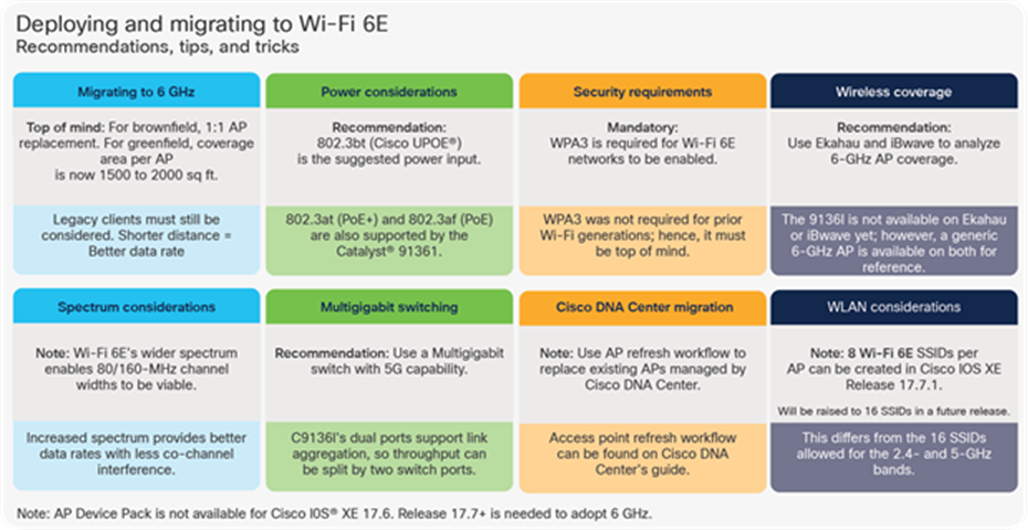
Wi-Fi 6E deployment and migration recommendations
Migration to 6 GHz
When deploying a new Wi-Fi 6E AP, there are two categories of considerations: whether you have a greenfield (no existing APs) or a brownfield (have existing APs) deployment.
Brownfield deployment: While we always recommend that you conduct site surveying and wireless coverage planning with tools such as Ekahau or iBwave, the general rule of thumb for a brownfield deployment is to have a one-to-one AP replacement. The reason is that you will likely still have to serve legacy band clients such as 2.4 or 5 GHz. If the legacy APs were strategically placed at the current location for the best legacy band coverage, the Catalyst 9136I will likely provide the best coverage there.
Greenfield deployment: If there are no existing APs, the suggestion is to use Ekahau or iBwave to conduct proper wireless planning before deploying any APs physically to ensure the best wireless coverage. Another rule of thumb is that each AP can cover an area of around 1500 to 2000 square feet (139.35 to 185.8 square meters). The figure below provides a visualization of the predicted coverage provided by the Catalyst 9136I and can be used as a general reference.
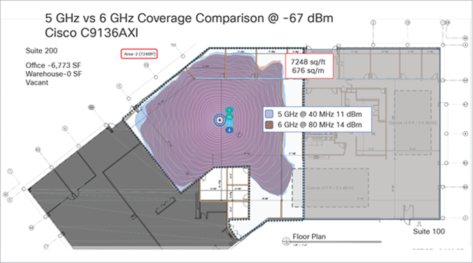
Catalyst 9136I RF propagation on 5 GHz and 6 GHz as represented on Ekahau
Power considerations
The Catalyst 9136I supports three power types: 802.3bt (Cisco UPOE, equivalent to 60W), 802.3at (PoE+, equivalent to 30W), and 802.3af (PoE, equivalent to 15W). The AP can be powered by any of these power types; however, to get the highest performance from the spatial streams, port speed, and USB power outage, an input power of 802.3bt must be used. Refer to the Power over Ethernet section above for a detailed overview of what input power type supports what radio, port, and USB settings.
When it comes to selecting a proper switching infrastructure to connect and power your wireless infrastructure, there are several factors to consider. To ensure that you have the most optimal switching infrastructure deployed, refer to the following Cisco UPOE+ white paper: https://www.cisco.com/c/en/us/solutions/collateral/enterprise-networks/nb-06-upoe-plus-it-ot-wp-cte-en.html.
Multigigabit switching
The Catalyst 9136I has two 5-Gbps ports, so to take advantage of its performance, your switches need to support Multigigabit speeds. As described in the Physical Port sections above, the Catalyst 9136I supports link aggregation, which allows you to combine the throughput speeds of two separate switch ports to get a combined speed of 5 Gbps. The recommendation is to have switch ports with speeds of at least 2.5 Gbps.
To learn more about Cisco Multigigabit switching technology, refer to the following webpage: https://www.cisco.com/c/en/us/solutions/enterprise-networks/catalyst-multigigabit-switching/index.html#~benefits
6-GHz spectrum considerations
With the introduction of Wi-Fi 6E, the spectrum has been significantly expanded compared with 5 GHz and especially 2.4 GHz. Spanning from 5925 MHz to 7125 MHz, we now have 59x 20-MHz channels, 29x 40-MHz channels, 14x 80-MHz channels, and 7x 160-MHz channels.
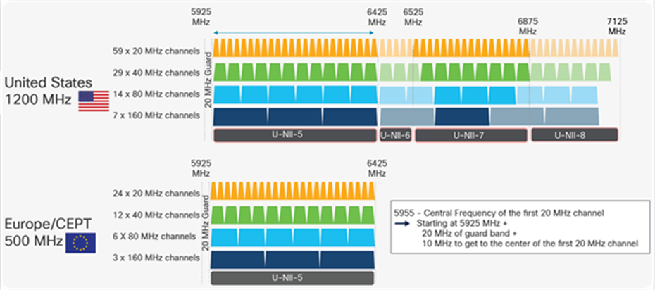
6-GHz spectrum in the United States and Europe
Note: Certain countries have yet to allow parts of or the entire 6-GHz spectrum. As of the time of writing this document, Europe/CEPT has approved only 5925 MHz to 6425 MHz, compared to the U.S., which has approved the whole spectrum.
The increase in spectrum width provides several advantages, with one of the most prominent being a lowered risk of co-channel interference. Since there are more channels to select from, it’s much less likely that APs in a similar physical location will be broadcasting RF on the same channels. In the past, this concern for co-channel interference is what prevented users from taking advantage of 80-MHz or 160-MHz bonded channel widths. Although throughput tests showed that they could provide great performance numbers, the problem was that deploying them in such a fashion was simply not practical in most production enterprise settings, because fewer channels meant a greater chance of interference and reduced overall capacity. With the introduction of Wi-Fi 6E, 80 and 160 MHz can now be used, allowing us to take advantage of the increased speeds in a production scenario.
To configure your Catalyst 9136I’s 6-GHz radio as 80 or 160 MHz, navigate to the following in your Catalyst 9800 controller: Configuration > Wireless > Access Points > [Select a 6 GHz radio] > Configure > Channel Width > [select 80 MHz or 160 MHz] > [Click Update & Apply to Device].
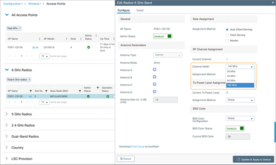
Configuring a 6-GHz radio on the Catalyst 9136I with a channel width of 80 or 160 MHz
Note: The instruction above demonstrates how to change the channel width manually as a reference. However, we recommend using the Catalyst 9800’s Radio Resource Management (RRM) feature with dynamic channel and bandwidth selection to automatically determine the channel and bandwidth the radios should be serving on for best performance. Refer to the 6 GHz Radio Resource Management section below for more details.
Another benefit of the 6 GHz spectrum is that it is still clean and without much interference compared with legacy bands such as 2.4 GHz, which shared the spectrum with the likes of Bluetooth Low Energy (BLE), Zigbee, microwave, and various other RF devices. With 6 GHz, we can expect that a majority of the spectrum use will be by other Wi-Fi 6E wireless clients of similar speeds, resulting in not only a more efficient spectrum but also a more secure one, thanks to the WPA3 mandate described in the Security Requirements section below.
Security requirements
Wi-Fi 6E requires that all WLANs be configured with WPA3 and Opportunistic Wireless Encryption (OWE), together with Protected Management Frames (PMF) enabled in both the AP and the client. Because previous bands didn’t require WPA3, this requirement allows Wi-Fi 6E to be the most secure spectrum. From a deployment perspective, this will likely affect how you create WLANs, since many legacy clients might not support WPA3 security. This is covered in the WLAN design section.
Note: The requirement to configure a Wi-Fi 6E WLAN with WPA3 security is not specific to Cisco but general to Wi-Fi 6E and applies to all vendors.
To learn more about WPA3, refer to the WPA3 Deployment Guide: https://www.cisco.com/c/en/us/products/collateral/wireless/catalyst-9100ax-access-points/wpa3-dep-guide-og.html
Wireless coverage planning
6 GHz is a new spectrum and therefore requires special planning and site surveying to determine the best areas for AP placement, especially in greenfield deployments. While 6 GHz provides faster speeds, its wavelengths are shorter, meaning that its range is shorter as well compared to 5 and 2.4 GHz. This factor may result in the Catalyst 9136I being placed in slightly different locations than previous APs that broadcast only 2.4 and 5 GHz to ensure optimal RF coverage when referring to a greenfield deployment.
Cisco recommends always conducting a site survey and using Ekahau or iBwave for wireless planning. These tools will allow you to upload floor plans of your building and simulate the RF of a Catalyst 9136I to determine where the APs should be placed for the best coverage. Once you’ve determined the optimal locations for your Catalyst 9136Is, you can deploy them physically.
Disclaimer: At the time of writing this document (March 2022), neither Ekahau nor iBwave supports the Catalyst 9136I in the production version of their software, but support will become available soon.
Cisco Catalyst Center AP refresh workflow
When migrating to new APs in a brownfield deployment, the new APs often take the place of incumbent APs with a one-to-one replacement. Assuming that your wireless infrastructure is being managed by Cisco Catalyst Center, you would also need to replace the APs managed by both the inventory and assigned to a floor map. To do this efficiently, Cisco Catalyst Center has an AP refresh workflow that allows you to easily replace old access points with new ones. This eliminates the tedious manual process of deleting old APs and streamlines the entire workflow.
Refer to the Build and Deploy Workflows chapter of the Cisco Catalyst Center User Guide for reference on the AP refresh workflow: https://www.cisco.com/c/en/us/td/docs/cloud-systems-management/network-automation-and-management/dna-center/2-1-1/user_guide/b_cisco_dna_center_ug_2_1_1/m_dnac_workflows.html
WLAN Design considerations
As stated in the security section, for an SSID to be broadcasted on 6GHz you need:
● WPA3 or OWE as L2 security
● Protected Management Frame (PMF) required
● Any other L2 security method is not allowed – no mixed mode is possible
From one side this is good because it makes 6GHz extremely secure, but it also means that you need to reconsider your SSID/WLAN design as multiple legacy clients you have in your network might not support these requirements and most likely your current WLAN configuration would prevent it from being supported on 6GHz.
So how would you design your SSID and how you define your security settings to adopt 6GHz but at the same time guarantee backward compatibility for existing clients?
The recommended option would be to add a separate WPA3 SSID, with a different SSID name, and broadcast it in all bands. The WPA3 capable clients in 2.4 GHz, 5 GHz and 6GHz bands would be able to connect and enjoy the most secure wireless network possible. Since you are not touching your existing SSIDs, legacy clients not supporting WPA3 will continue to connect to legacy SSIDs. The drawback of this option is that you need to broadcast an additional SSID, and you need to manage an additional wireless profile on the new WPA3 capable clients.
If the customer has a requirement to keep the SSID name the same, another possible option would be to create an additional WLAN profile with the same SSID name and different profile name and configure the security settings with WPA3 and PMF required and broadcast it only on 6GHz band. The existing SSID in 2.4 and 5 GHz will not be touched so clients not supporting 6GHz will continue to connect. As of today, multiple client vendors would not allow the client to be configured with two separate wireless profiles with different security settings but the same SSID name. This results in a drawback for this option: 6 GHz capable clients might not have the possibility to have an additional profile configured to connect to 2.4/5 GHz, and they must stick to 6GHz. This means that the 6GHz coverage must be correctly designed and must be the same as 2.4 and 5Ghz, as you cannot rely on clients falling back to another band. An additional note: seamless roaming across different WLANs (even with same SSID) is not supported, the client will have to go through a full reconnection.
More details on WLAN creation can be found in the Creating a Wi-Fi 6E WLAN section below.
Note: In Release 17.7.1, you are limited to eight Wi-Fi 6E SSIDs. However, this limit will be increased to the standard 16 SSIDs in a future release This limitation affects only 6GHz and for legacy bands, you can configure up to 16 SSIDs.
The workflow for creating a 6-GHz WLAN is similar to that for all legacy bands with only a couple of differences, one being the security requirement of WPA3.
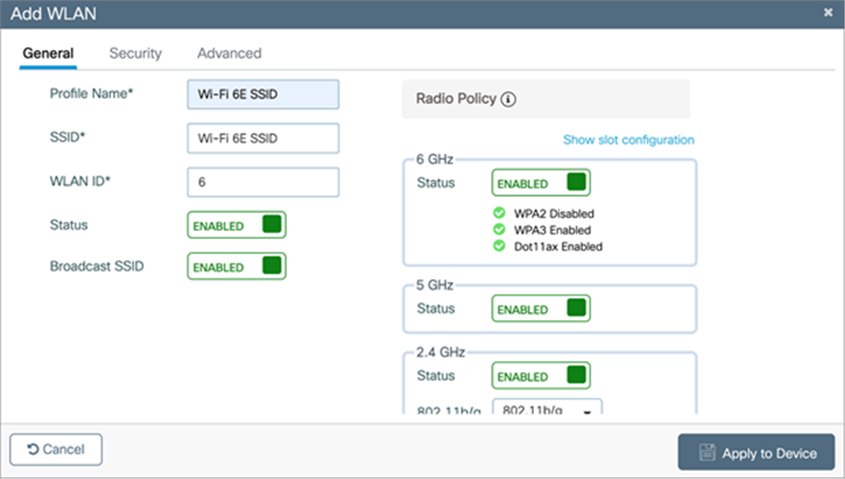
To create a 6-GHz WLAN, navigate to Configuration > Tags and Profiles > WLANs > [Click +Add]. Input a Profile Name (WLAN profile identifier) and SSID (Wi-Fi name being broadcasted), and then change the Status to Enabled.
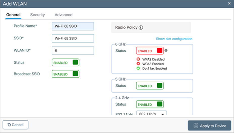
Inputting the WLAN’s Profile Name and setting the status to Enabled
Notice that although 6 GHz is enabled, it’s highlighted in red. This is because by default, the security of WLANs is set to WPA + WPA2, which doesn’t meet the requirement of 6 GHz. Notice that the text within the 6 GHz Status box highlights the requirements.
To change the security to WPA3, click the Security tab and then, from the drop-down menu located at Layer2 > Layer 2 Security Mode, select WPA3.
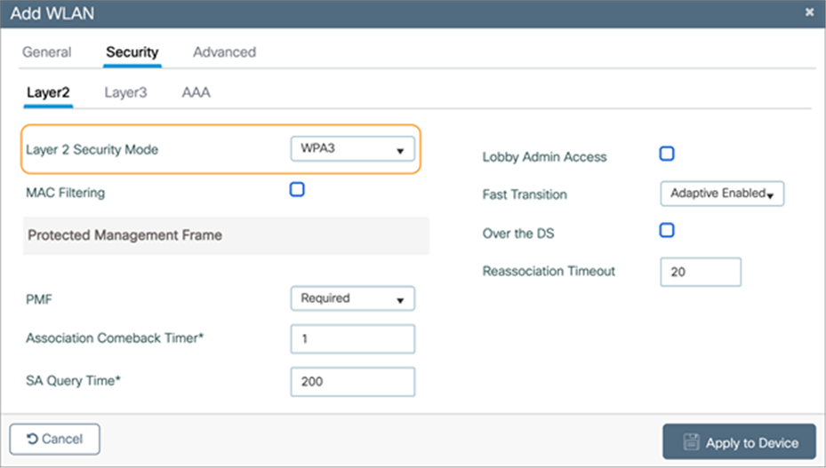
Changing a WLAN to WPA3 security
Scroll down to the bottom and select at least one Authentication Key Management (AKM) option: Secure Agile Exchange (SAE), OWE, Fast Transition (FT) + 802.1X, or 802.1X-SHA256.
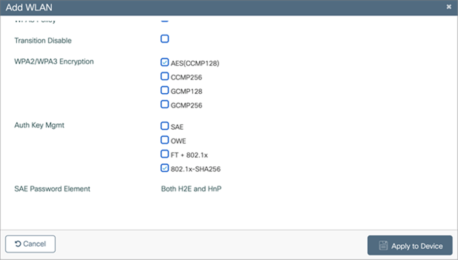
Selecting an AKM option for the WLAN
Navigate back to the General tab, and you’ll notice that the 6 GHz status is now enabled and green, meaning that all configurations are satisfactory. Click Apply to Device to complete the WLAN creation workflow.
6 GHz status during WLAN creation is now green
Option: If you want to verify that 802.11ax features such as downlink and uplink OFDMA, downlink and uplink MU-MIMO, and BSS Target Wake Up Time are enabled, click Advanced, and scroll to the bottom.
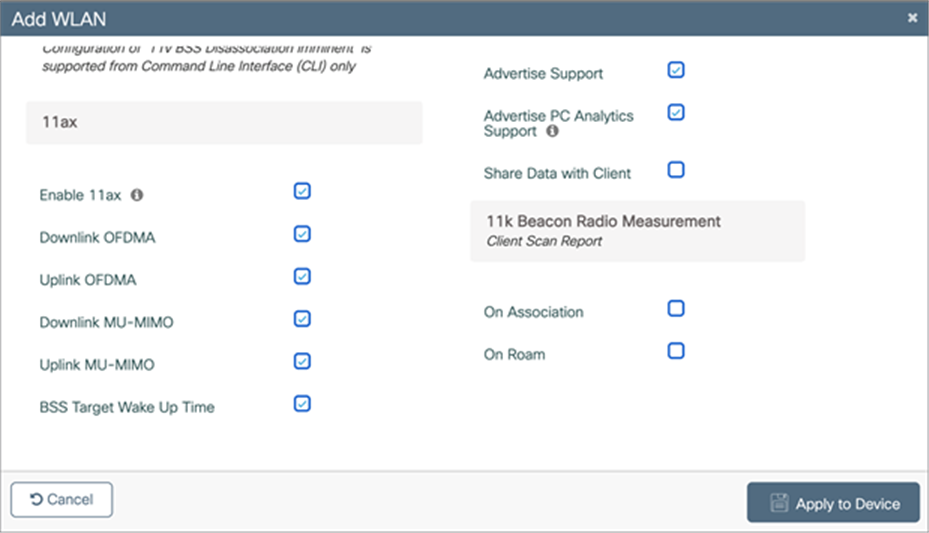
Verifying that 802.11ax features are enabled on the Wi-Fi 6E WLAN
AP discovery is how wireless clients discover APs with WLANs that they would like to join. The legacy method includes two options, passive scanning and active scanning.
Passive scanning: The AP will periodically broadcast beacon frames that the wireless client can detect, providing metadata for each WLAN the AP is broadcasting, such as the SSID name, data rates, etc.
Active scanning: The wireless client will send probe requests to nearby APs when it wants to join a WLAN. If an AP detects this probe request, it will send back a probe response with WLAN information such as the SSID name, data rates, etc.
In both cases, using the information received from the AP in either the beacon frame or probe response, the wireless client can request to join the AP’s WLAN.
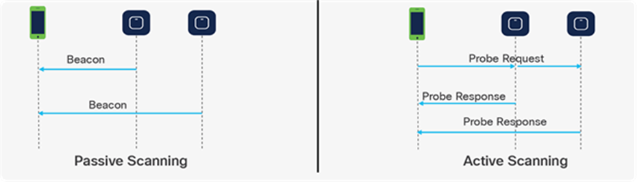
Legacy AP discovery mechanisms – passive vs. active scanning
These methods worked well with the previous 2.4- and 5-GHz bandwidth networks, since 2.4 GHz had only 3x 20-MHz channels and 5 GHz had 25x 20-MHz channels, as depicted in the figure below.
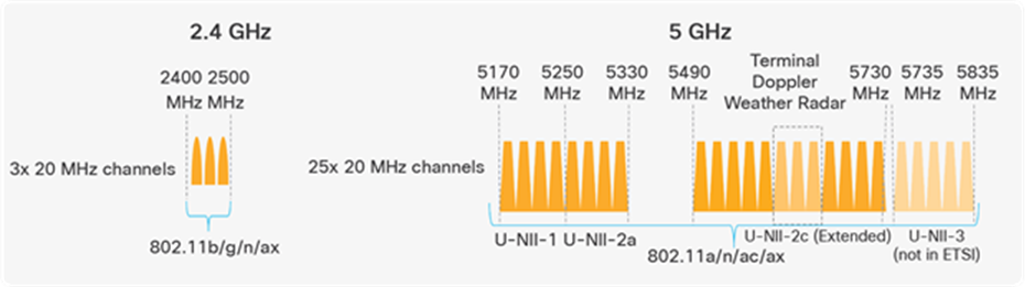
Depiction of the 2.4- and 5-GHz spectrum
However, with the introduction of 6 GHz, we now have 59x 20-MHz channels (depicted in the figure below), more than two times what we had in 5 GHz. Because wireless clients can send probe requests only on 20-MHz channels, this increases the passive scan time significantly to 6 seconds, which is far too much delay in the world of wireless.
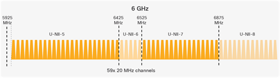
Depiction of the 6-GHz spectrum
Since legacy AP discovery mechanisms are not efficient when addressing the expanded spectrum of 6 GHz, new AP discovery mechanisms have been created. Of these new discovery mechanisms, there are two categories, out-of-band and in-band discovery, as shown in the figure below.
Out-of-band discovery mechanism: Used when 2.4-, 5-, and 6-GHz bands all exist in the RF environment.
In-band discovery mechanisms: Used when only the 6-GHz band exists in the RF environment.
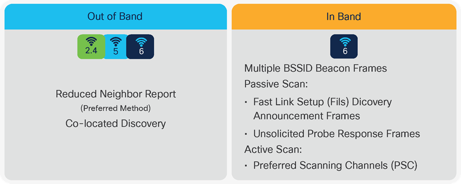
Out-of-band and in-band AP discovery mechanisms
Out-of-band AP discovery mechanism
For the out-of-band discovery mechanism, we have the Reduced Neighbor Report (RNR), as depicted in the figure below, which includes WLAN information for all 6-GHz-capable WLANs within the beacon and probe responses of the AP’s 2.4- and 5-GHz radios. Concatenating all 6-GHz WLAN data into these existing frames eliminates the need for additional packets to be sent, which conserves airtime and allows the network to steer the clients toward 6 GHz if they are capable.
Note: RNR is enabled by default as part of 6 GHz.
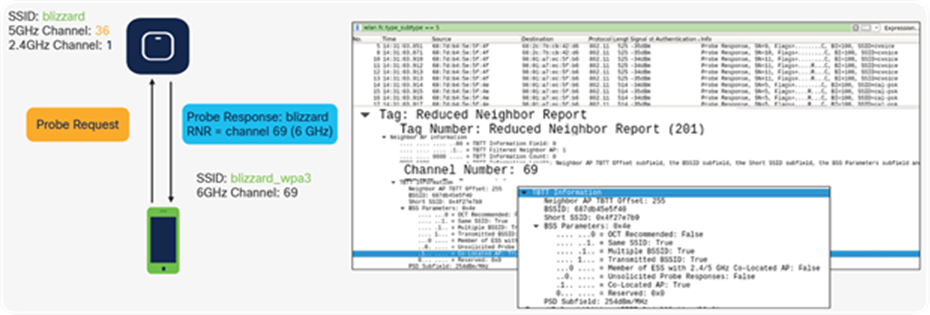
Visual representation of RNR and how it’s shown in Wireshark
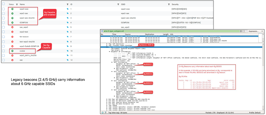
Multiple 6-GHz WLAN metadata in a single beacon frame as part of RNR
In-band AP discovery mechanisms
Fast Initial Link Setup
For the first in-band discovery mechanism, we have the Fast Initial Link Setup (FILS) frame, which is part of the 802.11ai standard. A problem that exists in wireless today is APs being overwhelmed by probe requests, and this is especially true in high-density environments. FILS directly addresses this and helps to make AP discovery in a 6-GHz band more efficient by reducing probe request overhead and prolonging a wireless client’s dwell time between beacon frames.
The following step-by-step explanation is based on the figure below.
APs broadcast beacon frames that contain detailed WLAN metadata every 100 milliseconds.
If a wireless client starts WLAN discovery right after a beacon is sent, it will continuously send probe requests until the next beacon is detected, taking up airtime.
FILS frames, which are smaller than beacon frames, are sent every 20 milliseconds between beacon frames and contain high-level WLAN information such as the short SSID name, channel, and Target Beacon Transmission Time (TBTT), but are sufficient to tell a wireless client whether the WLAN is something it wants to join.
If a client starts discovery right after a beacon frame is sent, within 20 milliseconds it will detect a FILS frame. If it decides that this is a WLAN it would like to join, it will go into sleep mode (stop sending probe requests) until the next beacon frame is detected.
When the next beacon frame is detected, the wireless client will use the WLAN’s detailed metadata from that frame to join the WLAN.
Ultimately, FILS frames help to reduce the number of probe requests being sent from clients and make the airtime more efficient.
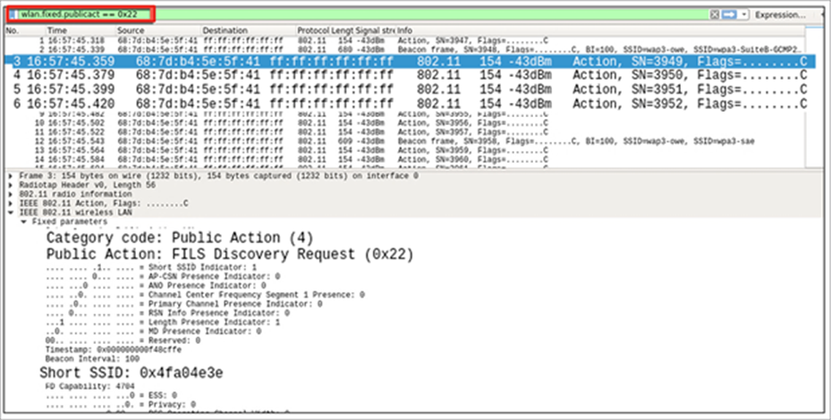
FILS discovery request frames shown in Wireshark
Unsolicited Broadcast Probe Response
The second in-band method is the Unsolicited Broadcast Probe Response (UBPR). When this feature is enabled and a client sends a probe request, the AP will send a probe response; however, rather than being sent to the client’s MAC address, the probe response is broadcasted, as the name suggests. Broadcasting the probe response enables other wireless clients to use this same probe response to join the WLAN, reducing probe request overhead. The UBPR frames are transmitted every 20 seconds, carry multiple BSSIDs, and contain all information needed for the association as any normal beacon frame.
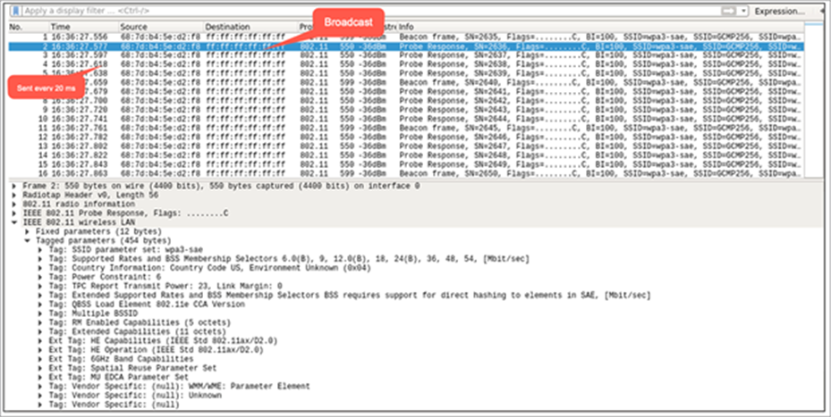
UBPR frames in Wireshark
Enabling FILS or UBPR
FILS and UBPR are equivalent greenfield, in band 6Ghz discovery mechanisms.
To enable FILS discovery or UBPR, on your Catalyst 9800 controller, navigate to Configuration > Tags & Profiles > RF/Radio > [Select RF profile] > 802.11ax.
Next to 6 GHz Discovery Frames, you have the option to enable either None, Broadcast Probe Response, or FILS Discovery. Default is None. If you select Broadcast Probe Response, you can also configure the response interval if desired.
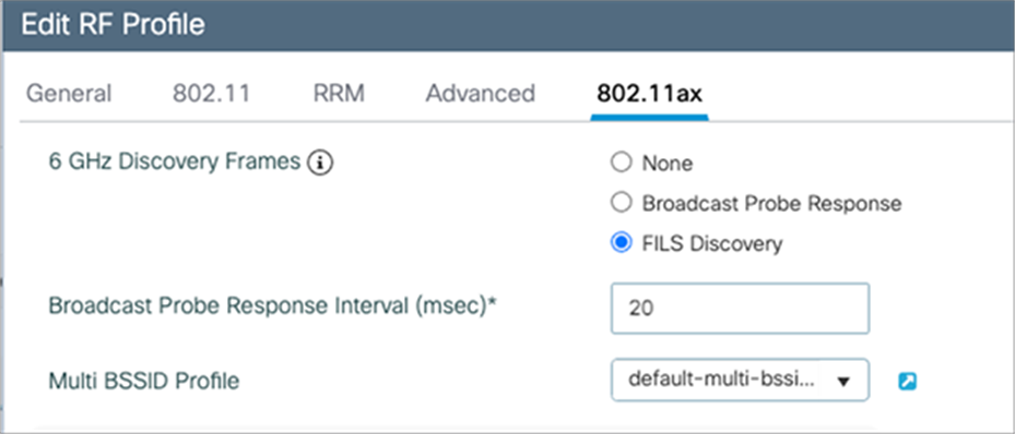
Configuring FILS discovery on the Catalyst 9800 controller.
Note: Only one of these 6-GHz discovery frames methods can be enabled at a time.
6-GHz Radio Resource Management
Radio Resource Management (RRM) is a collection of algorithms that allow the Catalyst 9800 controller to automatically manage your network through a few key features, including Dynamic Channel Assignment (DCA), Preferred Scanning Channels (PSC), Dynamic Bandwidth Selection (DBS), Transmit Power Control (TPC), and Flexible Radio Assignment (FRA). This section will walk you through a few notable changes to RRM with the introduction of 6 GHz.
Dynamic Channel Assignment
Dynamic Channel Assignment (DCA) is a feature that dynamically manages channel assignments, channel width, and many other factors for an RF profile. It evaluates the channels for each AP radio and will automatically adjust the assigned channels based on environmental factors such as co-channel interference, rogues, noise, channel load, and DCA sensitivity. By default, this feature is enabled on the Catalyst 9800 controller for your 6-GHz network, and the recommendation is to keep it enabled.
To verify that DCA is enabled for the RF group that the Catalyst 9136I is assigned to, navigate to Configuration > Tags and Profiles > RF/Radio > [Select an RF Profile] > RRM > DCA.
You can see a list of DCA channels in the figure below, many of which are specified to the 6-GHz band.
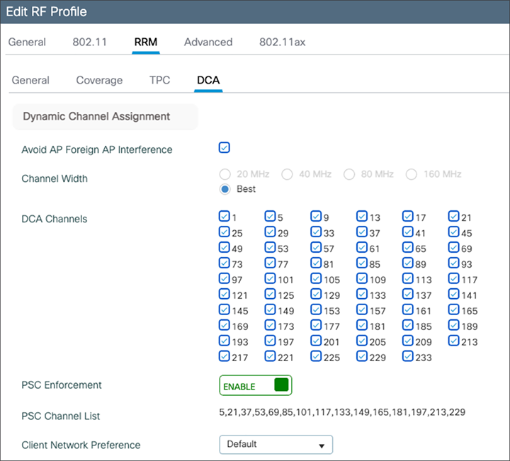
Verifying DCA configurations in the RF group
For more details on DCA, refer to the Radio Resource Management white paper: https://www.cisco.com/c/en/us/td/docs/wireless/controller/technotes/8-3/b_RRM_White_Paper/dca.html
Preferred Scanning Channels
Preferred Scanning Channels (PSC) is a feature categorized under DCA that designates every fourth 20-MHz channel for active probing by Wi-Fi 6E clients. It is used when channels are bonded in 80 MHz and restricts scanning down to 15 channels rather than 59, increasing the overall efficiency of RF scanning.
PSC enforcement is disabled by default and the recommendation is to enable it. The PSC list is provided in the Catalyst 9800 controller interface at Configuration > Tags & Profiles > RF/Radio > [Select an RF Profile] > RRM > DCA, as shown in the figure above. When enabled, only PSC channels will be offered as the primary channel with 80-MHz channel bandwidth. The recommendation is to enable PSC when using 80-MHz bonded channels for more efficient network scanning from both the wireless client and other APs in the network.
The figure below depicts how PSC works.
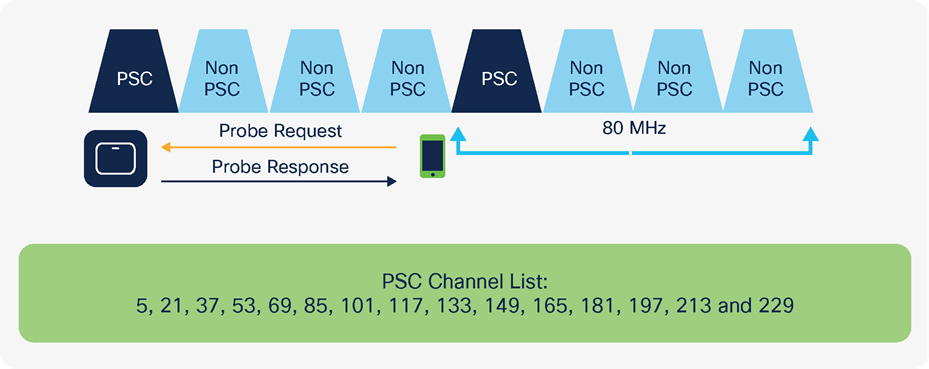
Visual representation of how PSC works
Dynamic Bandwidth Selection
Dynamic Bandwidth Selection (DBS) is a feature that is categorized under DCA. It automatically dictates the channel width of the network. For 6 GHz, it has a bias toward selecting 80-MHz channel bandwidth in countries with full 6-GHz spectrum (such as the U.S. and South Korea) and 40 MHz in countries with partial 6-GHz spectrum. The DBS starts at 80 MHz as the default bandwidth and will lower the bandwidth based on DCA metrics such as neighbor density, high interference, and noise floor, and if it detects that most clients are only 20 MHz.
DBS is enabled by default when the Channel Width is set to Best, as shown in the figure below, and will help ensure that the most optimal channel width is selected; no static assignment is possible. You can navigate to the window shown below on the Catalyst 9800 controller via Configuration > Tags and Profiles > RF/Radio > [Select an RF Profile] > RRM > DCA.
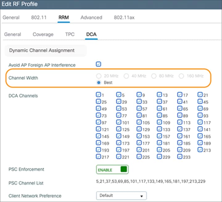
DBS option enabled by setting Channel Width to Best
Transmit Power Control
Transmit Power Control (TPC) automatically optimizes a radio’s transmit (Tx) power based on neighboring RF to maximize coverage while minimizing co-channel interference. The TPC algorithm is run after the convergence of DCA and DBS. When it comes to 6 GHz, it considers the Tx power increase due to the width and revised effective isotropic radiated power (EIRP) adjustments on the Neighbor Discovery Packet (NDP). The TPC algorithm also allows it to maintain a higher Tx power compared to the 2.4- and 5-GHz bands due to the lower chance of co-channel interference.
To view the configured TPC threshold, navigate to Configuration > Tags and Profiles > RF/Radio > [Select an RF Profile] > RRM > TPC.
The figure below depicts the default but configurable thresholds of TPC. The recommendation is to leave the values at their defaults.
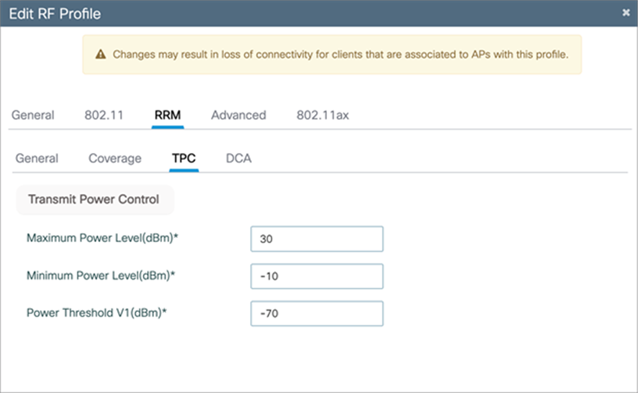
TPC thresholds
OFDMA is an 802.11ax feature that allows the AP to share the bandwidth resources and send out multiple packets in parallel, which both maximizes the efficiency of the channel width and mitigates any network contention. With Wi-Fi 6E, OFDMA works in the same way except that it has an increased spectrum to work with. By default, 6-GHz radio configurations are enabled; however, to verify this, navigate to Configuration > Radio Configuration > High Throughput.
The figure below depicts the different spatial stream and modulation and coding scheme (MCS) combinations, all enabled by default.
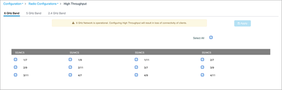
Verifying the spatial streams and MCS of the 6-GHz configuration on a Catalyst 9800 controller.
Configuring 6-GHz Client Steering
Since the 6-GHz bandwidth is new, most clients will automatically associate to the AP’s 2.4- and 5-GHz radios by default. 6 GHz Client Steering is a feature that will suggest that clients on the 2.4- and 5-GHz bands join the 6-GHz band when certain criteria are met.
Note: 6 GHz Client Steering is configurable at the WLAN level.
Navigate to Configuration > Tags and Profiles > WLANs > [Edit existing WLAN or add new WLAN] > Advanced, then check the box next to 6 GHz Client Steering.
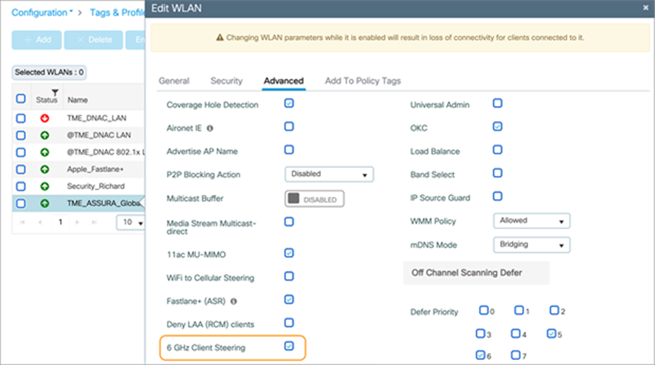
Enabling 6 GHz Client Steering
Navigate to Configuration > Wireless > Advanced > 6 GHz Client Steering, then configure the thresholds for 6-GHz Client Steering as you see fit.
Note: The recommendation is to leave these thresholds at their defaults.
The configurable thresholds in the figure below include:
● 6 GHz Transition Minimum Client Count
◦ The minimum number of clients that must be associated with the AP for 6 GHz Client Steering to be triggered.
● 6 GHz Transition Minimum Window Size
◦ The minimum difference in wireless client count between the 6-GHz band and 2.4- or 5-GHz band. The purpose of this threshold is to load-balance clients between different radios.
● 6 GHz Transition Maximum Utilization Difference (%)
◦ Indicates the maximum channel utilization difference at which 6 GHz Client Steering will be triggered.
● 6 GHz Transition Minimum 2.4 GHz RSSI Threshold (dBm)
◦ Indicates the minimum 2.4-GHz RSSI value at which 6 GHz Client Steering will be triggered.
● 6 GHz Transition Minimum 5 GHz RSSI Threshold (dBm)
◦ Indicates the minimum 5-GHz RSSI value at which 6 GHz Client Steering will be triggered.
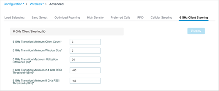
Configuring the thresholds for 6 GHz Client Steering
When deploying APs, one wireless design consideration is roaming, or how wireless clients can seamlessly move from one AP to another when they physically change locations. The main thing to keep in mind is the need to support clients that do not support WPA3 or Wi-Fi 6E. In such a scenario, clients that are currently on a 2.4- or 5-GHz band will not be able to roam to areas that contain only 6 GHz. Therefore, when designing your network, you may want to ensure that every access point is still broadcasting legacy bands with legacy security methods to ensure that there are no coverage holes for those wireless clients.
When a Wi-Fi 6E client associates with the Catalyst 9136I, you will be able to verify that it’s associated as a Wi-Fi 6E client by navigating to Monitoring > Wireless > Clients > [Select Wi-Fi 6E client] > 360 View.
In the figure below, the data next to Capabilities will read 802.11ax – 6 GHz if the wireless client is associated with the Wi-Fi 6E network.
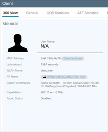
Wi-Fi 6E wireless client metadata
Cisco CleanAir Pro and the AI/ML-driven scanning radio
Wi-Fi 6E (6 GHz) was introduced with the Catalyst 9136I, and with it come new challenges for RF visibility and much more spectrum to monitor. In the past, the Catalyst 9100 APs relied on Cisco CleanAir (software) and the RF-ASIC (hardware) for features such as packet capture, spectrum analysis, interference detection, and rogue and wireless intrusion prevention system (WIPS) detection. CleanAir and the RF-ASIC were great for RF visibility for the 2.4- and 5-GHz bands; however, with 6 GHz, CleanAir Pro and the AI/ML-driven scanning radio are being introduced to increase the performance and granularity required to manage this new spectrum (all 1200 MHz of it).
CleanAir Pro is software designed specifically for 6 GHz and the all-new challenges that have come with the introduction of 1200 MHz of spectrum. While many of its features work in conjunction with the AI/ML-driven scanning radio, CleanAir Pro also works with the Catalyst 9136I’s serving radios as well. Unlike previous generations of APs, CleanAir Pro can even decode high-efficiency (HE, 802.11ax) frames, which is crucial since Wi-Fi 6E uses only HE frames. In the future, there will even be an ML-based interferer classification built directly into the AP software for more efficient interferer analysis, rather than loading the CONTROLLER or Cisco Catalyst Center.
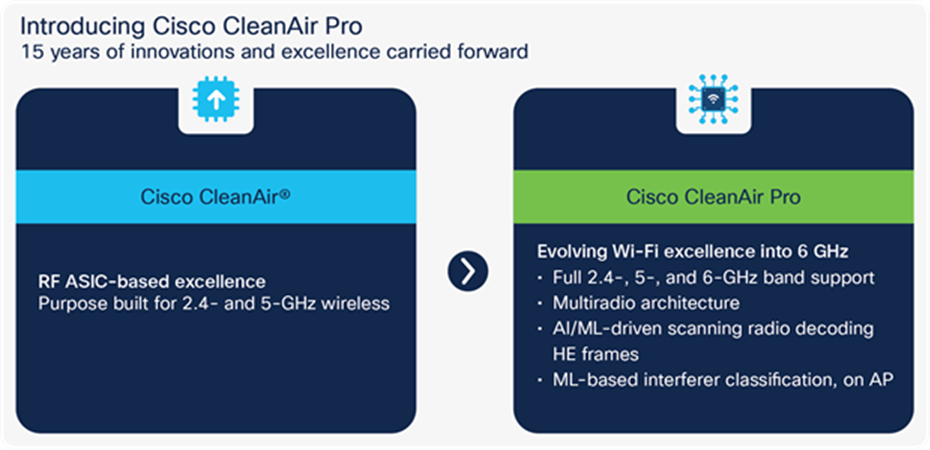
High-level comparison of CleanAir Pro and CleanAir
With the initial release of the Catalyst 9136I running Cisco IOS XE 17.7.1, features such as packet capture (with Intelligent Capture), rogue management, and adaptive WIPS (aWIPS) detection on 6 GHz are supported. These are supported with CleanAir Pro together with the AP’s serving radios but will use the AI/ML-driven scanning radio starting with Cisco IOS XE Release 17.8.1. Starting with Release 17.8.1, we will also be supporting spectrum analysis (with Intelligent Capture) to provide a detailed view of your entire 6-GHz spectrum. In future releases, many more RF visibility-related features will be added as part of CleanAir Pro to help take your RF visibility to the next level. More details on each feature will be included in this deployment guide as they become available.
Recommendation: The suggested release for the Catalyst 9136I is Cisco IOS XE 17.8.1, since CleanAir Pro will work together with the AI/ML-driven scanning radio beginning with this release.
Cisco Catalyst Center and Wi-Fi 6E
Cisco Catalyst Center is Cisco’s network monitoring software, for everything related to analytics. With the introduction of Wi-Fi 6E, Cisco Catalyst Center version 2.3.2 will support 6 GHz from all perspectives. This includes the Wi-Fi 6E dashboard, Intelligent Capture for packet capture and spectrum analysis on 6 GHz, rogue and aWIPS detection on 6 GHz, and many others.
The following are a few examples of some features on Cisco Catalyst Center related to Wi-Fi 6E.
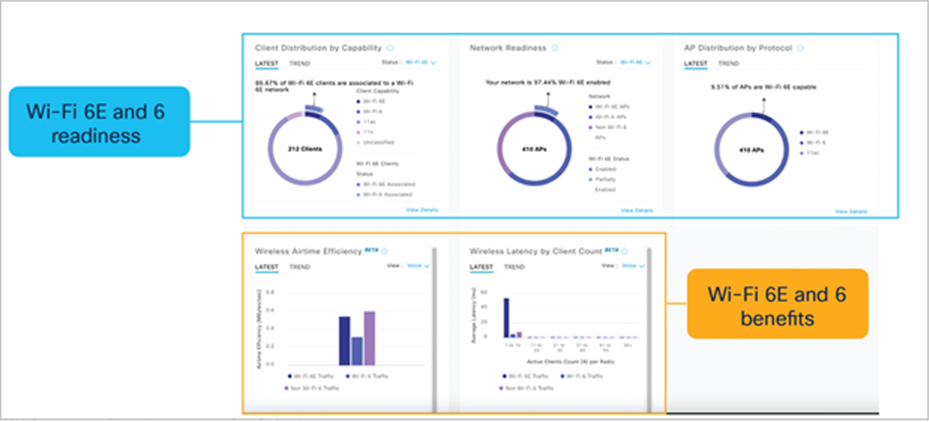
Wi-Fi 6/6E dashboard – View network readiness and benefits for Wi-Fi 6/6E
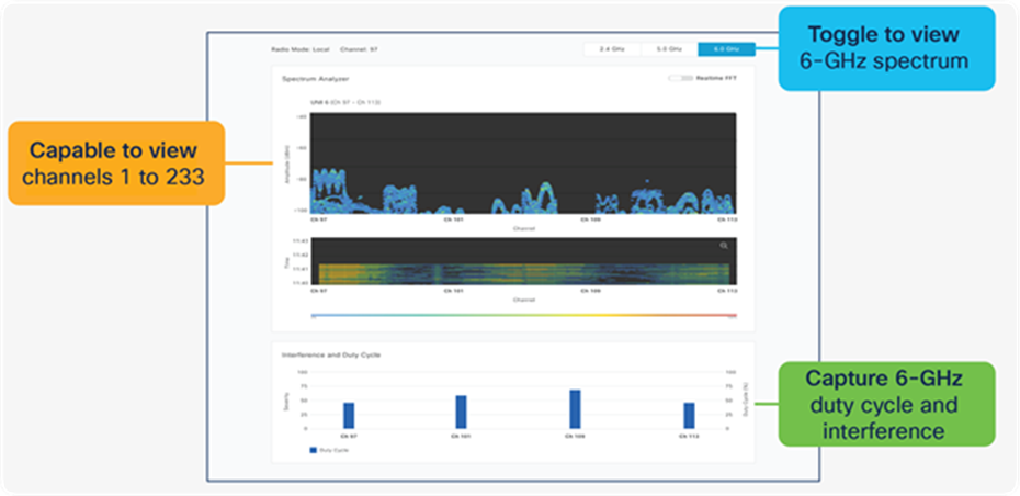
Spectrum analysis – Visualize RF spectrum energy, not only for 2.4 and 5 GHz, but now also for 6 GHz
Note: Spectrum analysis is part of the Intelligent Capture feature set.
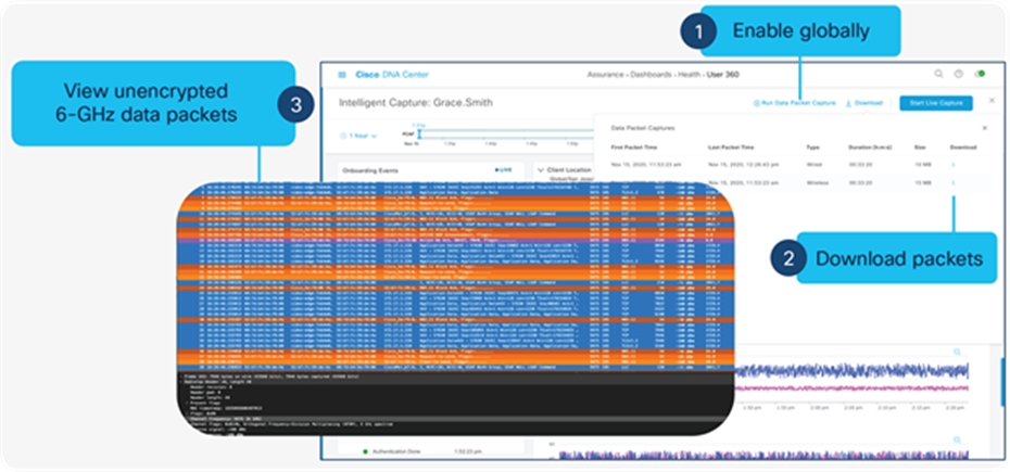
Data packet capture – Capture unencrypted data packets, not only for 2.4 and 5 GHz, but now also for 6 GHz
Note: Data packet capture is part of the Intelligent Capture feature set.
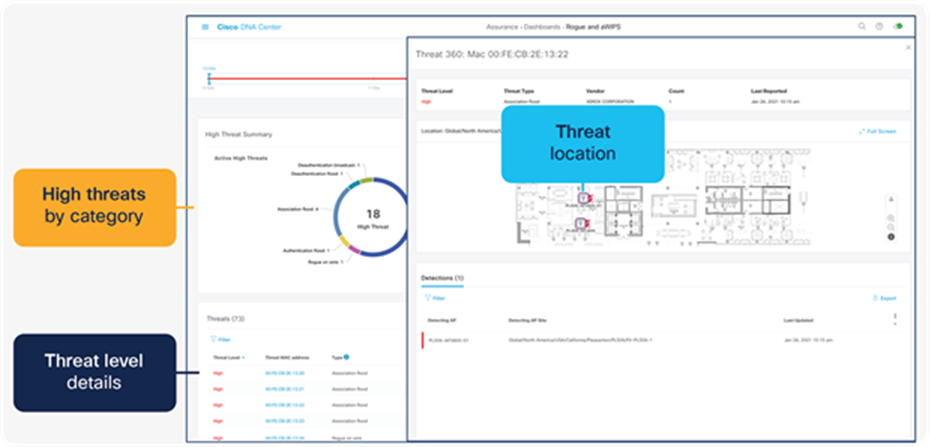
Rogue management and aWIPS – Detects wireless threats in the environment, not only for 2.4 and 5 GHz, but now also for 6 GHz
Note:
● Refer to the Software Solution Compatibility section in this deployment guide for the exact features released with Cisco IOS XE 17.7.1 and Cisco Catalyst Center 2.3.2.
● Please refer to the Cisco Catalyst Center user guide for a detailed overview.
Internet of Things integration
Environmental sensors with Cisco Spaces
The Catalyst 9136I has three built-in environmental sensors, air quality, humidity, and temperature, that will be integrated with Cisco Spaces’ rich map. This integration will provide an immersive experience for facility managers to help ensure a safe working environment, especially geared toward back-to-office safety use cases.
The figure below depicts a mockup of the rich map feature in Cisco Spaces and how the environmental sensor data would be used.
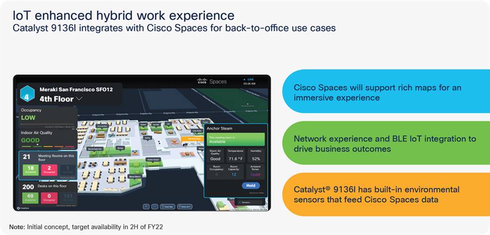
Integrating the Catalyst 9136I’s environmental sensors with Cisco Spaces’ rich map
Note: The figure above is an early-stage mockup and could differ from the final product.
The figure below depicts the details of the three environmental sensors built into the Catalyst 9136I.
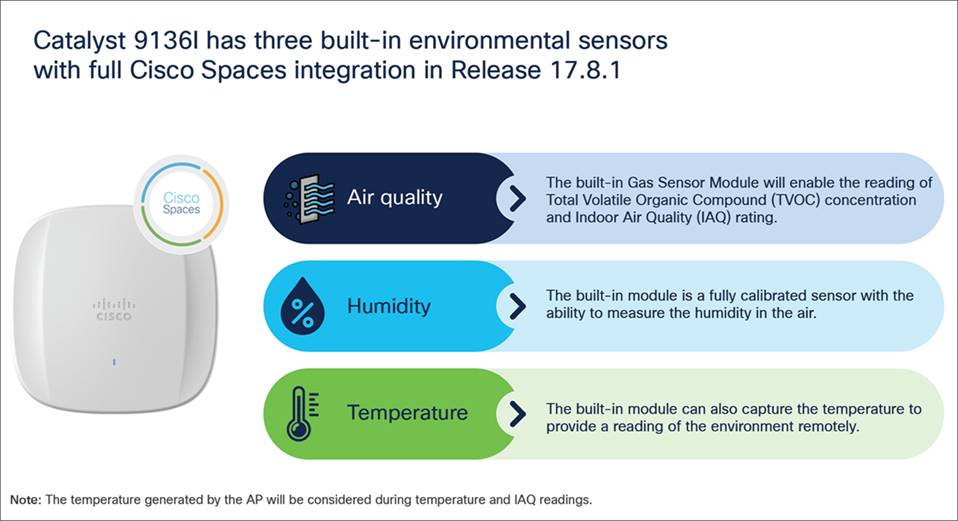
Environmental sensor overview of the Catalyst 9136I
Note:
● The support for environmental sensors is available starting Cisco IOS XE Release 17.8.1.
● The area where the sensors are located is separated from the rest of the AP’s internal circuitry.
The figure below depicts how environmental sensor data is sent from the Catalyst 9136I to Cisco Spaces.
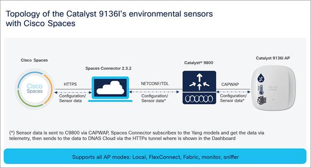
Topology of the Catalyst 9136I’s environmental sensors with Cisco Spaces
Enterprise wireless IoT with application hosting
The Catalyst 9136I allows users to load Cisco IOx applications onto the platform to solve IoT use cases by acting as an IoT gateway. These IOx applications can communicate with an RF-USB dongle connected to the USB port of the AP and talk to the surrounding IoT devices. IoT device data is then sent through the AP and to a back-end server. With the Catalyst 9136I, the USB port now outputs a total of 9 watts of power, which is double that of the previous Catalyst 9100 APs. This allows for a new array of IoT use cases that were previously limited due to power consumption.
Use cases for application hosting include retail management with electronic shelf labels, asset management with environmental sensors and real-time location, and medical management with tracking of patient vitals.
The figure below depicts the basic topology of application hosting with the Catalyst 9136I.
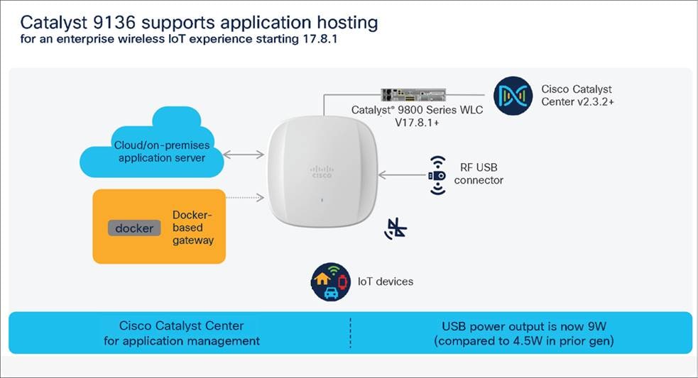
Application hosting topology with the Catalyst 9136I
The support for IoX framework support on C9136I is available starting Cisco IOS XE Release 17.8.1. For more information on application hosting, refer to the deployment guide: https://www.cisco.com/c/en/us/products/collateral/wireless/access-points/guide-c07-744305.html
The Cisco Catalyst 9136I supports a new mode called Site Survey. The purpose of this mode is to allow users to conduct wireless site survey testing using a single access point, including understanding RF propagation, client join metrics, and so on, without the need for a controller. This mode converts the AP into a limited standalone mode, enabling it to broadcast 2.4-, 5-, and 6-GHz SSIDs and allowing wireless clients to join via an internal Dynamic Host Configuration Protocol (DHCP) pool. Site Survey mode provides all the control needed to configure and conduct a site survey while reducing the additional equipment required for a power source (battery or PoE switch port). It lets users bring the AP into any environment with either a power source or battery backup and conduct a site survey test.
When the Catalyst 9136I is in Site Survey mode, you will be able to access the AP’s WebUI for each configuration and view various RF metrics for RF coverage and planning.
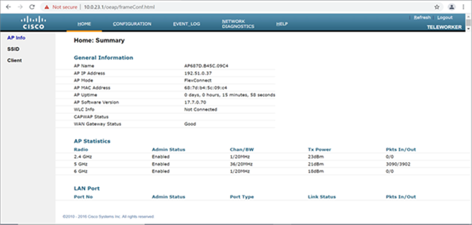
The main page of the Catalyst 9136I in Site Survey mode
These configurations include channel number, channel width, Tx power, SSID, and data rates.
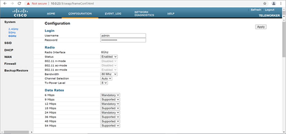
Configuration page of the Catalyst 9136I in Site Survey mode
Refer to the steps below to convert a Catalyst 9136I AP into Site Survey mode:
Change the AP to Site Survey mode (Run command on the AP’s CLI):
ap-type site-survey
After booting up, the AP is automatically assigned a static IP of 10.0.23.1.
The AP will start broadcasting the C9136_site_survey SSID with open authentication security.
Connect your wireless client with the C9136_site_survey SSID, and it will receive an IP from 10.0.23.0/24.
Access the Catalyst 9136I’s Site Survey WebUI via 10.0.23.1.
The first time the default username and password is admin/admin, you will be directed to resetting that insecure password on the first log-in
When done, convert your AP back to CAPWAP mode to join the controller again (AP CLI):
ap-type capwap
Note: If an AP is converted into Site Survey mode while connected to a CONTROLLER, it will disjoin and go into standalone mode.
The Catalyst 9136I has an internal hexa-radio architecture designed for omnidirectional RF propagation. Refer to the following figures for the different antenna patterns.
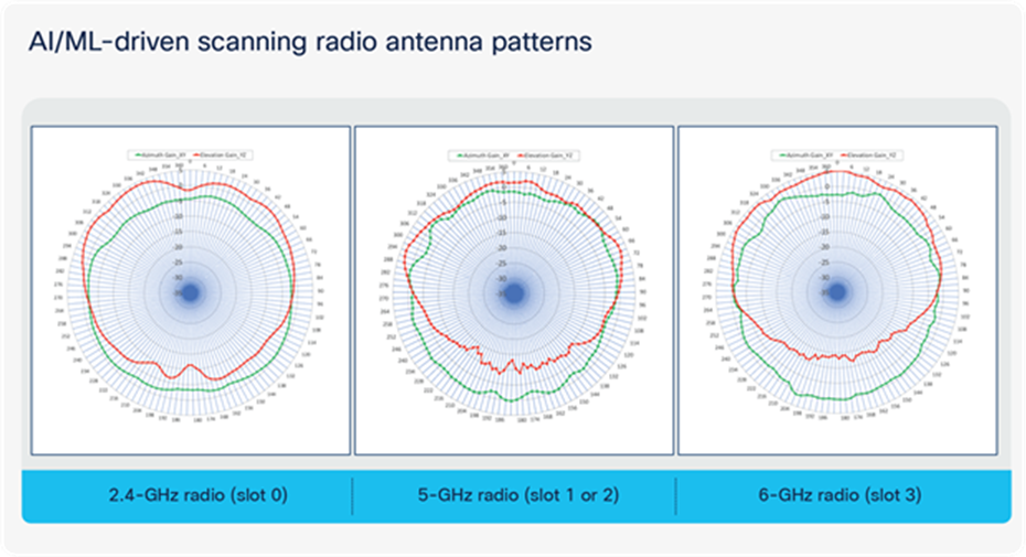
AI/ML-driven scanning radio antenna patterns
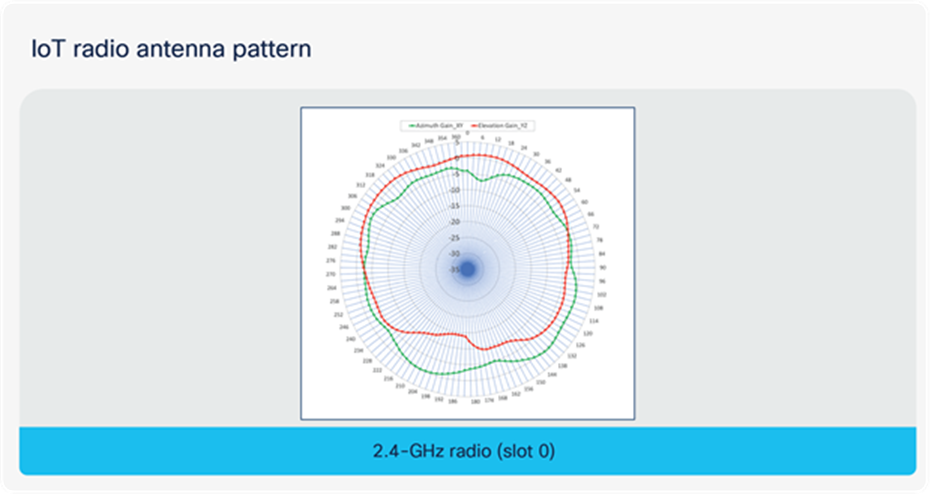
IoT radio antenna pattern
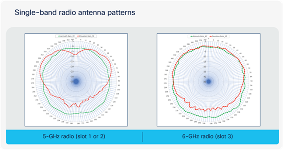
Single-band radio antenna patterns
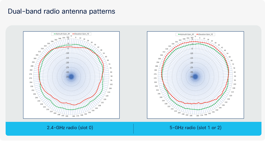
Dual-band radio antenna patterns
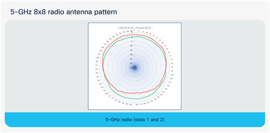
5-GHz 8x8 radio antenna pattern
Software solution compatibility
This section depicts the software features and their compatible versions with the Cisco Catalyst 9136I.
Table 11. Catalyst 9136I feature release timelines
Catalyst 9136I feature release timelines
| Feature |
Cisco IOS® XE Version |
Cisco Catalyst Center version |
Cisco Spaces Connector version |
Note |
| Concurrent 4x4: 4SS 5-GHz radios (slots 1 and 2) |
17.9.x |
N/A |
N/A |
In 17.7.1, only slot 1 can be enabled in 8x8 or 4x4 mode, while slot 2 is administratively disabled. |
| FastLocate |
17.9.1 |
N/A |
N/A |
|
| Temperature, humidity, air quality sensors |
17.8.1 |
N/A |
2.3.2 |
|
| Spectrum analysis (iCAP) |
17.8.1 |
2.3.3 |
N/A |
|
| Rogue management with AI/ML-driven scan radio |
17.8.1 |
2.3.3 |
N/A |
Rogue management with serving radios is supported in 17.7.1. |
| aWlPS with AI/ML-driven scan radio |
17.8.1 |
2.3.3 |
N/A |
aWlPS with serving radios is supported in 17.7.1. |
| BLE |
17.8.1 |
N/A |
N/A |
|
| Application Hosting |
17.8.1 |
2.3.2 |
N/A |
|
| Zero-wait DFS |
Roadmap |
N/A |
N/A |
|
| AI-enhanced RRM (6 GHz) |
Roadmap |
Roadmap |
N/A |
|
| Mesh |
Roadmap |
Roadmap |
N/A |
|
| Workgroup Bridge (WGB) |
Not planned |
Not planned |
Not planned |
|
Note: Any features not listed in the figure above are released with Cisco IOS XE 17.7.1.
Table 12. Cisco software solution stack compatibility matrix for all APs
Access point software stack
Software support matrix (minimum support)
| Access points |
Cisco IOS® XE |
AireOS |
Cisco Catalyst Center |
Cisco Primes® |
CMX |
Cisco Spaces |
ISE |
| Catalyst® 9136I |
17.7.1 |
N/A |
2.3.2 |
3.10 |
10.6.3-75 |
2.3.2 Connector |
2.6 |
| Catalyst 9130AXE |
17.1.1 |
8.10MR1 |
1.3.2 |
3.7 |
10.6.2 |
2.3.2 Connector |
2.3 2.4 2.6 |
| Catalyst 9130AXl |
16.12.1s with AP DP |
8.10 |
1.3.1.2 |
3.7 |
10.6.2 |
2.3.2 Connector |
2.3 2.4 2.6 |
| Catalyst 9120AXE, 9120AXP |
16.12.2 |
8.10 |
1.3.2 |
3.7 |
10.6.2 |
2.3.2 Connector |
2.3 2.4 2.6 |
| Catalyst 9115AX, 9120AXl |
16.12.1s |
8.9.111 |
1.3.1.2 |
3.7 |
10.6.2 |
2.3.2 Connector |
2.3 2.4 2.5 |
| Catalyst 9105AX Series |
17.3 |
8.10 (MR3) |
2.1.2.0 |
3.9 |
10.6.2 (MR2) |
2.3.2 Connector |
2.4 2.6 2.7 |
| Wave 2 access points |
16.12.1s |
8.5MR5 |
1.3.1.2 |
3.7 |
10.6.2 |
2.3.2 Connector |
2.3 2.4 2.6 |
Table 13. Wireless Assurance compatibility matrix for the Catalyst 9136I
Wireless Assurance
Software and hardware matrix (minimum support)
| Feature |
Cisco Catalyst Center |
Controller hardware |
Controller software |
AP modes |
| Network Assurance |
2.3.2 |
AireOS |
N/A |
N/A |
| Cisco IOS® XE |
17.7.1 |
Local, Cisco FlexConnect®, fabric |
||
| Application Experience |
2.3.2 |
AireOS |
N/A |
N/A |
| Cisco IOS XE |
17.7.1 |
Local
(FlexConnect and fabric support are on roadmap)
|
||
| Application Visibility |
2.3.2 |
AireOS |
N/A |
N/A |
| Cisco IOS XE |
17.7.1 |
Local, FlexConnect, fabric |
||
| Rogue* |
2.3.3 |
AireOS |
N/A |
N/A |
| Cisco IOS XE |
17.8.1 |
Local, FlexConnect, fabric |
||
| aWIPS*(with CleanAir) |
2.3.3 |
AireOS |
N/A |
N/A |
| Cisco IOS XE |
17.8.1 |
Local, FlexConnect, fabric |
||
| Wi-Fi 6 dashboard |
2.3.2 |
AireOS |
N/A |
N/A |
| Cisco IOS XE |
17.7.1 |
Local, FlexConnect, fabric |
Table 14. Wireless Assurance compatibility matrix for the Catalyst 9136I continued
Wireless Assurance (cont.)
Software and hardware matrix (minimum support)
| Feature |
Cisco Catalyst Center |
Controller hardware |
Controller software |
AP modes |
| Wireless Network Service Analytics |
2.3.2 |
AireOS |
N/A |
N/A |
| Cisco IOS® XE |
17.7.1 |
Local, Cisco FlexConnect®, fabric |
||
| Wireless 3D Analyzer |
2.3.2 |
AireOS |
N/A |
Local, Cisco FlexConnect, fabric |
| Cisco IOS XE |
17.7.1 |
Local, Cisco FlexConnect, fabric |
||
| True Trace |
2.3.2 |
AireOS |
N/A |
Local, Cisco FlexConnect, fabric |
| Cisco IOS XE |
17.7.1 |
Local, Cisco FlexConnect, fabric |
||
| Webex 360 |
2.3.2 |
AireOS |
N/A |
Local, Cisco FlexConnect, fabric |
| Cisco IOS XE |
17.7.1 |
Local, Cisco FlexConnect, fabric |
Table 15. AI Network Analytics compatibility matrix for the Catalyst 9136I
AI Network Analytics
Software and hardware matrix (minimum support)
| Feature |
Controller hardware |
Controller software |
Cisco Catalyst Center |
AP modes |
| AI-driven issues |
AireOS |
N/A |
N/A |
Local, Cisco FlexConnect®, fabric |
| Cisco IOS® XE |
17.7.1 |
2.3.2.0 |
||
| Network insights |
AireOS |
N/A |
N/A |
|
| Cisco IOS XE |
17.7.1 |
2.3.2.0 |
||
| Heatmaps |
AireOS |
N/A |
N/A |
|
| Cisco IOS XE |
17.7.1 |
2.3.2.0 |
||
| Peer comparison |
AireOS |
N/A |
N/A |
|
| Cisco IOS XE |
17.7.1 |
2.3.2.0 |
||
| Network comparison (previously called site comparison) |
AireOS |
N/A |
N/A |
|
| Cisco IOS XE |
17.7.1 |
2.3.2.0 |
||
| AI-driven baselines |
AireOS |
N/A |
N/A |
|
| Cisco IOS XE |
17.7.1 |
2.3.2.0 |
Table 16. Intelligent Capture compatibility matrix for the Catalyst 9136I
Intelligent Capture
Software and hardware matrix (minimum support)
| Feature |
Cisco Catalyst Center |
Controller hardware |
Software version |
| Anomaly packet capture scheduled packet capture AP and client statistics |
2.3.2 |
AireOS |
N/A |
| Cisco IOS® XE |
17.7.1 |
||
| Data packet capture |
2.3.2 |
AireOS |
N/A |
| Cisco IOS XE |
17.7.1 |
||
| Spectrum Analysis |
2.3.2 |
AireOS |
N/A |
| Cisco IOS XE |
17.8.1 |
Table 17. Wireless automation compatibility matrix for the Catalyst 9136I
Wireless Automation
Software and hardware matrix (minimum support)
| Feature |
Cisco Catalyst Center |
Controller hardware |
Controller software |
AP modes |
| Wireless provisioning |
2.3.2 |
AireOS |
N/A |
Local, Cisco FlexConnect®, fabric |
| Cisco IOS® XE |
17.7.1 |
|||
| Cisco Umbrella® |
2.3.2 |
AireOS |
N/A |
|
| Cisco IOS XE |
17.7.1 |
|||
| Cloud Device Provisioning application |
2.3.2 |
AireOS |
N/A |
|
| Cisco IOS XE |
17.7.1 |
|||
| SD-Access* |
2.3.2 |
AireOS |
N/A |
|
| Cisco IOS XE |
17.7.1 |
|||
| Wide Area Bonjour |
2.3.2 |
AireOS |
N/A |
|
| Cisco IOS XE |
17.7.1 |
|||
| User Defined Network (UDN) |
2.3.2 |
AireOS |
N/A |
|
| Cisco IOS XE |
17.7.1 |
Table 18. Wireless automation compatibility matrix for the Catalyst 9136I continued
Wireless Automation (cont.)
Software and hardware matrix (minimum recommended support)
| Feature |
Cisco Catalyst Center |
Controller hardware |
Controller software |
AP modes |
| Command Runner |
2.3.2 |
AireOS |
N/A |
Local, Cisco FlexConnect®, fabric |
| Cisco IOS® XE |
17.7.1 |
|||
| AP Plug and Play |
2.3.2 |
AireOS |
N/A |
|
| Cisco IOS XE |
17.7.1 |
|||
| Software Image Management (SWIM) |
2.3.2 |
AireOS |
N/A |
|
| Cisco IOS XE |
17.7.1 |
|||
| Cisco®Secure Network Analytics |
Roadmap |
AireOS |
N/A |
|
| Cisco IOS XE |
17.7.1 |
|||
| Application hosting |
2.3.2 |
AireOS |
N/A |
|
| Cisco IOS XE |
17.7.1 |
|||
| Application policy |
2.3.2 |
AireOS |
17.7.1 |
|
| Cisco IOS XE |
N/A |
|||
| Ekahau integration |
Roadmap |
AireOS |
Roadmap |
|
| Cisco IOS XE |
17.7.1 |
|||
| Security advisories |
2.3.2 |
AireOS |
N/A |
|
| Cisco IOS XE |
17.7.1 |
Table 19. Policy application compatibility matrix for the Catalyst 9136I
Policy Application
Software and hardware matrix (minimum support)
| Feature |
Cisco Catalyst Center |
Controller hardware |
Controller software |
AP modes |
| Group-based access control |
2.3.2 |
AireOS |
N/A |
Local, Cisco FlexConnect®, fabric |
| Cisco IOS® XE |
17.7.1 |
|||
| AI Endpoint Analytics |
2.3.2 |
AireOS |
N/A |
|
| Cisco IOS XE |
17.7.1 |
|||
| Group-based policy analytics |
2.3.2 |
AireOS |
N/A |
|
| Cisco IOS XE |
17.7.1 |
|||
| Policy analytics dashboard |
2.3.2 |
AireOS |
N/A |
|
| Cisco IOS XE |
17.7.1 |
● Catalyst 9800 Deployment Guide
YouTube Series:
● Catalyst 9136I Basement Series (Nicholas Swiatecki, PM): https://youtu.be/8XgikEgnkOc
● Catalyst 9136I Unboxing Video (Richard Jang, TME): https://youtu.be/X8r_AmnUNEg
● As the Expert (Jim Florwick, TME): https://www.youtube.com/watch?v=1WZeP_jdl4Y
● Speed test: https://youtu.be/r793YCWdwnw
● Application Experience: https://youtu.be/VfR4M2y64Zs
● Port redundancy: https://youtu.be/3MeLvQLyaHg
● Rogue and aWIPS: https://youtu.be/tiY7jBau4lg
● AI-enhanced RRM: https://youtu.be/rPpfw3P2Cls