Cisco Aironet Active Sensor Deployment Guide 2.2.1
Available Languages
Bias-Free Language
The documentation set for this product strives to use bias-free language. For the purposes of this documentation set, bias-free is defined as language that does not imply discrimination based on age, disability, gender, racial identity, ethnic identity, sexual orientation, socioeconomic status, and intersectionality. Exceptions may be present in the documentation due to language that is hardcoded in the user interfaces of the product software, language used based on RFP documentation, or language that is used by a referenced third-party product. Learn more about how Cisco is using Inclusive Language.
- US/Canada 800-553-2447
- Worldwide Support Phone Numbers
- All Tools
 Feedback
 Feedback
Overview of the Cisco Aironet Active Sensor
Enterprise wireless networks are a rapidly growing part of today’s age of technology. They are becoming more mission critical each day as additional companies migrate to wireless solutions as a means to run their business. As wireless networks grow exponentially, so does their complexity, and thus it’s important to be able to quickly identify and resolve potential connectivity issues before degradation occurs. While this applies to all networks, it is especially true in remote facilities where IT professionals may not be onsite. A consistent solution is needed that can take on this network health assessment role. To address these pain points, Cisco has created an intent-based networking and network analytics solution, the Cisco® Aironet® Active Sensor, together with Cisco DNA Assurance.
The Aironet Active Sensor is a state-of-the-art wireless device that functions like a regular WLAN client, but has the ability to continuously collect various metrics that determine the health and effectiveness of a wireless network. This data is then analyzed for issues and sent to Cisco DNA Assurance, where it can be displayed graphically for intuitive interpretation by the user.
Cisco DNA Assurance is an enterprise-grade intent-based networking software application that allows a user to easily configure, monitor, and troubleshoot the health of their network. It has numerous features and use cases; however, the primary focus in this deployment guide will be on its Proactive Health Assessment feature, together with the Aironet Active Sensor.
Together, the sensor and Cisco DNA Assurance provide users with around-the-clock feedback related to any weakness in the network so that any issues can be mitigated before they become serious. Since this is a software-centric solution, the moment the sensors are deployed onsite, users will have immediate access to an in-depth visualization of their network’s health from anywhere in the world.
This document covers the deployment of the Cisco Aironet Active Sensor together with Cisco DNA Assurance.
Recommended Software
● Cisco DNA Center Software Release 2.2.1.0
● Aironet Active Sensor Software Release 2.2.1.0
Note: This document is based on the software releases recommended above. Certain features described in this deployment guide are not supported for earlier software releases.
Table 1. Aironet Active Sensor and Cisco DNA Center software matrix
| Sensor software release |
Cisco DNA Center software release |
| 2.2.2.0 |
2.2.2.0 |
| 2.2.1.0 |
2.2.1.0 |
| 2.1.2.0 |
2.1.2.0 |
| 2.1.1.0 |
2.1.1.0 |
| 1.3.3.0 |
1.3.3.x |
| 1.3.1.2 |
1.3.1.2 or later 1.3.1.x |
| 8.8.263.0 |
1.3.0.3 or earlier (example: 1.2.x) |
Note: The sensor device-side software release must match the Cisco DNA Center software for proper compatibility.
Prerequisite: Installing sensor packages from the Cisco DNA Center
Cisco DNA Center provides the option to download separate sensor packages called Assurance - Sensor and Automation - Sensor. You will be able to download and install these packages on top of the base Cisco DNA Center software.
1. To install the sensor packages, log in to Cisco DNA Center and open the hamburger menu in the top left corner.
2. Click System > Software Updates, then click Installed Apps on the left. Scroll down to Assurance and you will find the packages available there for download or install (Figure 1).
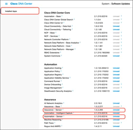
Location of the Assurance – Sensor and Automation – Sensor packages
Aironet Active Sensor hardware
Description: The Aironet Active Sensor is a small-form-factor, dedicated hardware-based wireless sensor that can be powered in many different ways through a small sliding module that inserts into the sensor (Figure 2).
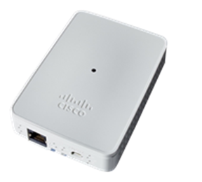
Aironet Active Sensor hardware
Technical specifications
● Purpose-built wireless sensor for Cisco DNA Assurance
● 2x2 radio with two spatial streams
● 802.11ac Wave 2 wireless capabilities
● Multiple power options:
● 802.3af PoE module
● Micro USB Type B connector (2.5A/5V)
● AC wall socket adapter
● Small form factor (WxLxH):
● 3.25 x 4.75 x 0.75 in. (85 x 119 x 24 mm)
Without a Power over Ethernet (PoE) module, power can be supplied from a local 2.5A/5V USB port, using a micro USB Type B connector. (There is a USB Type C connector, but it is dedicated for the PoE module connection.) Additionally, there are modules that allow for a direct AC power supply, as well as PoE operation (Figure 3).
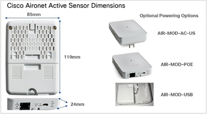
Rear view of sensor and powering options
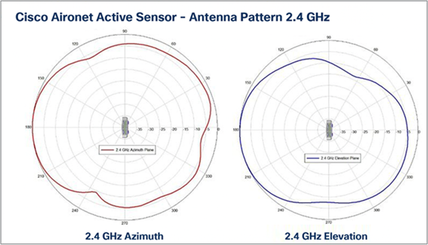
Antenna patterns, 2.4 GHz
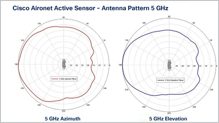
Antenna patterns, 5 GHz
Table 2. Aironet Active Sensor and accessory product IDs
| Product |
Product ID |
| Aironet Active Sensor |
AIR-1800S-x-K9 |
| PoE with 1G Ethernet module |
AIR-MOD-SPOE |
| USB adapter power module – US plug only |
AIR-MOD-USB-US= |
| USB adapter power module – rest of world |
AIR-MOD-USB-RW= |
| Wall-mount bracket kit |
AIR-AP-BRAKET-NS |
| Aironet Active Sensor console cable |
AIR-CONSADPT= |
| AC adapter power module |
AIR-MOD-AC-US |
Description: The ideal deployment location for sensors is wall-mounted at desktop height, between 22 and 47 inches (56 and 120 cm) from the floor. However, in addition to being wall mounted, the sensor can be mounted on a desk or ceiling.
● Due to its small size, the sensor uses a specially designed metal-based wall-mount bracket (part number AIR-AP-BRACKET-NS) (Figure 6).
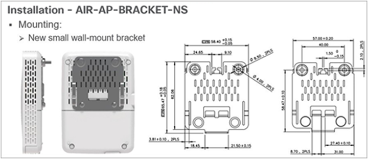
Wall-mounting the sensor
The Aironet Active Sensor simulates a wireless client and automatically associates to the nearest access point (AP) based on the received signal strength indicator (RSSI). It can be configured to test up to five APs per test cycle consecutively. For example, if a single floor has 40 APs, the administrator should deploy at least eight sensors to that floor to have maximum sensor coverage. By default, the sensor targets the user-defined SSID automatically based on whichever SSID has the highest RSSI; however, there is also an option to specify specific APs for the sensor to target. (This option is discussed later in the deployment guide [see Figure 82]).
As shown in Figure 7 below, a typical sensor deployment should have between one and five APs per sensor.
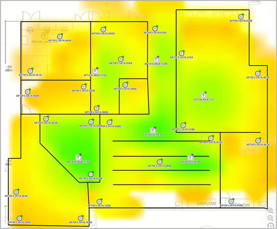
Sensor and AP floor map deployment
Sensor deployment checklist
This deployment guide describes in detail each step in the deployment checklist shown in Figure 8.

Sensor deployment steps
Day 0: Plan sensor deployment
1. Plan the number of sensors that will be deployed per site and the location.
To determine the number of sensors to deploy and their position of deployment, you must consider the following.
● During each test cycle, the sensor can test up to five surrounding APs with the highest RSSI. This means that you must first analyze each location’s floor map to determine which potential sensor deployment locations will allow every AP on the floor to be tested.
● Determine the scope of your wireless tests from a frequency perspective, and take into consideration whether you plan to test just 2.4 GHz, just 5 GHz, or both. A 2.4-GHz signal will have a greater range than 5 GHz, and the sensor deployment may differ based on how your network is configured.
● Pay attention to each floor’s physical layout and where the RF signal can easily travel vs. where it cannot reach. For example, if your building has many solid walls or areas that easily reflect RF signals, take this into account during the planning phase. Consider visiting the potential sites of deployment and analyzing whether you’re able to see each of the broadcasted SSIDs/BSSIDs from each of the APs you’d like to test. If you’re able to see all of these SSIDs/BSSIDs within the RSSI range you plan to configure, this could be an ideal location for sensor testing.
● Remember that the purpose of the Aironet Active Sensor is to test the wireless network from the perspective of a client. While all prior points are critical, it is also essential to place your sensors in a location where laptops or phones would typically be used. For example, placing a sensor in an area where a large number of employees work would be more beneficial in understanding the effectiveness of your wireless network than putting the sensor in an area where there is no one.
2. Configure the network infrastructure necessary for sensor deployment and testing.
a. Create a VLAN planned for sensor use on a switch that can reach Cisco DNA Center.
b. Configure a Dynamic Host Configuration Protocol (DHCP) or DNS server for the created VLAN, and include Plug and Play (PnP) discovery method details (option 43 or pnpserver.<domain name>.com DNS entry, e.g., pnpserver.cisco.com) to allow the sensor to discover Cisco DNA Center during provisioning.
c. Optional planned PnP: Create and claim PnP profiles on Cisco DNA Center for the sensors you plan to install on day 1.
d. Prepare the sensor test target servers such as AAA, email, and FTP, and ensure that the sensor device network has direct access to these.
e. Create and deploy a sensor test template to the desired sites in Cisco DNA Center.
f. Option 1 – Wired backhaul: Set up a wired network between the sensor and Cisco DNA Center.
Note: 802.1X wired backhaul is supported. For more information, refer to the section “Creating a sensor backhaul profile in Cisco DNA Center.”
g. Option 2 – Wireless backhaul: Create a CiscoSensorProvisioning SSID on the wireless controller.
Note: 802.1X wireless backhaul is supported. For more information, refer to the section “Creating a sensor backhaul profile in Cisco DNA Center.”
Note: Wireless backhaul for Fabric is not supported in Fabric mode.
Day 1: Deploy sensor hardware
1. Install the sensors in the planned locations.
a. Connect the sensors through PoE, USB, or AC (depending on whether you’re planning to use a wired or wireless backhaul) to have them begin PnP discovery to Cisco DNA Center once they receive IP addresses from the DHCP server.
b. Once the sensor appears in the PnP page of Cisco DNA Center, claim the sensor to a site and verify on the sensor list page that the claim was successful.
c. Optional image upgrade: If the sensors are not running the latest image, mark the latest image within the Software Images page as the golden image, then upgrade the sensors through the Inventory page.
2. If not already assigned on day 0, create and assign test templates to specific sites or sensors to begin testing.
Day 2: Assess network health
1. Observe the sensor test results through the Wireless Sensors dashboard and Sensor 360 page.
a. Troubleshoot any sensor issues using the Sensor 360 page’s event log feature.
Description
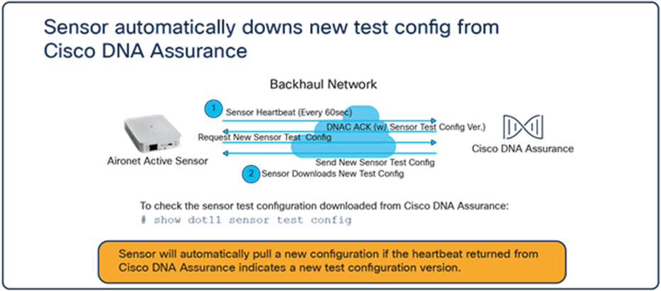
● This section covers a new concept known as the backhaul, which is the communication network the sensor uses to communicate with Cisco DNA Center.
● The sensor receives the test suite configuration directly from Cisco DNA Center (Figure 9).
● Sensor test results traverse directly from the sensor to Cisco DNA Center (Figure 10).
Sensor test configuration data flow
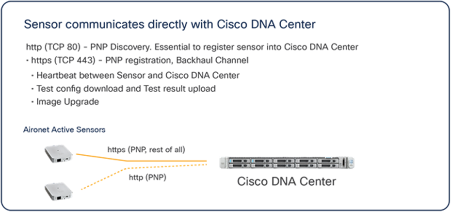
Network port between sensor and Cisco DNA Center
Description: The sensor is not an AP, but rather a dedicated wireless client simulating real client behavior; therefore, it actually operates independently from the wireless controller. It depends on Cisco DNA Center for provisioning, configuration, operation, monitoring, and upgrade.
● DHCP option 43: Through the sensor’s built-in PnP agent, the device will automatically connect to Cisco DNA Center by leveraging the DHCP option 43 field as part of DHCP OFFER from the DHCP server.
Note: The option 43 string contains a list of parameters that the sensor’s PnP agent uses to discover Cisco DNA Center. One of these parameters is the enterprise IP address of Cisco DNA Center.
● DNS: If the sensor fails to receive the IP address of Cisco DNA Center from the option 43 string, the sensor’s PnP agent will make a DNS query to the predefined hostname, PNPSERVER.
Note: If a domain name is configured within the DHCP server, the DNS query will use that domain name and make a Fully Qualified Domain Name (FQDN) query.
Example: If the domain name is configured to be cisco.com, the DNS query will be to PNPSERVER.cisco.com.
● CLI: The last resort is a manual command entered using the command-line interface (CLI) through the console or Secure Shell (SSH) protocol.
Note: Provisioning 1800S through wireless backhaul on Catalyst 9800-CL Controller using WLAN: CiscoSensorProvisioning is not supported. Please use wired backhaul to onboard 1800S on the Catalyst 9800-CL Controller.
Preparation: Network connectivity between sensors and Cisco DNA Center
For correct sensor operation, direct network connectivity is required between the sensor and Cisco DNA Center. This network connectivity from the sensor is called the backhaul interface (which can be wired or wireless). Sensors use this backhaul interface to communicate with Cisco DNA Center, which requires direct connectivity using HTTP (TCP 80) and HTTPS (TCP 443). A proxy is not supported.
Wired backhaul environment
When the sensor is equipped with a PoE module (AIR-MOD-POE=), the sensor can receive power from the PoE switch port using the 802.3af standard. The sensor can also establish a connection to Cisco DNA Center through this wired PoE interface using the wired IP address for communication. This type of sensor network configuration is called wired backhaul.
Wireless backhaul environment
If the sensor either (1) does not receive an IP address from the wired interface or (2) does receive an IP address from the wired interface but cannot discover Cisco DNA Center, it switches to the wireless backhaul as a second option to search for and connect to Cisco DNA Center (Figure 11). For this wireless backhaul option, the administrator must assign a sensor profile during the sensor PnP claiming step. In an SD-Access/fabric environment, the fabric edge that serves the sensor connection has a maximum transmission unit (MTU) that is automatically configured to 9100.
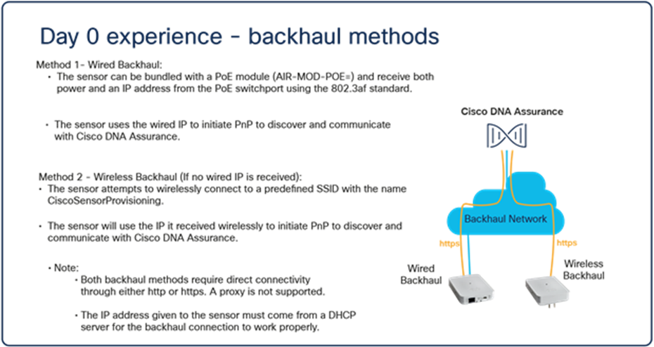
Sensor backhaul network types
Note: The wireless backhaul shares the radio interface with the wireless testing radio; however, if testing is going on for the 2.4-GHz radio, the backhaul will change to the 5-GHz radio and vice versa.
Day-0, factory-installed SSID between sensor and Cisco AP
Out of the box, the sensor must be able to associate and communicate with Cisco DNA Center. This is relatively easy if the sensor has a wired Ethernet connection. If it does not have an Ethernet connection but only the power to boot up, the sensor cannot connect to any AP.
To solve this problem, the AP and sensor use a factory-installed SSID named CiscoSensorProvisioning. This SSID is known to both the wireless controller and the sensor from a factory shipment level.
● The CiscoSensorProvisioning SSID is designed to connect the sensor to Cisco DNA Center.
● The CiscoSensorProvisioning SSID uses 802.1X and Extensible Authentication Protocol – Transport Layer Security (EAP-TLS) as its sensor device authentication and encryption mechanism.
● The wireless controller enables the CiscoSensorProvisioning SSID and assigns it to one of the first 16 WLAN SSIDs.
● The CiscoSensorProvisioning SSID can be used in Cisco FlexConnect® environments, but in such cases, it can be used only in a central switching SSID.
Note: The default CiscoSensor Provisioning SSID is only compatible to connect to sensors running software version 1.3.3.x+. To provision sensors with software versions before 1.3.3.x, create a custom wireless backhaul on DNA Center which is shown in the disclaimer after Figure 58.
Configuring the sensor backhaul SSID for AireOS WLCs
1. Create a backhaul SSID with the predefined CiscoSensorProvisioning name (Figure 12).
● This is a special-purpose, hidden SSID that is designed to connect to the sensor wirelessly.
● The sensor can connect to the Cisco AP and use it to reach Cisco DNA Center.
● The CiscoSensorProvisioning SSID uses any available WLAN ID from among the first 16 WLAN IDs. If WLAN IDs 1 to 16 are all in use, CiscoSensorProvisioning SSID creation fails.
Aironet Active Sensor day-0 provisioning configuration on the WLC
Note: Disregard the “Backhaul Configuration” section within the controller; this portion is configured from Cisco DNA Center.
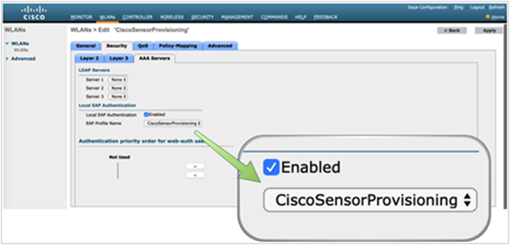
a. Enable the local EAP server with EAP-TLS to authenticate the sensor’s embedded certificate (Figure 13).
Aironet Active Sensor provisioning SSID
Note: This SSID enables a local authentication profile that is created automatically when you specify the CiscoSensorProvisioning SSID.
b. Ensure that the SSID and local authentication profiles have now been created (Figure 14).
Local authentication profile assigned to the CiscoSensorProvisioning SSID
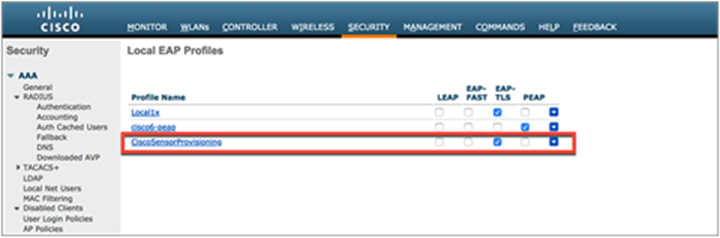
Local authentication profile for Aironet Active Sensor provisioning
Note:
● The sensor authenticates with the controller using a built-in Manufacturer Installed Certificate (MIC) with EAP-TLS (Figure 15); however, there is an option to use a custom certificate by defining and pushing a new backhaul profile in Cisco DNA Center.
● The CiscoSensorProvisioning SSID does not broadcast the SSID over the air; instead, it’s hidden by default, but the sensor can still discover and connect to it.
● The network administrator can allocate the CiscoSensorProvisioning SSID to various AP groups, making the CiscoSensorProvisioning SSID available only to specific locations.
● When using a wireless backhaul method, you MUST keep the CiscoSensorProvisioning SSID enabled at all times; otherwise, your sensor will lose connection with Cisco DNA Center.
Configuring the sensor backhaul SSID for Cisco IOS XE WLCs
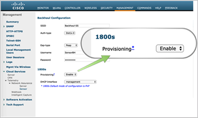
1. For Cisco Catalyst® 9800 Series devices, the CiscoSensorProvisioning SSID is enabled from Configuration > Services > Cloud Services > Network Assurance > Provisioning: ENABLED (Figure 16).
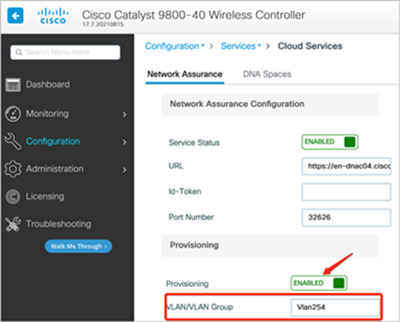
Location of Provisioning button on the 9800 Series WLC
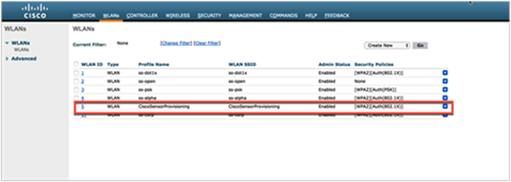
2. After provisioning is enabled, the network administrator can view the newly added SSID from Configuration > Tags and Profiles > WLANs (Figure 17).
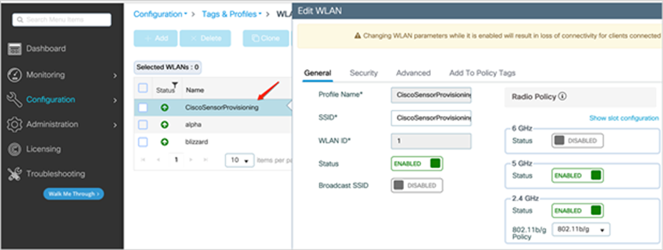
Viewing the CiscoSensorProvisioning WLAN
3. Add the policy tag to the WLC by going to Configuration > Tags and Profiles > Tags, edit current Policy Tag which is used for other SSIDs, add CiscoSensorProvisioning WLAN Profile with CiscoSensorProvisioning Policy Profile (Figure 18).
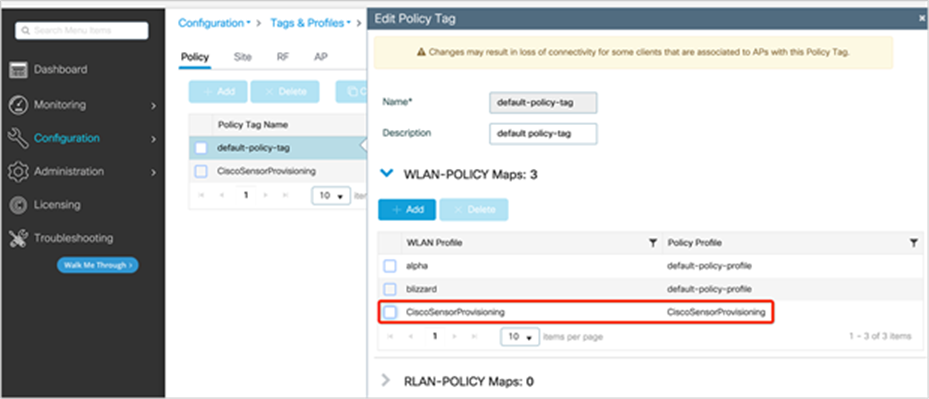
Adding the policy tag to the CiscoSensorProvisioning policy profile
4. After adding the policy tag, edit the tag to input the VLAN interface of the SSID by going to Configuration>Tags and Profiles>Policy, edit CiscoSensorProvisioning Policy Profile, go to Access Policies tab, in the VLAN section add VLAN/VLAN Group (Figure 19).
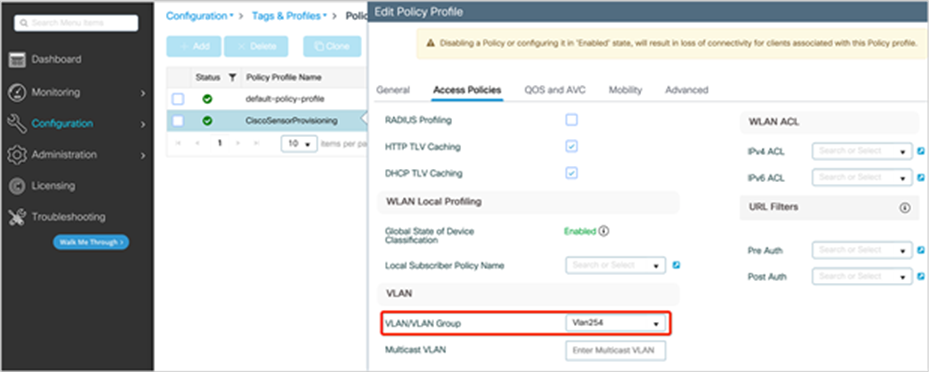
Enable the VLAN for the CiscoSensorProvisioning policy profile
Note:
● Unlike AireOS, the Cisco IOS® XE-based Cisco Catalyst 9800 Series does allow configuration changes for the CiscoSensorProvisioning SSID. However, we do not recommend that you change the configuration, as doing so can break compatibility with the sensor.
● When using a wireless backhaul method, you MUST keep the CiscoSensorProvisioning SSID enabled at all times; otherwise, your sensor will lose connection with Cisco DNA Center.
Configuring the sensor backhaul SSID on Cisco DNA Center for AireOS or Catalyst 9800
You can automate and configure a Wireless Backhaul Network for Sensors on Wireless Controllers and APs via Cisco DNA Center starting Cisco DNA Center version 2.2.1. This will allow you to enable the sensor backhaul ssid without having to go into the wireless controller to manually turn on the sensor backhaul SSID.
Known Limitations:
This feature is not supported on any Fabric in the Box deployments in SDA or on the Embedded Wireless Controller on the Access Point, The controller is required to have to be centrally switched to work.
1. Create a new Wireless SSID in Network Settings in Cisco DNA Center
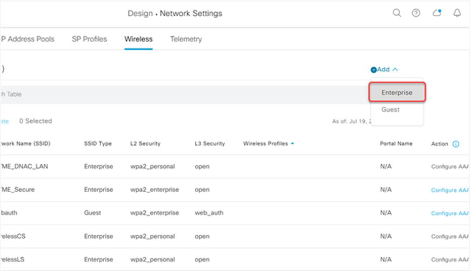
Adding a new Enterprise SSID on Cisco DNA Center
2. Select the Sensor Setting to enable the Sensor Backhaul SSID
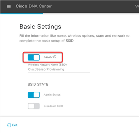
Enable the Sensor feature for the SSID
3. Configure the SSID Profile Settings
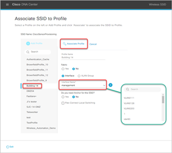
Associate the SSID to a current profile on Cisco DNA Center
Customizable Components Sensor SSID Creation:
1. Network Profile –
◦ Interface: The interface for the SSID can be assigned within the GUI which allow for changing in VLANs and
◦ Site: The Network Profile can be added to specific sites
2. Central Switching:
◦ The CiscoSensorProvisioning SSID uses central switching so Wireless Backhaul traffic will be terminated centrally and will get an IP address from central location.
Certificate management with SCEP
Description: The Simple Certificate Enrollment Protocol (SCEP) provides two main advantages during the device certificate enrollment process. The first is that it allows network devices to easily enrol for a certificate using a URL and a one-time password (the shared secret is also supported but is much less secure) to communicate with a public key infrastructure (PKI). This process is automatic as opposed to its usual manual process, which saves significant administrative time by speeding up the device certificate enrollment process. The second advantage is that automating this process removes any human intervention during the handling of security certificates, which prevents these certificates from being exposed to machines or humans, providing a genuinely secure provisioning process.
You can create a SCEP profile directly on the sensor page. This gives the Aironet Active Sensor the ability to automatically pull these certificates directly from Cisco DNA Center and provision themselves. This automated process is especially useful for large-scale deployments, as it eliminates all manual effort.
SCEP profiles can be created and managed by navigating to the hamburger menu and clicking Assurance > Manage > Sensors, and then choosing Setting > SCEP Profiles > Add SCEP Profile (Figure 23).
Create SCEP Profile page
Note: For more information about SCEP, refer to the following link: https://cs.co/scep_config
Follow the steps below to create an EAP-TLS certificate on a Windows machine to be used with SCEP:
Note: The steps below assume that your Windows Server has a certificate ready to be issued.
1. Create your SCEP certificate template on Windows.
a. Within the Windows machine that acts as your Certificate Authority, open the Run menu, and type in MMC.
b. At the top, open the File drop-down menu, and select Add/Remove Snap-in.
c. Choose Certification Authority.
d. Right-click the Certificate Template folder and click Manage.
e. Right-click the existing template User, and select Duplicate Template and provide it a unique name such as Sensors.
f. Navigate to the registry settings under Computer > HKEY_LOCAL_MACHINE > SOFTWARE > Microsoft > Cryptography > MSCEP.
g. Change the EncryptionTemplate, GeneralPurposeTemplate, and SignatureTemplate keys from the default IPsec (Offline Request) template to the new Sensors template that’s just been created.
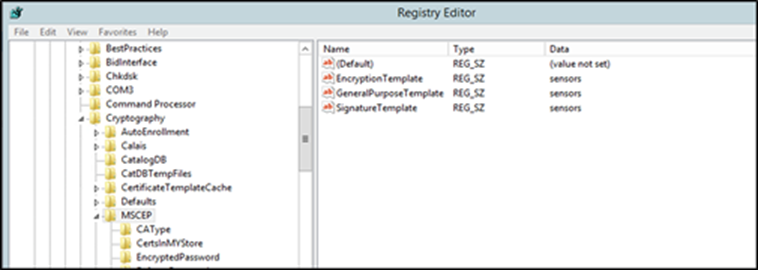
MSCEP directory within a Windows machine
Note: Any changes within the Windows registry require a server reboot for before they take effect.
2. Create a new SCEP user in Windows.
a. Open the Start menu.
b. Select Administrative tools.
c. Select Active Directory Users and Computers.
d. Expand the domain, right-click the Users folder, and select New Object > User.
e. Input the new user information, then click Next until the process completes.
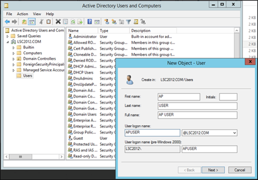
Creating a new SCEP user within Active Directory Users and Computers.
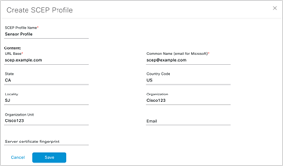
3. Create your SCEP profile in Cisco DNA Center.
a. Within Cisco DNA Center, open the menu and navigate to Assurance > Manage > Sensors, (under Manage) > Setting > SCEP Profiles.
b. Fill in the SCEP profile information using the referencing the data and screen shot below:
● URL Base for Windows Server: http://<CA server IP/domain>/certsrv/mscep/mscep.dll
Example: https://90.0.0.4/certsrv/mscep/mscep.dll
● Common Name: <User>@<CA Domain>
Example: scep@CA2012TB90.com
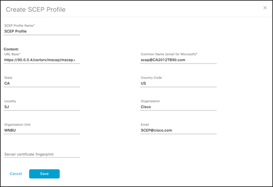
Create SCEP Profile page
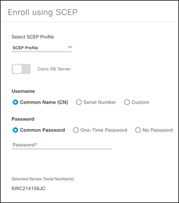
4. Enroll Aironet Active Sensors in the SCEP profile created in Cisco DNA Center.
a. Within Cisco DNA Center, open the menu and navigate to Assurance > Manage > Sensors, (under Manage).
b. Select the sensor(s) you’d like to enroll with the created SCEP profile.
c. Under the Actions drop-down menu, select Enroll using SCEP.
d. Under Select SCEP Profile, select the SCEP profile you’d like to enroll the sensor with.
e. Under Password, the following options can be selected:
● Common Password: Retrieve password from https://<CA server IP/domain>/certsrv/mscep_admin
● One-Time Password: Enter your password of choice.
● No Password: No certificate password is required.
● Note: If you’d like to change the password settings, on your Windows Server, navigate to regedit, and then to HKEY_LOCAL_MACHINE\SOFTWARE\MICROSOFT\Cryptography\MSCEP\.
Create SCEP Profile page
Cisco DNA Center discovery from the sensor
To discover Cisco DNA Center, the sensor must learn its IP address. It can do so via the following methods.
● DHCP option 43
● DNS discovery
● Configuration through the sensor’s CLI using the console cable (AIR-CONSADPT=) or SSH
DHCP option 43
The most common method of sending the IP address of Cisco DNA Center to the sensor is by packaging the IP address as part of the DHCP IP addressing process.
The network administrator uses the DHCP option 43 field to add the Cisco DNA Center IP address. The administrator enters the following ASCII-formatted string into the DHCP option 43 field:
5A1N;B2;K4;I<Cisco DNA Center IP Address>;J80
When the sensor receives its own IP address from the DHCP server, it also gets the Cisco DNA Center IP address through the DHCP option 43 field.
Sample configuration from a Cisco IOS device:
ip dhcp pool vlan30
network 30.30.0.0 255.255.0.0
default-router 30.30.0.1
dns-server 100.100.100.11
option 43 ascii 5A1N;B2;K4;I100.100.100.80;J80
By default, Cisco DNA Center uses a self-assigned certificate when initially brought up; however, there is an option to include a third-party certificate in the application. If a third-party certificate was added to the application, you need to look out for the following scenario to avoid any issues. If the Subject Alternative Name (SAN) field in the new certificate installed on Cisco DNA Center does not match the method that is given to the Aironet Active Sensor, you may run into issues during provisioning.
For example, if option 43 is used to provide PnP details to the sensor, but the Cisco DNA Center IP address is provided only in the PnP details (and is missing from the new certificate’s SAN field), the mismatch will cause issues when the sensor discovers Cisco DNA Center.
To avoid this issue, make sure that the SAN field in the new certificate contains the IP address. Alternatively, change the method used to provide PnP details for the Aironet Active Sensor.
For example, if only the IP address was used previously, change the option 43 field from:
option 43 ascii “5A1D;B2;K4;I<IP Address>;J80”
to
option 43 ascii “5A1D;B1;K4;I<FQDN>;J80”
Option 43 sample configuration on Windows Server
1. For Infoblox, under Data Management > DHCP > Networks, choose the IPv4 network and click Edit (Figure 29).
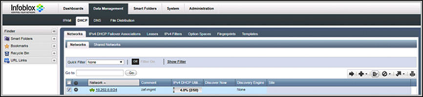
Infoblox DHCP server configuration
a. In the Custom DHCP Options area, choose DHCP and vendor-encapsulated-options (43) string. Enter the option 43 ASCII string, such as 5A1N;B2;K4;I192.168.139.141;J80 (Figure 30).
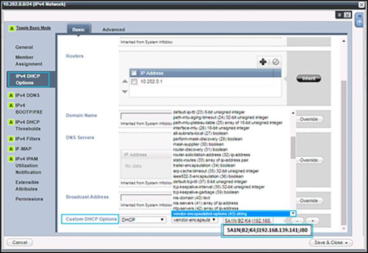
Creating an option 43 string on an Infoblox DHCP server
Note: Make sure to use uppercase letters to configure the option 43 field.
b. Conditional: If the DHCP option 43 field is already used for another purpose (such as to send the wireless controller IP address to the AP), you can configure the DHCP server to return a different option 43 message based on the client device type (Figure 31).
● To identify the client device type, validate the identifier message (DHCP option 60) within the DHCP request packet from the client (in this case, the Aironet Active Sensor).
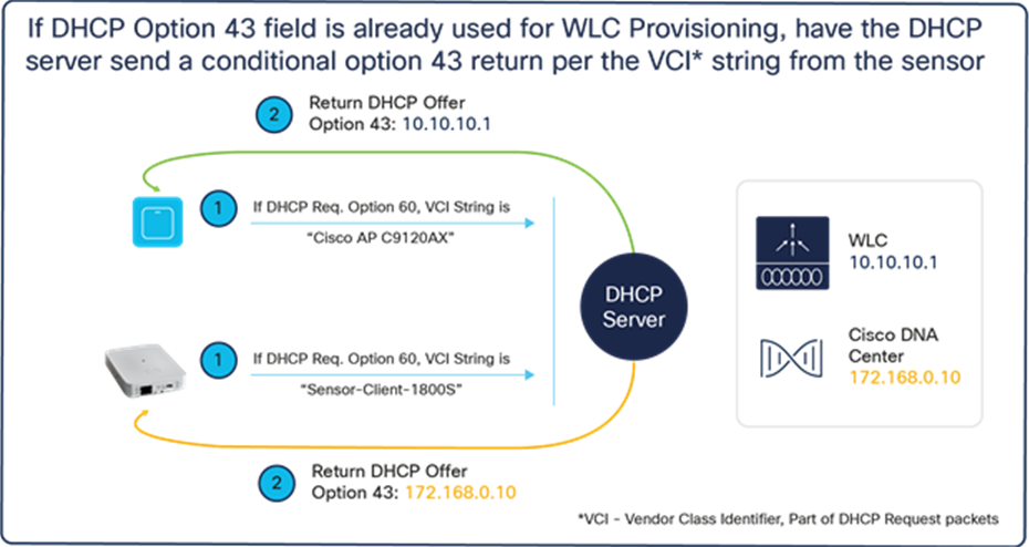
DHCP option 43 and option 60 workflow
When the sensor sends the DHCP request, it always includes the DHCP option 60 field, the Vendor Class Identifier (VCI). The VCI is a text string that uniquely identifies the vendor of the DHCP client device. The Aironet Active Sensor’s VCI string is Sensor-Client-1800S.
To use the unique VCI string, the DHCP server administrator must set up special conditional handling of the option 43 return field. The DHCP server can return different IP addresses based on the incoming VCI string.
For example, if the DHCP client includes the VCI string “Cisco AP c3800,” it means the DHCP client is an Aironet 3800 Series AP and needs to retrieve the Cisco wireless controller’s IP address part of the option 43 message. If the DHCP request message includes the VCI string “Sensor-Client-1800S,” it means the client device is an Aironet Active Sensor, and the option 43 field from the DHCP server is the Cisco DNA Center IP address.
You can find different VCI string examples at https://cs.co/vci_strings.
The sensor’s VCI strings are as follows:
● Sensor software before 1.3.3.0: Cisco AP c1800
● Sensor software 1.3.3.0 and later: Sensor-Client-1800s
To configure your Windows Server to redirect your sensor to Cisco DNA Center conditionally through the VCI string sent by the device, follow the steps below:
The steps below assume that you’ve already created (1) a DHCP pool used by both sensors and APs, and (2) an option 43 scope used by the APs for redirection to anything other than the Cisco DNA Center you would like to direct your sensors to.
1. Open your Windows DHCP server, right-click on IPv4, then click Define Vendor Classes (Figure 32).
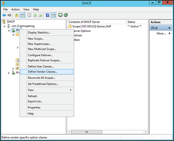
Define Vendor Classes location on Windows Server
2. Click Add, enter the following, then click OK and then Close (Figure 33).
● Display Name: Any text name to use to identify the DHCP vendor class
● Description: Information regarding the DHCP vendor class
● ASCII: The predefined VCI string of the device. In our case, the Aironet Active Sensor’s VCI string is “Sensor-Client-1800S” (use “Cisco AP c1800” if you’re on a sensor software version before 1.3.3.0).
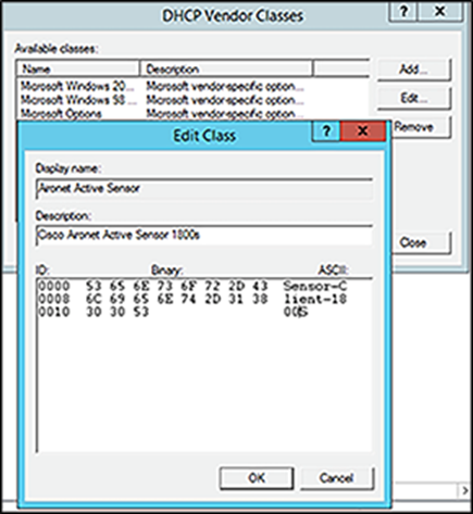
Creating a vendor class in Windows Server
3. Right-click on IPv4, then click Set Predefined Options. Open the Option class drop-down menu and select the DHCP vendor class you just created, then click Add (Figure 34).
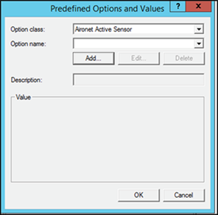
Selecting the new DHCP vendor class in Windows Server
4. A Change Option Name dialog box will appear; enter the following and click OK (Figure 35).
● Name: Any text used to identify the option type
● Data type: String
● Code: 43
● Description: Information regarding the option type
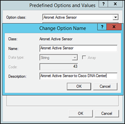
Specifying information for the option type in Windows Server
5. Within the String input field, enter the following: 5A1N;B4;K4;I<Cisco DNA Center IP>;J<Port Number>, then click OK (Figure 36).
Note: Refer to the information on option 43 PnP discovery given earlier in this section.
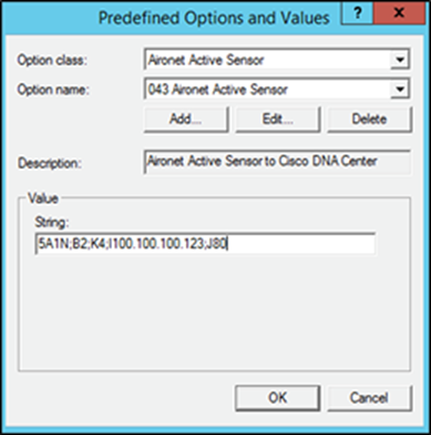
Specifying the string input for the option
6. Under your DHCP IP Scope, right-click on Scope Options and a Scope Options dialog will appear (Figure 37).
7. Click the Advanced tab, then open the Vendor Class drop-down menu and select your sensor vendor class name. Select the check box under Available Options, then click OK.
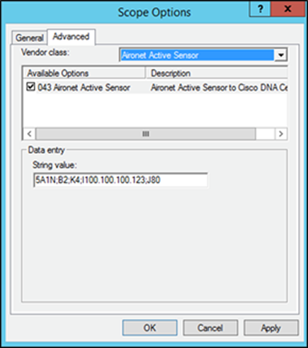
Specifying scope options for the sensor’s vendor class
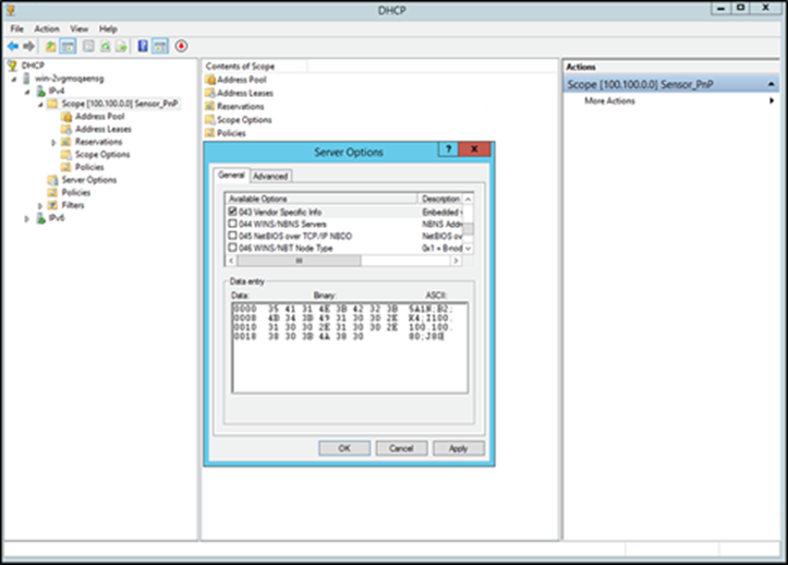
8. Within the Scope Options directory, and under the Option Name header, a custom option 43 field for the Aironet Active Sensor should appear. You’ve now completed configuring the conditional option 43 redirection using the device-side VCI string (Figure 38).
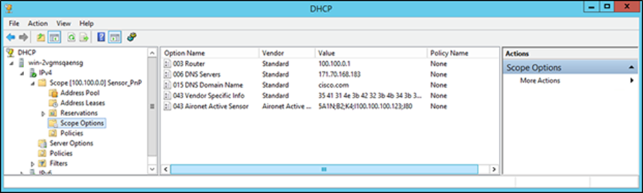
Verifying creation of the option 43 field
In addition to option 43, if the sensor has an 8.7.258 image, the sensor requires the Network Time Protocol (NTP) server IP address. The DHCP server includes the NTP server IP address in the option 42 field. This information is not required if the sensor software version is 8.8.261 or later, because the NTP server information is transferred as part of the sensor PnP provisioning process.
For information about DHCP options for PnP, see https://cs.co/dhcp_option_43.
Disclaimer: If your Cisco DNA Center (version 1.3.3.0 or above) is configured with only a domain name, and your Aironet Active Sensors are running an image earlier than 1.3.1.0, follow the steps below to ensure that the sensor’s PnP onboarding is successful.
● Create a DNS entry for “data.<FQDN>” (i.e., data.citisvs.cisco.com) and configure the resolution IP to be the same as the IP that the “dnac.<FQDN>” string within your PnP option 43 string (i.e., option 43 ASCII 5A1N;B2;K4;Idnac.citisvs.com;J80) would resolve to.
Note: The above is not applicable if your Cisco DNA Center certificate’s common name contains an IP address.
DNS-based Cisco DNA Center discovery
1. You can create a host record on the DNS server for the domain with the name PNPSERVER and the IP address of Cisco DNA Center (Figure 39).
● The sensor uses the DHCP received domain name to create a FQDN and make a pnpserver.domainname.com query to the DNS server for the Cisco DNA Center IP address.
● If Cisco DNA Center has a custom or certificate authority (CA) signed certificate, the certificate must contain the PnP FQDN string in the SAN DNS entries. Make sure Cisco DNA Center has a domain name configured, because if Cisco DNA Center is installed without a domain name, DNS-based discovery will fail.
Note: Make sure the IP DHCP pool has the dns-server (option 6) and the domain name (option 15) configuration.
For more information on DNS name-based discovery, visit https://cs.co/pnp-solution-guide.
Example:
ip dhcp pool vlan30
network 30.30.0.0 255.255.0.0
default-router 30.30.0.1
domain-name cisco.com
dns-server 100.100.100.11
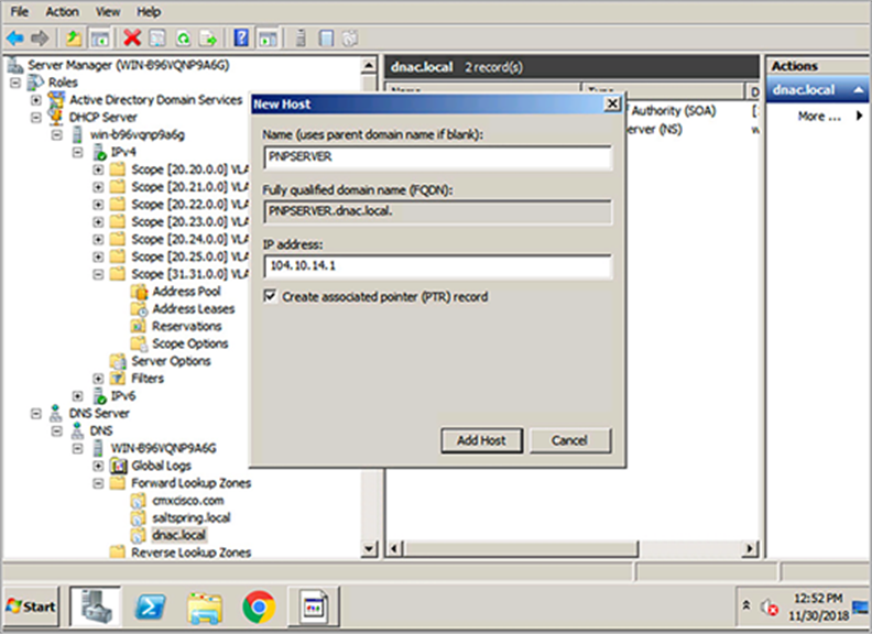
DNS configuration on Windows Server
How to deploy wired sensors inside your SD-Access Fabric:
1. Make sure that the option 43 is configured with the ip address of Cisco DNA Center ip address on the DHCP server.
2. Assign the sensor port to the right AP pool inside the port assignment inside the fabric.
3. Make sure that the sensor is able to get the right ip address in the AP pool with the right option 43, which is Cisco DNA Center ip address
4. After some time, you should be able to see the sensor shown up in the "Plug and Play" page inside the Cisco DNA Center
Cisco DNA provisioning through the CLI
Starting with Aironet Active Sensor Software Release 8.8.257.0, you can configure Cisco DNA Center manually through the sensor CLI.
1. Connect the sensor through the special console cable (AIR-CONSADPT=) (Figure 40).
2. Log in to the sensor with the default username and password (sensor/password).
3. Enter privileged mode by typing en, and then enter one of the following commands:
● Option 1: Cisco DNA Center with a certificate that includes the IP address
config dot11 pnp ip <Cisco DNA Center IP>
Example: config dot11 pnp ip 10.70.0.15
● Option 2: Cisco DNA Center with a certificate that includes only the FDQN
config dot11 pnp ip <Cisco DNA Center FQDN>
Example: config dot11 sensor pnp ip 100.100.100.80
config dot11 sensor pnp ip en-dnac.cisco.com <-- If DNAC use FQDN only certificate
Note: Using the different config command options with the Cisco DNA Center's IP or FDQN is contingent on Cisco DNA Center's certificate. If the certificate includes only the FQDN, you must use option 2; otherwise, the sensor will not join Cisco DNA Center properly.
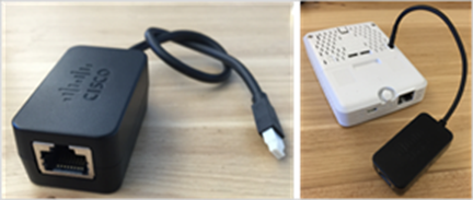
Sensor console connector
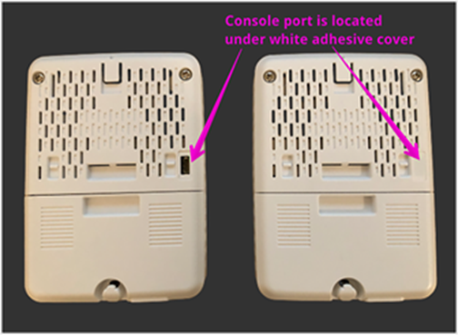
Location of console port in back of sensor
If the sensor is running Aironet Active Sensor Software Release 1.3.3 or later, day-0 SSH is available. Day-0 SSH offers remote SSH access to sensors, but it doesn’t allow privileged mode access.
The sensor’s console port is located under the white adhesive cover (Figure 41).
1. To provision the sensor to Cisco DNA Center manually using the CLI, log in with the following credentials:
◦ Sensor Version 2.1.2 and above: (sensor/password)
◦ Sensor Version 2.1.1 and below: (Cisco/Cisco)
2. Upon successful login, enter the following command:
config dot11 sensor pnp ip <Cisco_DNA_Center_IP_address>
Example: config dot11 sensor pnp ip 100.100.100.80
config dot11 sensor pnp ip en-dnac.cisco.com <-- If DNAC use FQDN only certificate This feature is useful when the sensor is deployed onsite without staging, or when it is reset to the factory default. The network administrator can find the sensor’s IP address by using the Cisco Discovery Protocol neighbor details, and SSH into the sensor and Cisco DNA Center IP address.
3. Similarly, to configure the NTP IP address, enter:
configure dot11 sensor ntp ip <NTP_server_ip_address>
Note: Typically, you don’t need to configure NTP, because the NTP IP address can be provided as part of the provisioning process, starting with the 8.8.261 image.
Connecting your sensor to the network
The sensor requires one logical interface, the special-purpose backhaul interface, which provides network connectivity between the sensor and Cisco DNA Center.
The sensor can use wired (using the PoE module) or wireless backhaul. For wireless backhaul, the administrator must choose one SSID from the existing WLAN setup. Keep in mind that backhaul SSID creation is not a part of Cisco DNA Automation. The administrator can choose any SSID that is created by Cisco DNA Center or manually created from the wireless controller.
The sensor uses backhaul to:
● Enable the keepalive heartbeat exchange between Cisco DNA Center and the sensor (HTTPS, heartbeat every minute)
● Download the new sensor test configuration
● Upload the sensor test result
● Update the sensor image
Note: The preceding sensor operations use HTTPS.
When the sensor uses wireless backhaul, it switches frequently between the test target SSID and the wireless backhaul SSID. For example, when the sensor finishes a series of tests from the configured AP in the 2.4-GHz band, the sensor switches the SSID to the backhaul SSID and reports the results to Cisco DNA Center.
After reporting is finished, the sensor reconnects to the test SSID and runs testing on the other band. Similarly, the sensor comes back regularly to Cisco DNA Center for a heartbeat. Ultimately, the sensor cycles through test SSID1 > backhaul SSID > test SSID2 > backhaul SSID > test SSID3 and time-slices wireless testing, reporting, and heartbeat verification.
1. Due to the unique behavior described above, we recommend that you enable Fast SSID change from the wireless settings (Figure 42).
● The Fast SSID change option does not impact sensor test results or sensor operation.
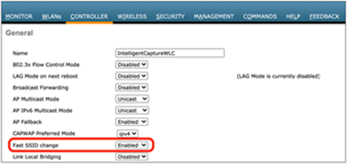
Location of the Fast SSID change toggle in the AireOS WLC GUI
Note: For the Cisco Catalyst 9800 Series controllers, Fast SSID change is enabled by default.
Persistent wireless backhaul
If the sensor is running Software Release 1.3.3 or later, it supports persistent wireless backhaul, which is a dedicated wireless connection from the sensor to Cisco DNA Center. As long as the sensor’s test band remains in a single band, persistent wireless backhaul is maintained. When the wireless test band changes, the wireless backhaul connection shifts to the other band.
During a wireless backhaul connection, the sensor uses virtual MAC addresses both for the wireless persistent backhaul to connect with Cisco DNA Center and for connection to test an AP’s wireless network (Table 3). Figure 43 describes the advantages of persistent wireless backhaul.
Table 3. Backhaul type to sensor MAC address matrix
| Connection type |
Sensor virtual MAC syntax |
| Persistent wireless backhaul |
Base radio MAC + 0x10 |
| Connection to AP’s SSID for testing |
Base radio MAC + 0x11 |
Example: If the sensor’s radio MAC is AB:CD:EF:00:00:00, the MAC address used for the persistent wireless backhaul will be AB:CD:EF:00:00:10, and the MAC address used to connect to an AP’s radio for testing will be AB:CD:EF:00:00:11.
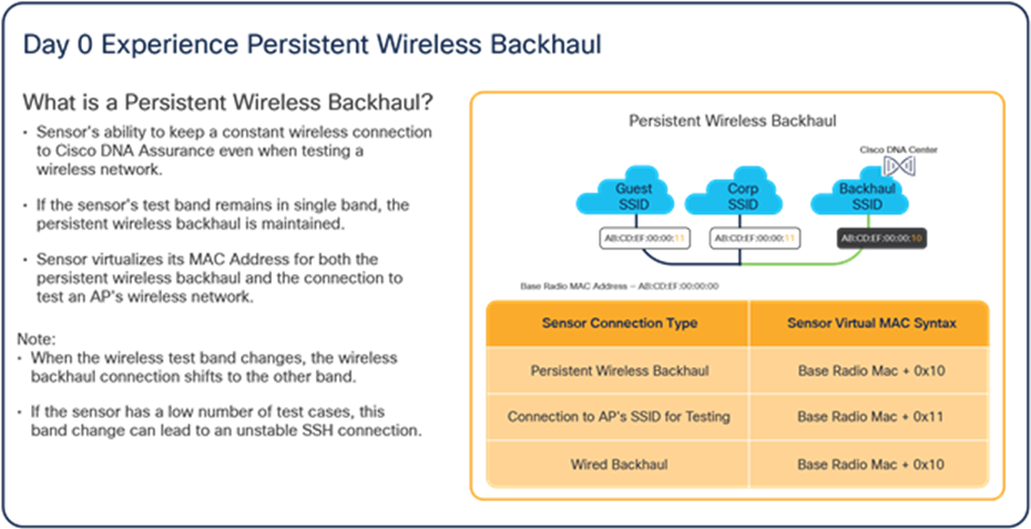
Advantages of persistent wireless backhaul
Creating a sensor backhaul profile in Cisco DNA Center
A sensor backhaul profile is essential to claiming the sensor on the PnP page. The PnP Claim page has a default sensor backhaul profile titled CiscoSensorProvisioning. This default profile has the settings for an open wired backhaul and the CiscoSensorProvisioning SSID as a wireless backhaul.
For sensor software version 1.3.3.x or lower, create a custom wireless backhaul to connect to the DNAC Server with the steps in the disclaimer following Figure 58.
For sensor software version 1.3.3.x to 2.1.2, you have can utilize the default backhaul profile.
For sensor software version 2.1.2 or higher, you have the option to utilize the default backhaul profile for both wired and wireless backhaul but now also have the option to configure a non-open wired backhaul like in Figure 45 below. After DNA Center version 2.1.2, it is mandatory to have both the wired and wireless backhaul section of the backhaul settings to be filled.
Wired backhaul: If your sensor discovered Cisco DNA Center through a wired backhaul, you can create a custom backhaul profile if you would like to configure an 802.1X EAP security communication method on the wired side. Wired backhaul is prioritized over Wireless Backhaul.
Note: Custom wired backhaul is supported starting with Cisco DNA Center Release 2.1.2.
Wireless backhaul: If your sensor discovered Cisco DNA Center through a wireless backhaul, you can create a custom backhaul profile if you want your sensor to communicate with Cisco DNA Center through an SSID other than the default CiscoSensorProvisioning SSID.
Note: Wireless backhaul for Fabric is not supported in Fabric mode.
1. To create a new sensor backhaul configuration, open the menu and click Assurance > Manage > Sensors, then Setting > Backhaul Settings, then Add Backhaul (Figure 44).
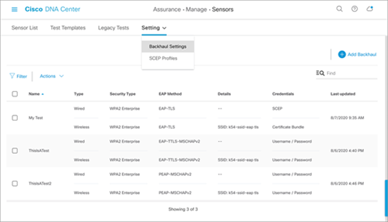
Location of backhaul settings and Add Backhaul button in Cisco DNA Center
Note: The setting is local to Cisco DNA Center and is not pushed to the wireless controller.
2. Wired backhaul: Leave Level of Security as the default value of Open, or select the 802.1X EAP option to select a security type (Figure 45).
1. 802.1X EAP security options: EAP-FAST, PEAP-MSCHAPv2, EAP-TLS, PEAP-TLS, EAP-TTLS-MSCHAPv2, EAP-TTLS-PAP, EAP-TTLS-CHAP, EAP-FAST-GTC, EAP-PEAP-GTC (Figure 45).
2. If EAP-FAST, PEAP-MSCHAPv2, EAP-TTLS-MSCHAPv2, EAP-TTLS-PAP, EAP-TTLS-CHAP, EAP-FAST-GTC, or EAP-PEAP-GTC is selected, enter a username and password (Figure 46).
3. If EAP-TLS or PEAP-TLS is selected, either upload a certificate bundle into Cisco DNA Center, along with the bundle’s username and password, or enroll using SCEP (refer to the “Certificate Management with SCEP” section for more information) (Figure 47).
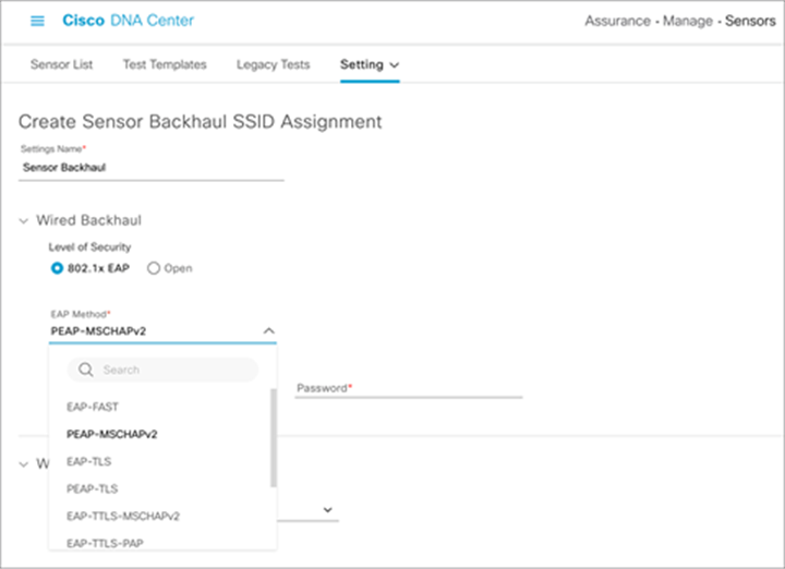
Configuring a wired backhaul profile
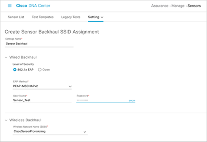
Configuring username and password with PEAP-MSCHAPv2 for wired backhaul profile
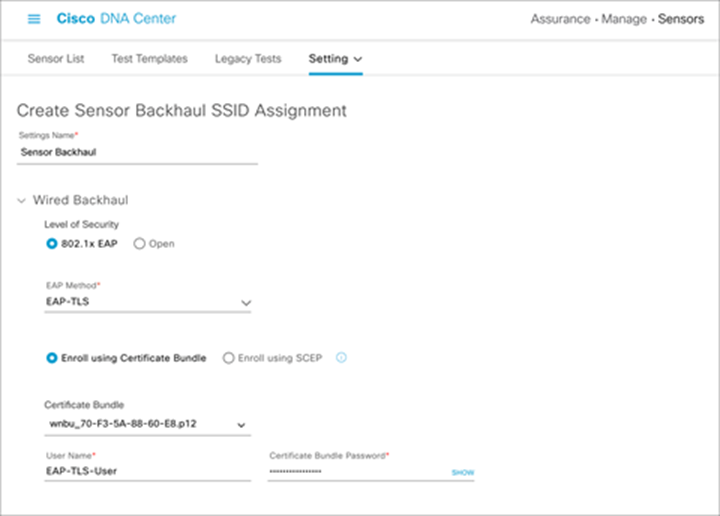
Configuring a custom certificate, username, and password with EAP-TLS for wired backhaul profile
3. Wireless backhaul: Select an SSID from the drop-down menu and ensure that the selected SSID matches an SSID that is being broadcast within the proximity of the sensors being claimed with this profile. (Figure 48).
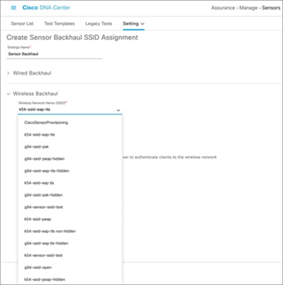
Configuring a wireless backhaul profile and selecting an SSID
a. Configure the security credentials of the chosen SSID (Figure 49).
b. Wireless security options:
● WPA2-Enterprise (EAP-FAST, PEAP-MSCHAPv2, EAP-TLS, PEAP-TLS, EAP-TTLS-MSCHAPv2, EAP-TTLS-PAP, EAP-TTLS-CHAP, EAP-FAST-GTC, EAP-PEAP-GTC) (The authentication methods in bold are newly introduced in Cisco DNA Center 2.1.2.)
● WPA2-PSK
● Open
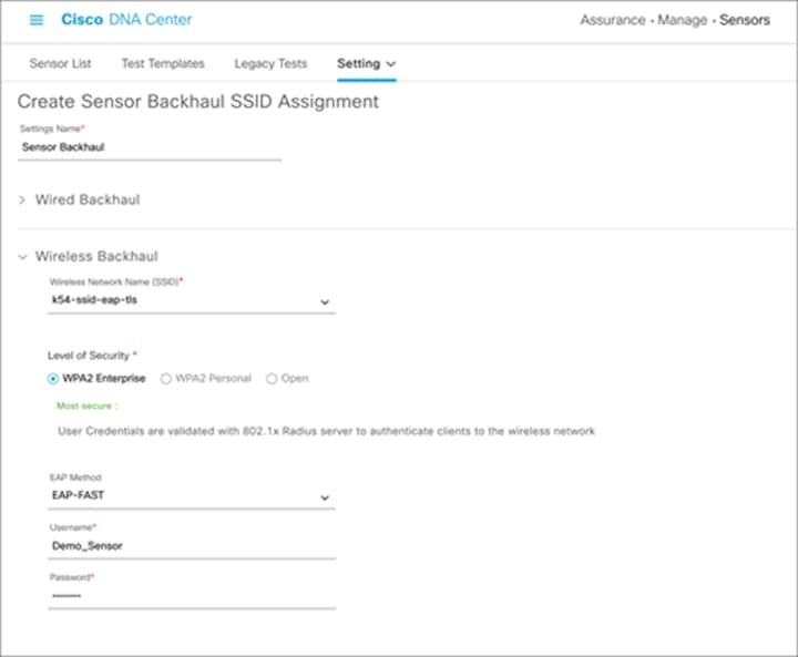
Configuring username and password with EAP-FAST wireless backhaul profile
Note:
● We recommend that you use the latest Aironet Active Sensor Software Release 2.1.2.0 for wireless backhaul operation.
● If you are running DNA Center version 2.1.2, to bypass the requirement for having both a wired and wireless backhauls configured in the backhaul profile, either use the default CiscoSensorProvisioning SSID, or select any ssid in your network and provide invalid credentials.
● If the sensor is assigned an SSID that is different from the CiscoSensorProvisioning SSID, the sensor does not use the CiscoSensorProvisioning SSID after PnP provisioning, because it’s configured with a new backhaul SSID. If the backhaul SSID fails to connect, the sensor falls back to the CiscoSensorProvisioning SSID.
● If you’re using an open security wired backhaul profile, select the default CiscoSensorProvisioning backhaul profile because Cisco DNA Center will not allow you to create an open security wired backhaul together with anything but an open security wireless backhaul profile.
Provisioning: How to claim the sensor
1. Option 1 – PoE module: If your sensor has a PoE module, connect your sensor to the PoE port on the switch.
Option 2 – Wireless backhaul connection: If your sensor uses a wireless backhaul connection, power the sensor by plugging it into a wall power socket or use the adapter and attached micro USB Type B connector.
Note: For either backhaul type, ensure that the sensor has HTTP (TCP 80) and HTTPS (TCP 443) reachability to the Cisco DNA Center server.
2. After the sensor is powered on, wait for approximately 5 minutes. If the sensor can reach the Cisco DNA Center server, the sensor appears in an unclaimed state within the PnP page. You can navigate there by opening the hamburger menu and then clicking Provision > Plug and Play.
3. Before claiming the sensor, you can change the default sensor name to the desired name. To change the sensor name, open the hamburger menu and click Provision > Plug and Play. Then select the target sensor and choose Actions > Edit (Figure 50).
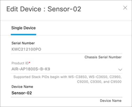
Edit Sensor menu
Note:
● In previous Cisco DNA Center Software Releases, 1.3 and earlier, users have the ability to change the sensor name only at this stage and not after the claim process, unless the device is deleted from the inventory.
● Beginning with Cisco DNA Center Software Release 2.1.2, the user has the flexibility to change the name whenever desired.
4. After you change the sensor name, your sensor is ready to be provisioned. Select the sensor from the list of unclaimed devices and click Claim in the Actions drop-down menu (Figure 51).
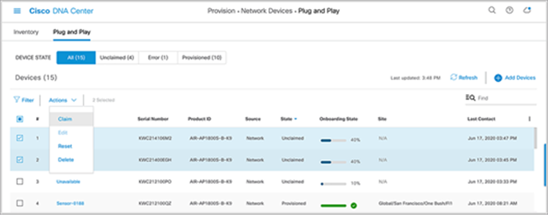
Location of the Claim option
5. Select a site to claim the sensor (Figure 52).
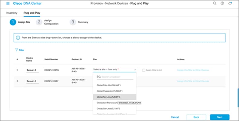
Selecting a location to claim the sensor
6. Wireless backhaul: If you didn’t create a sensor PnP profile, you can use the default CiscoSensorProvisioning sensor profile, which is automatically selected (Figure 53).
Wired backhaul: If you are deploying a wired sensor, you must still choose one profile, in which case the default profile is a convenient option (Figure 53).
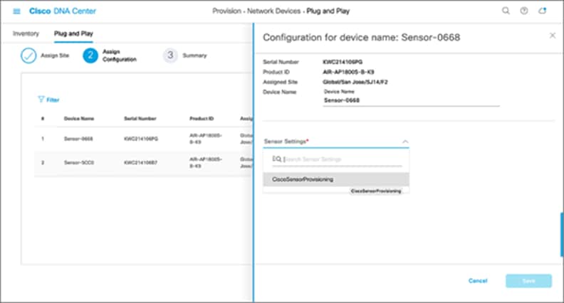
Selecting the sensor profile for a claimed sensor
7. If you want to change the sensor name after the PnP claim, go to Assurance > Manage > Sensors, and choose Edit Sensor Name(s) from the Actions drop-down menu (Figure 54).
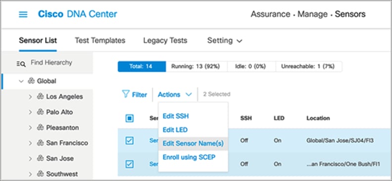
Editing the sensor name
8. Ensure that the device status changes from Unclaimed to Planned to Onboarding to Provisioned (Figure 55).
● The device remains in the Provisioned state unless it is fails to be provisioned. In this case, the sensor changes to an error state. Any errored entries remain even if the device is removed from the network.
● When the sensor is in the Managed state, it’s ready to download the sensor-driven test configuration and run the sensor test.
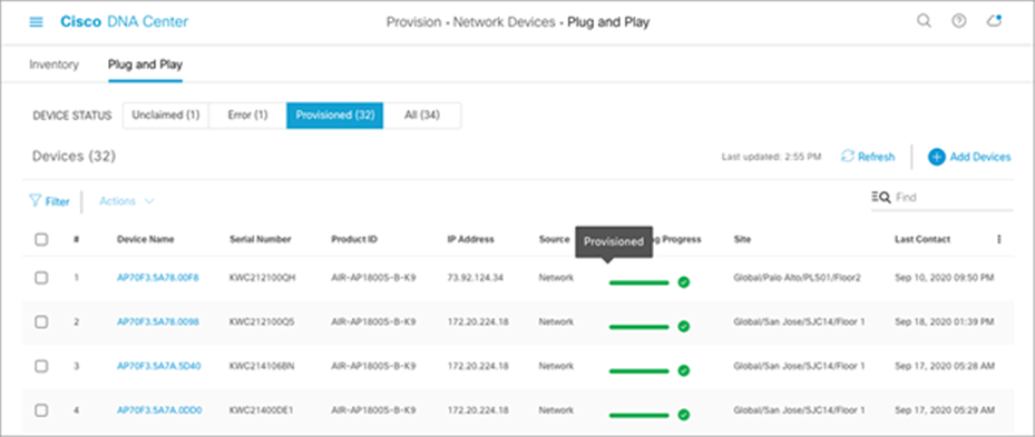
Sensor provisioning – sensors in provisioned state after claiming
● If the sensor changes to an error status, you can view the error details under the History tab. You can always delete a sensor with an error status; that sensor then returns to the list in an unclaimed state (Figure 56).
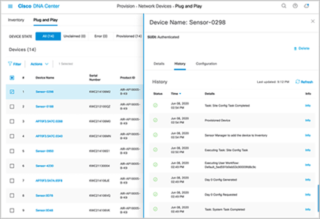
Viewing the history of a sensor
Disclaimer: If your sensor is running version 8.8.259.0, it supports using the CiscoSensorProvisioning SSID only as a means to contact Cisco DNA Center through Plug and Play, but not as a wireless backhaul method for continued management. To onboard your sensor using a wireless backhaul method, the network admin needs to upgrade the sensor software from 8.8.259.0 to 1.3.3.0 or a later release. Follow the steps below to claim your 8.8.259.0 sensor to Cisco DNA Center properly.
5. Create a custom wireless backhaul profile.
6. Claim the sensor from the PnP page to the custom wireless backhaul profile created.
● The SSID in this backhaul profile must match a WLAN that’s being broadcast near your sensor.
If you’d like your sensors to use the CiscoSensorProvisioning SSID as the wireless backhaul, continue with the following steps:
1. Upgrade the sensor to Release 1.3.3.0 or above through the image repository page described in “Upgrade the Sensor Software” below.
2. Delete your claimed sensor from inventory, and it will show up on the Plug and Play page as unclaimed again.
3. Claim the sensor again, but this time to the CiscoSensorProvisioning backhaul profile.
Description: After the sensor has been provisioned, one method of upgrading the sensor software is via the CLI built into the sensor and accessible via SSH or console cable.
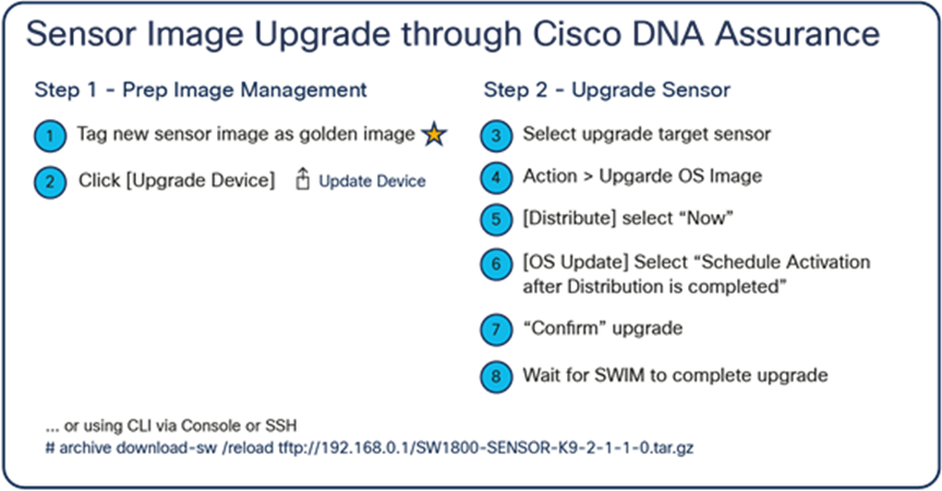
● Once the sensor’s CLI has been accessed, a software upgrade can be performed on the sensor by running the following command:
archive-download-sw /force-reload /overwrite tftp://<ip address>/image
Steps to upgrade the sensor through Cisco DNA Center
After you provision the sensor, you can update the sensor software to the latest release using Cisco DNA Center. Currently, Aironet Active Sensor Software Release 2.1.2.0 is the latest, and it aligns with the latest Cisco DNA Center Software Release 2.1.2.0. After you enter your Cisco.com ID and password into Cisco DNA Center, Cisco DNA Assurance automatically retrieves the list of device images from Cisco.com.
1. Option 1 – Cisco.com image import: Before upgrading the image, mark the new image within the Image Repository page (viewed by clicking Design > Image Repository within the hamburger menu) as a golden image so that it will be used as the new sensor software. You mark the new sensor software as the golden image by clicking the star icon next to the desired image in the list (Figure 55).
● Cisco DNA Center starts to retrieve the new software from Cisco.com.
Option 2 – Manual import: Alternatively, you can manually import the sensor software into Cisco DNA Center from your local browser. Import the sensor software from the Image Repository tool by clicking Design > Image Repository within the hamburger menu and then clicking Import (Figure 58).
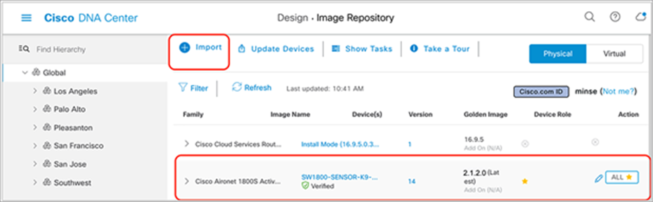
Marking an image as a golden image
2. After preparing the golden image, you can start the image upgrade from the Inventory page. The first step is to select the target sensors to be upgraded.
3. After you select all the sensors, click Action and select Image Upgrade. Make sure all selected sensors are in Managed status (Figure 59).
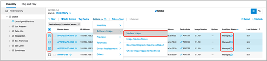
Starting the image upgrade
4. Click Now and then Next (alternatively, click Later to schedule the upgrade for a later time) (Figure 57).
5. Check the Schedule Activation After Distribution Is Completed check box (Figure 60).
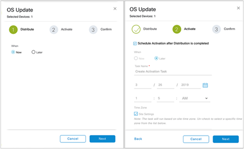
Scheduling an image upgrade
6. Click Confirm to initiate the image upgrade.
There are several conditions under which the sensor image upgrade can fail:
● Failure condition 1 – The golden image has not been selected: After you confirm the upgrade target image on the Image Repository page, you need to manually click the star icon next to the image version to determine the upgrade target image (Figure 61).

Golden image selected for upgrade
● Failure condition 2 – Partial collection failure status: This status means that the sensor failed to exchange heartbeats with Cisco DNA Center. In this case, the image upgrade is not initiated. Only after all of the selected sensors are ready to be upgraded can you select Now to start the upgrade of all selected sensors.
● Failure condition 3 – Failure conditions 1 and 2 occur in a selected group: When multiple sensors are selected as upgrade targets and any of the selected sensors experience failure condition 1 or 2, the image upgrade is not initiated.
Placing sensors on the floor map
You can also provision sensors from the floor map in the Design section.
1. Open the hamburger menu and click Design > Network Hierarchy, then click the desired floor and click Edit (Figure 62).
2. You can drag and drop sensors from the upper right corner of the map to their current placement and click Save to apply the changes to the map (Figure 62).
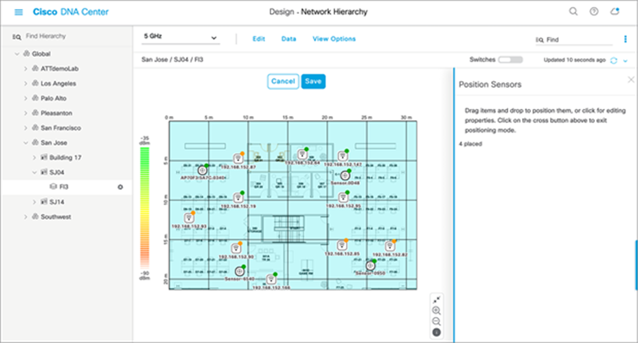
Placing sensors on the floor map
Description: The Sensor List page allows you to view and configure everything regarding the Aironet Active Sensor.
This page allows you to configure various settings such as Sensor Name, SSH Username and Password, and LED, as well as to view a sensor’s current operational status (Running, Idle, or Unreachable) and many other attributes (Figure 63).
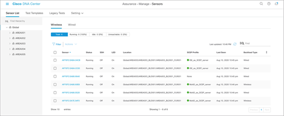
Sensor List page
Note:
● A sensor uses a single admin ID between SSH and CLI, so if you change the username and password of a sensor, both the SSH and CLI login credentials are changed.
● The default sensor username and password are Cisco/Cisco before Release 2.1.2 and sensor/password starting with Release 2.1.2. When you configure a username and password, this default value is overwritten.
● The Sensor List page is available only in Cisco DNA Center Software Release 1.3.1 and later.
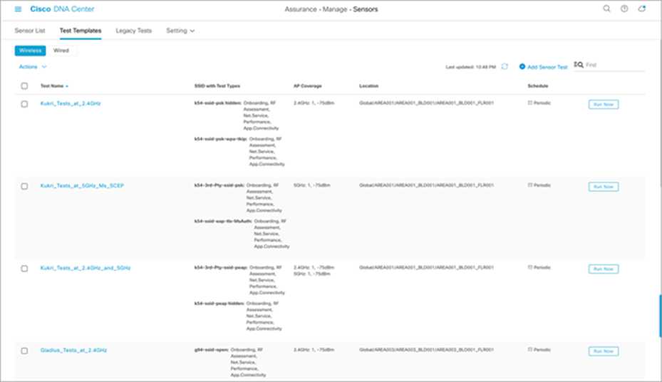
Creating a sensor test template configures the types of wireless tests to run, the frequency with which to run them, and the APs that the tests are targeted to.
1. To create a test suite, from the hamburger menu choose Assurance > Manage > Sensors, and then click Test Templates and Add Sensor Test (Figure 64).
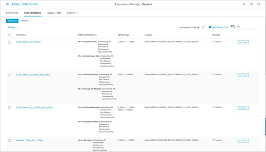
Creating a new sensor test
Note: The previous sensor-driven tests are renamed to the legacy test suite in Cisco DNA Center.
Comparing new to legacy sensor test templates
● The template can now be assigned to multiple floors and sites. You no longer need to create a sensor test for every floor.
● The template allows a unique sensor test configuration to be assigned to each SSID. Previously, all configured SSIDs had to share the same test configuration.
● The sensor coverage threshold is now configurable per band (2.4 or 5 GHz).
● The Run Now option has been added to provide the ability to start the test immediately.
● The sensor test interval has been expanded from 7 minutes to 24 hours.
● The sensor test can now be enabled by time of day and day of week.
● A new sensor test interval called Continuous has been added and allows the sensor to run continuously without stopping.
◦ Disclaimer: Do not use the Continuous test interval for performance testing, as it may overload your AP.
● A single sensor can use only a single sensor test template, so you know exactly what test is running per sensor or per location.
● Certain sensor tests can take longer, and the total sensor test duration varies depending on the number of selected sensor test types. The minimum sensor test interval is automatically adjusted based on the estimated sensor test duration.
● Support for HTTPS and iPerf3 tests has been added.
● You can configure templates using a new UI workflow.
● Sensor tests can easily be duplicated, edited, deployed, and undeployed.
Onboarding
● Association, authentication, DHCP
◦ Description: The sensor attempts to join the user-defined wireless network.
◦ Pass criteria: The sensor can join the wireless network and receive an IP address.
RF assessment
● Data rate, signal-to-noise ratio (SNR)
◦ Description: The sensor attempts to collect data rates and SNR data from non-onboarding tests.
◦ Pass criteria: The sensor can collect data rates and SNR data from non-onboarding tests.
◦ Note: RF assessment tests are not run unless additional non-onboarding tests, such as DNS, RADIUS, and so on, are configured.
Network services tests
● DNS
◦ Description: The sensor attempts to resolve the user-defined hostname through the network's DNS server.
◦ Pass criteria: The sensor can reach the network's DNS server and resolve the hostname.
● RADIUS – Authenticating client (part 1)
◦ Prerequisite: Create a user identity entry within the network's RADIUS server, which includes a user-defined username and password.
◦ Description: The sensor acts as a client and attempts to authenticate into the 802.1X enterprise security network using the user-defined username and password.
◦ Pass criteria: The sensor can authenticate itself into the wireless network as a client.
● RADIUS – Client authenticator (part 2)
◦ Prerequisite: Create a client authenticator entry within the network's RADIUS server, which includes the sensor's IP address and a user-defined shared secret.
◦ Description: The sensor acts as the client authenticator and attempts to connect to the network's RADIUS server using the user-defined shared secret, port number, and protocol (PAP or CHAP).
◦ Pass criteria: The sensor can establish communication with the RADIUS server as a client authenticator.
◦ Note: If only the active user directory is used to authenticate, only PAP is supported.
Performance tests
● Internet (NDT)
◦ Description: The sensor attempts to run a performance test to the nearest public or user-defined private MLAB server to obtain downlink and uplink throughput data as well as latency through port 3001.
◦ Pass criteria: The sensor can reach the MLAB server and collect throughput, latency, and packet loss data.
● iPerf3
◦ Description: The sensor attempts to run a performance test to the user-defined private iPerf3 server.
◦ Pass criteria: The sensor can reach the iPerf3 server and collect throughput, latency, and packet loss data.
● IP SLA
◦ Description: The sensor attempts to send a UDP probe to the wireless network using the user-defined traffic service level (Platinum, Gold, Silver, Bronze) and functions as the responder to determine the jitter, latency, packet loss, and round-trip time of the last hop.
◦ Pass criteria: The sensor can reach the wireless network and collect latency, packet loss, jitter, and round-trip time data.
◦ Note: IP SLA testing is not supported in the following conditions:
◦ The Cisco wireless infrastructure is running Cisco AireOS Release 8.5.
◦ P2P blocking is enabled on your WLAN.
◦ Cisco IOS Wave 1 APs are being used.
Application tests
● Host reachability
◦ Description: The sensor attempts to reach the user-defined IP address through ping.
◦ Pass criteria: The sensor can reach the user-defined IP address through ping.
● Web
◦ Description: The sensor attempts to resolve the user-defined URL through the network's DNS server, and then tries to reach the resolution IP address through ports 80 (HTTP) or 443 (HTTPS).
◦ Pass criteria: The sensor can reach the network's DNS server, resolve the hostname, reach the resolution IP address, and collect latency and response time data.
● FTP
◦ Description: The sensor attempts to log in to a user-defined FTP server.
◦ If you choose the Upload option, the sensor uploads the text file to the user-defined path.
◦ If you choose the Download option, the sensor downloads the file from the user-defined file path.
◦ Pass criteria: The sensor can reach the FTP server and either upload or download the file successfully.
Email tests
● POP3
◦ Description: The sensor attempts to reach the user-defined POP3 server through port 110.
◦ Pass criteria: The sensor can reach the POP3 server through port 110.
● IMAP
◦ Description: The sensor attempts to reach the user-defined IMAP server through port 143.
◦ Pass criteria: The sensor can reach the IMAP server through port 143.
● Outlook Web Access
◦ Description: The sensor attempts to log in and log out of the user-defined Outlook Web Access server (Example: https://owa.example.com).
◦ Pass criteria: The sensor can log in and log out of the Outlook Web Access server.
Creating a test template
1. To create the test suite, open the hamburger menu and click Assurance > Manage > Sensors, then Test Templates, then Add Sensor Test (Figure 65).
Set Up Sensor Test page
2. Enter a template name and choose Cisco SSIDs from the prepopulated list on the left, or add third-party SSIDs and select the corresponding level of security (Figure 66).
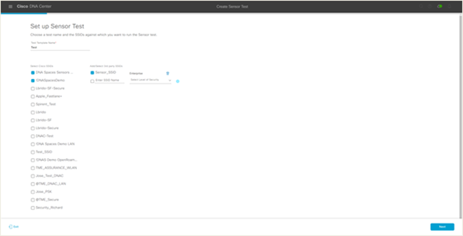
Choosing SSIDs for the sensor test
This ability for a sensor to associate with any third-party SSID creates a large number of advantages:
● Users can assess the health of any legacy network or even a third-party network.
● Users are no longer required to register their AP to a WLC in Cisco DNA Center.
● Limitations: If a third-party SSID is used, you will be unable to run certain tests such as IP SLA, select specific APs for the sensors to target, or view data on the Sensor 360 page’s Neighbor Map view.
Note: Third-party SSID support is available only in Cisco DNA Center Software Release 2.1.2 and later.
3. After you choose the test target SSID, enter the credentials for sensor wireless onboarding. The available options for entering SSID credentials are Open (no credentials), ISE Guest Portal, or ClearPass Guest Portal (Figure 67).
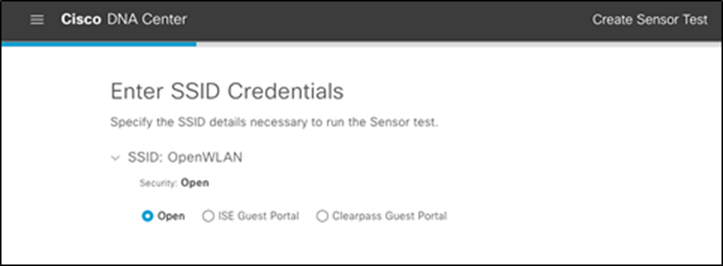
Options provided when creating a new SSID during sensor test creation
4. If ISE Guest Portal is selected, choose the labels that correspond to those in your ISE guest portal (Figure 68).
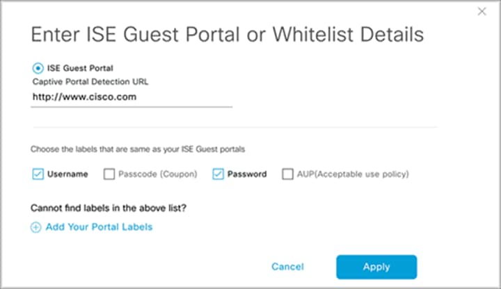
Configuring ISE guest portal details during test creation
If ClearPass Guest Portal is selected, choose the labels that correspond to those of your ISE guest portal (Figure 69).
Enter ClearPass guest portal credentials and a WLC virtual IP address (Figure 69).
Note: Configuring a ClearPass guest portal enables external web authentication testing using Aruba’s ClearPass server.
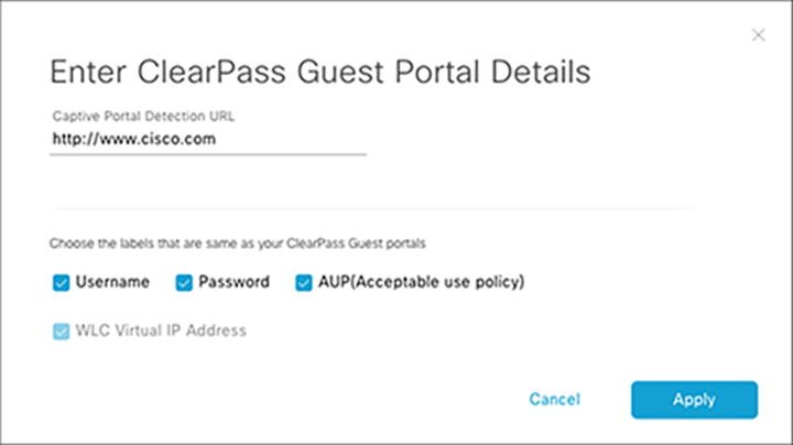
Configuring ClearPass guest portal details during test creation
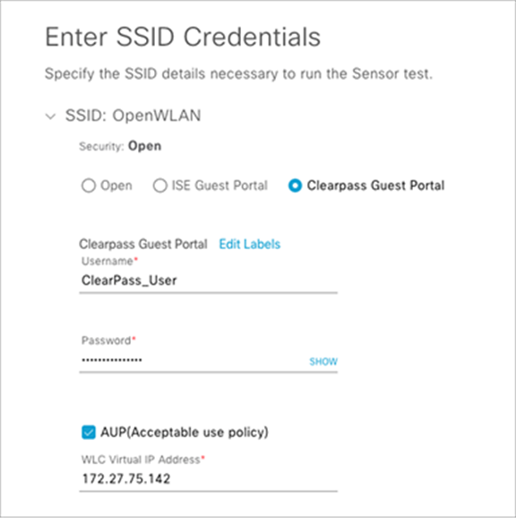
Configuring ClearPass guest portal credentials and WLC virtual IP address during test creation
5. Select the types of sensor tests that you would like to be part of this test template (Figure 71).
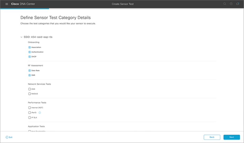
Choosing types of sensor tests
6. Check the box next to Internet (NDT) to configure that test as part of the test template (Figure 72).
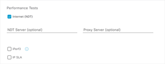
Performance Tests – Internet (NDT)
Note: The Internet test uses the distributed NDT from the mLab server in the cloud (Figure 73).
Leaving the NDT Server field blank
If you leave the NDT Server IP address field empty, the sensor sends an HTTP query to the mLab server (https://mlab-ns.appspot.com/ndt?format=json) to get the nearest mLab server information, as follows:
{
“city”: “San Francisco Bay Area_CA”,
“url”: “http://ndt.iupui.mlab2.nuq07.measurement-lab.org:7123”,
“ip”: [
“209.170.110.216”,
“2001:2030:0:12::216”
],
“fqdn”: “ndt.iupui.mlab2.nuq07.measurement-lab.org”,
“site”: “nuq07”,
“country”: “US”
}
The sensor then uses the returned NDT server cluster information to run actual performance testing. It uses TCP port 3001 for performance testing.
Adding an NDT server IP
If the connection to the Internet requires a proxy server, you can add one.
The proxy server address needs to be an IPv4 address, because the FQDN format is not yet supported.
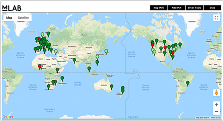
mLab server UI
Note:
● Typically, the private NDT server is not available, so the NDT Server IP address field can be left blank; however, if desired, the source code to set it up can be found at https://github.com/m-lab/ndt-server.
● The mLab server provides the NDT server information, so you don’t need to prepare the server.
● As a best practice, we recommend dedicating a single sensor per build or site for such a test.
● The recommended NDT test cycle is once every 6 hours per floor.
7. Check the box next to iPerf3 to configure that test as part of the test template (Figure 74).
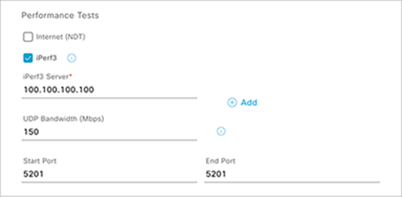
Performance Tests – iPerf3
Description:
● The iPerf3 test was introduced in Cisco DNA Center Software Release 2.1.1 and enables you to conduct a sensor speed performance test by pumping traffic to a private iPerf3 server.
● You can add up to five iPerf3 servers and test up to five separate ports per server consecutively, allowing a sensor to test up to 25 iPerf3 server instances during a single test cycle. These tests will be executed with a round robin method.
● The recommended iPerf3 test cycle is once every 6 hours per floor.
8. Check the box next to IP SLA and select a QoS condition to configure that as part of the test template (Figure 75).
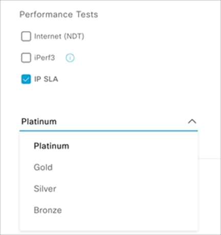
Performance Tests – IP SLA
Description:
● In IP SLA testing, the sensor measures IP SLA performance using a UDP echo/jitter probe against a connected AP.
● When the sensor sends IP SLA traffic, the AP terminates the IP SLA traffic at the first hop, regardless of whether or not the AP is in traffic forwarding mode (local, Flex, or fabric).
● IP SLA traffic can choose different Wi-Fi Multimedia (WMM) User Priority (UP) tagging values to simulate wireless performance in various quality-of-service (QoS) conditions.
Table 4 depicts the WMM UP and Differentiated Services Code Point (DSCP) values associated with each selectable service level in the IP SLA performance test.
Table 4. WMM UP and DSCP values for QoS conditions in the IP SLA test
| Service level |
WMM UP |
DSCP |
| Platinum |
6 |
46 (EF) |
| Gold |
5 |
34 (AF41) |
| Silver |
2 |
18 (AF21) |
| Bronze |
1 |
10 (AF11) |
The test target SSID QoS level should be higher than the QoS value configured for the sensor IP SLA. For example, if the SSID QoS setting is Gold and the sensor IP SLA QoS setting is Platinum, the AP cannot prioritize Platinum.
Note:
● IP SLA testing is supported on Wave 2 (Aironet 1800, 2800, 3800, and 4800 Series) and Wi-Fi 6 (Cisco Catalyst 9100) APs running AireOS Release 8.8.111.0 and later and Catalyst 16.12.1s and later.
● Only in Cisco DNA Center Software Release 2.1.2 and later can a destination target server be specified for sensor performance tests.
9. Check the box next to RADIUS and complete the various fields to configure that as part of the test template (Figure 76).
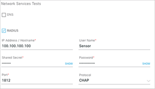
Network Services Tests – RADIUS test
Description: In the RADIUS test, the sensor acts as a RADIUS authenticator and authenticates through a wireless device. The sensor can test the RADIUS server using PAP or CHAP.
Note: If you have a Wi-Fi onboarding test that includes 802.1X/EAP authentication, this RADIUS test is already covered as part of the onboarding test.
10. Check the box next to Web and enter a URL to configure that as part of the test template (Figure 77).
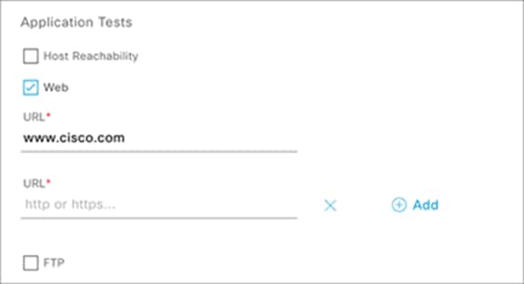
Application Tests – Web test
Description: The application tests measure serviceability and time to connect to a specific application. This can include either HTTP or HTTPS URLs.
11. Check the box next to FTP and enter the various FTP credentials to configure that as part of the test template (Figure 78).
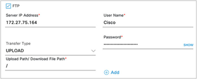
File transfer tests
Description: The file transfer tests will upload a file to or download a file from the specified FTP server.
Note:
● Outlook Web Access supports only Exchange Server and not Office 365.
● The web test supports HTTP and HTTPS. You can use a FQDN as the URL.
● The name of the internal file that gets uploaded in an upload test is FTP_ UPLOAD_FILE_[Sensor MAC Address].txt. When you choose Download or Upload or Download, choose a file that is smaller than 5 MB.
● Multiple FTP servers can be added as part of a single test template by clicking the Add button (Figure 79).
12. Check the box next to POP3, IMAP, or Outlook Web Access and fill in the various server names and credentials to configure that as part of the test template (Figure 79).
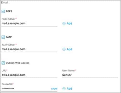
Email test
Description: The email test verifies the connection to an IMAP server over TCP port 143, a POP3 server over TCP port 110, or an Outlook Web Server by logging into the OWS (with on-premises Exchange server) and verifying access.
Note: Multiple email servers can be added as part of a single test template by clicking the Add button (Figure 77).
13. At this point, you should have completed selecting the tests you want to be part of this template. Click Next.
14. From the Select AP Coverage page, configure which band to test, the RSSI coverage threshold, and the number of test target APs per band (Figure 80).
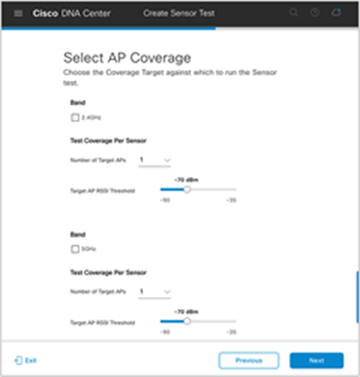
Configuring the number of APs and RSSI range for sensors to target
Note: The Target AP RSSI Threshold slider bar is inverted. In the example shown in Figure 80, the sensor would be configured to target APs in an RSSI range of -70 to -35 dBm.
15. Click Next (Figure 79) to display the Summary page (Figure 81).
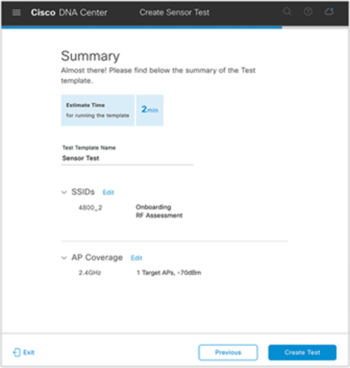
Summary page to review the sensor tests configured
Description:
● The Summary page shows a recap of the configured sensor test options and allows you to review or go back to edit each section.
● Cisco DNA Center will calculate the estimated time required to run through the entirety of the tests once. The estimated test time is used to determine the sensor test interval.
16. Click Create Test (Figure 81) to complete the sensor test creation process (Figure 82).
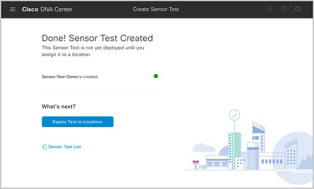
Sensor test creation confirmation screen
17. After you create the sensor test template, you can deploy a sensor test by clicking Deploy Test to Locations (Figure 82), or you can navigate directly to the Test Templates page (Figure 83).
18. Click Deploy Test next to a test template you would like to deploy to a site (Figure 83).
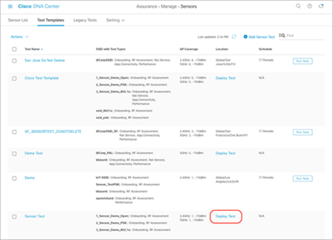
List of sensor tests created
19. From the sites hierarchy on the left, select the site(s) to deploy your test template to (Figure 84).
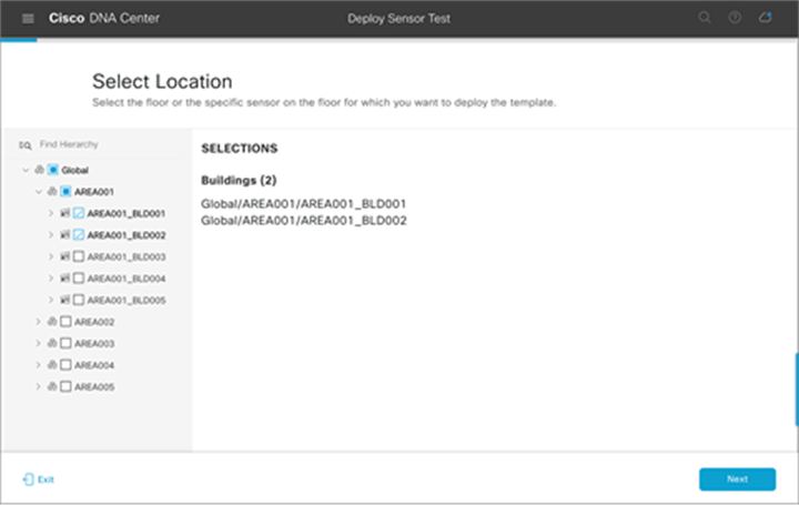
Selecting buildings or areas when deploying test templates
20. Optional – Select individual sensors: If you would like to specify individual sensors to run the selected test, select the floor and you will be given an option to click the All Sensors button, which will allow you to select which sensors to deploy this test to (Figure 85).
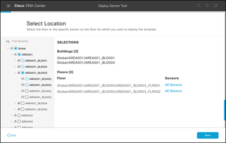
Selecting individual floors when deploying test templates
21. Optional – Select target APs: Expand the Target AP # column in each row to reveal the APs assigned to the same floor as each of the sensors. Selecting the check box next to the AP under each sensor will allow you to specify which AP each sensor will target during the test cycle. If none is selected, the sensor will test the number of APs configured within the test template using the RSSI threshold (Figure 86).
Note: If more target APs are selected than what was configured within the test template, the number configured within the test template will be overridden. There is no hard maximum number of APs a single sensor can test per test cycle.
22. Click Save and then Next to continue the workflow process (Figure 86).
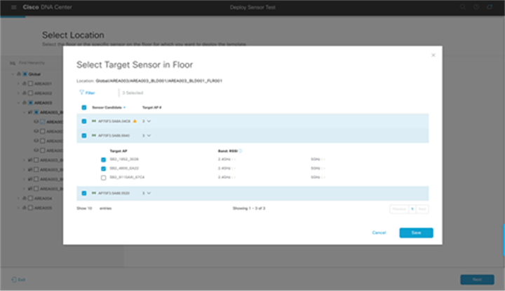
Selecting individual sensors to deploy the test on
Note:
● Each sensor can be assigned only one sensor test template; therefore, a warning that the test will be overwritten will be displayed in the form of a yellow triangle if there is already a template deployed to the selected sensors.
● Starting with Cisco DNA Center Software Release 1.3.3, using an AP as a sensor is no longer supported, so APs are not selectable as sensor candidates.
23. Select a sensor test interval to determine the frequency with which the sensor runs the test, then click Next (Figure 87).
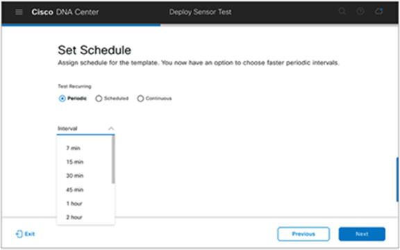
Configuring the schedule for the sensor test
Description: This page enables you to specify how often the sensor test will run: periodically, on a specified schedule, or continuously.
● Periodically: This option allows you to select a frequency by time (between 7 minutes and 24 hours) with which the sensor will run the assigned test.
Example: If you select 7 minutes, the sensor will run the test once every 7 minutes.
Note: The sensor test repeat interval must always be higher than the estimated test cycle. If the sensor test estimated time is 25 minutes, the minimum repeat interval is 30 minutes, and so the 7 min and 15 min options are disabled in the drop-down list.
● Scheduled: This option allows you to select a specific day of the week and time at which the sensor will run the assigned test.
Example: A sensor test can be configured to run only on weekdays or only during off-hours.
● Continuous: This option will allow the sensor test to run one after another, without a gap between, forever or until manually stopped.
Note: This option needs to be selected with caution, because it can potentially overload the network or RADIUS server if a lot of performance testing is included in the test.
● Recommendation: The recommended best practice is to avoid setting the Continuous or a low Periodic option when assigning sensor test templates to a large number of sites because it could potentially affect network performance.
◦ Use the Continuous option to select sensors in locations that you suspect have a higher frequency of wireless issues.
◦ You can also run some continuous sensor onboarding tests temporarily to verify successful network deployment.
24. On the Summary page, ensure that you’ve selected the correct Test Template Name, Location, and Schedule. Once confirmed, click the Deploy Test button (Figure 88).
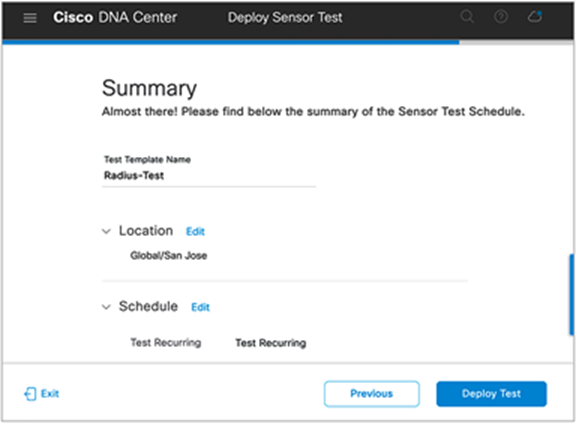
Summary page for scheduling a sensor test
New sensors: Whenever a new sensor is claimed to a floor, the sensor will automatically download and begin running the test deployed on that floor.
Existing sensors: The sensor runs a heartbeat process to Cisco DNA Center every minute through a dedicated backhaul channel (wired or wireless), and Cisco DNA Center informs the sensor of any new or updated sensor tests. Whenever a new or updated sensor test configuration is detected, the sensor will immediately restart the testing.
Note: The sensor test results may not be updated immediately, because the sensor test is updated only after its first interval has passed.
Wireless Sensors dashboard
Description: Cisco DNA Center provides a global view of the wireless sensor test results in an intuitive heatmap view. This view allows you to determine potential issues and performance problems from an end-device perspective.
1. Open the hamburger menu and click Assurance and then Wireless Sensors.
2. View the Wireless Sensors dashboard for test results a couple of minutes after the first round of testing has completed (Figure 89).
3. Optional SSID and band filter: To filter the Wireless Sensors dashboard to show only data for specific sites, click the Multiple Sites button in the top right corner of the screen and select a site (Figure 89).
4. Optional site hierarchy filter: To filter the Wireless Sensors dashboard to show only data from a specific band or SSID, click the Filter button in the top right corner of the screen and make a selection (Figure 89).
5. Optional network time travel: Like all Assurance pages on Cisco DNA Center, the Wireless Sensors dashboard provides the ability to view data back in time for up to 14 days. You can do so either by clicking the date, which provides a drop-down menu that allows you to specify the date and time to view, or by clicking the left and right arrows to the right of the time bar (Figure 89).
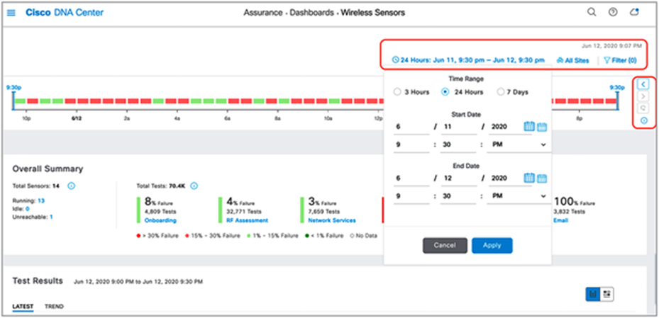
Wireless Sensors dashboard
Overall Summary dashlet: The purpose of this dashlet is to provide numerical statistics regarding the number of tests run and the number that failed.
1. Click each of the test types within the heatmap (Onboarding, RF Assessment, Network Services, Performance, App Connectivity, and Email) to see a drilled-down view of the test results (Figure 90).
Test Results dashlet: The purpose of this dashlet is to provide users with a visual breakdown of the test results and the reason why they occurred.
2. The top half of the Test Results dashlet displays a summary of the test results (Figure 90).
3. To filter the insights by specific locations and/or tests, click the Sites and All Tests drop-down menus to make a selection (Figure 90).
4. View the heatmap in the bottom half of the Test Results dashlet to visualize the sensor test breakdown for each configured test (Figure 90).
Note: The heatmap is categorized based on test category and location where the test was run. The heatmap is also always sorted by worst to best result, which enables you to easily interpret the most problematic areas within the network.
5. To search and filter the heatmap, type a location or sensor name in the search bar located above the heatmap (Figure 90).
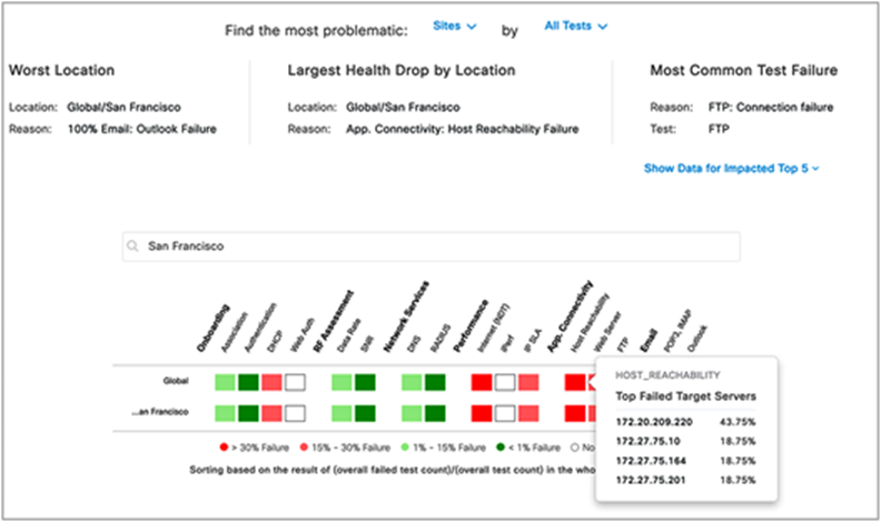
Wireless Sensors dashboard Test Results dashlet
Note: Hovering your cursor over the server-based test type heatmaps will display the Top Failed Target Servers (up to 5). This is not applicable to non-server-based tests.
6. To replace the entire heatmap with a dedicated insights card view, click the rightmost button in the top right corner of the Test Results dashlet (Figure 91).
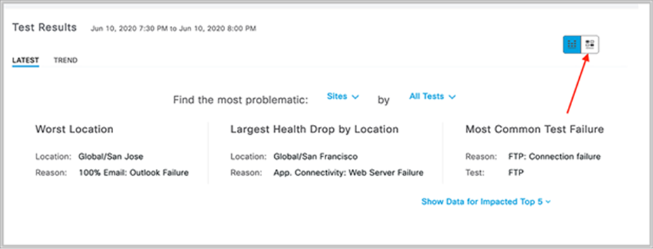
Test Results Insights View button
7. Observe that the page has changed into an insights view (Figure 92).
8. Just as in the heatmap view, to filter the insights by specific site locations and/or tests, click the Sites and All Tests drop-down menus to make a selection (Figure 92).
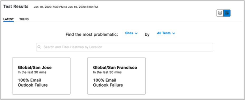
Test Results insights view
The color-coded thresholds group the failed cases into certain percentage ranges and are indicated by four different colors (Figure 93).
9. To customize the color-coded thresholds, click the pen button on the bottom right of the Overall Summary dashlet, make your change, and then click Apply (Figure 93).
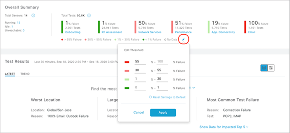
Editing the color-coded thresholds
10. Click the SNR heatmap test result to see a cognitive navigation and drill-down view (Figure 94).
11. From this view, you can easily determine the location, AP, or band in which the failures are occurring by clicking any of the top N filters (Figure 94).
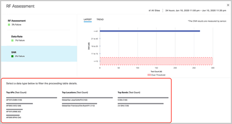
RF Assessment – SNR sensor test drill-down view
Note: Each instance of an RF Assessment test result captures RF performance (RSSI, SNR, transmit/receive [Tx/Rx] rate, Tx retries) during the sensor test. For any test failure case, the drill-down view shows the reason for the failure.
12. Click the Trend button within any of the sensor test drill-down views to see the test data for the past 24 hours (Figure 95).
Note: This period can be configured to be 3 hours or 7 days by clicking the date button at the top of the Wireless Sensors dashboard.
When in the trend chart view, in addition to capturing the success and failure in the network, the chart will display a comparison between the best and worst floors at 30-minute intervals.
13. You can add additional locations to compare by clicking the Add Custom Location button when displaying a trend chart (Figure 95).
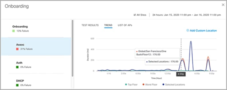
Onboarding – Association sensor test drill-down view
14. Click the DNS heatmap under the Network Services category to switch to a drilled-down view
(Figure 96).
● Observation: In Figure 96, the DNS drill-down test result provides insight into the times at which DNS response times spiked in the past 24 hours.
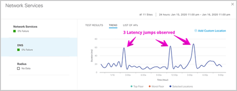
Network Services – DNS sensor test drill-down view
15. Click the Data Rate heatmap under the Network Services category to switch to a drilled-down view (Figure 97).
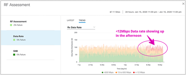
RF Assessment – Data Rate sensor test drill-down view
16. Click the X in the upper right corner of the drill-down view to return to the Wireless Sensors dashboard, then click the Trend button under Test Results to view the 24-hour trend of the heatmap (Figure 98).
● Click the left and right arrows to navigate back or forward in time.

Sensor test result heatmap view and insights view
Note: The heatmap is always shown in sorted fashion, from worst (top) to best (bottom).
17. Click Show Data for Impacted Top 5 to view the worst buildings, largest health drop by buildings, and most common test failure (Figure 99).
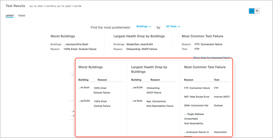
Top failed sensor tests based on location
Sensor 360
The Sensor 360 page displays all the details of a specific sensor device, from device details to sensor test results with heatmap and network time-travel bar, sensor performance trends, and neighbor AP list with floor maps, event logs, and so on.
1. Click the name of a sensor from any page (Wireless Sensors dashboard, Inventory, etc.) to enter the Sensor 360 page (Figure 100).
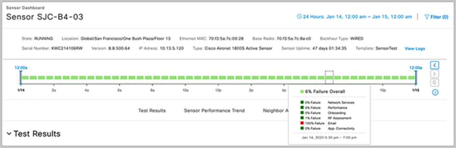
Sensor 360 page
Note: The Sensor 360 page also includes a sensor test results bar based on the test success percentage rate as well as navigation and filter rules similar to the Wireless Sensors dashboard.
1. Scroll down on the Sensor 360 page to view the test results heatmap, which is categorized by AP (Figure 101).
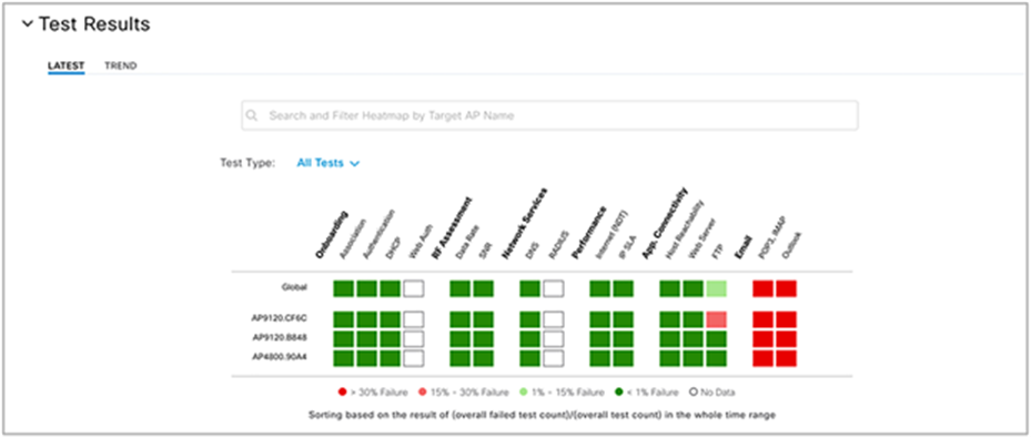
Sensor 360 dashboard
Note: The Sensor 360 heatmap is designed with the same philosophy as the Wireless Sensors dashboard, but the Sensor 360 heatmap provides an additional level of detail by showing the test results per AP.
1. Scroll down further on the Sensor 360 page to see a trend view chart that can be toggled to show different test types and is categorized by top sensor, worst sensor, and current sensor (Figure 102).
2. To add sensor test result data from other locations to this chart (which by default shows only data directly related to this sensor), click the Add Customer Location button and select a site (Figure 102).
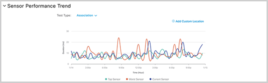
Sensor Performance Trend chart
1. To view all APs neighboring your sensor, scroll down to the Neighbor APs dashlet within the Sensor 360 page (Figure 103).
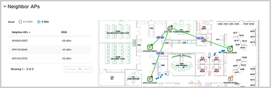
Neighbor APs map view
Note: The Neighbor APs dashlet provides all of the neighbor-scanning AP results and shows a visual relationship between the sensor location and the deployed AP location.
Description: The Issue Settings page depicts the various sensor test failures that can occur when running the sensor tests. This page provides the ability to enable or disable a failure alert as well as to change the priority level.
When two or more sensors on the same floor fail a test in a 30-minute period, the sensor can raise an issue based on the failed test type. These sensor issues are all global issues, meaning that the sensor issue from any floor is escalated and shown in the first Issue dashboard page.
1. To view the sensor-specific issue settings, open the hamburger menu and click Assurance > Issue Settings, then click Sensor for the Device Type to filter the page by sensor issues (Figure 104).
2. Click a sensor Issue Name to toggle its enablement and/or change the priority (Figure 104).
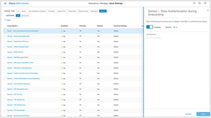
Sensor issue settings
Note: In Cisco DNA Center Software Release 1.3.3 and later, sensor issues can be exported from the Issue dashboard page.
Description: The purpose of this section is to provide you with different methods to troubleshoot any issues seen with your sensor.
Sensor CLI
For troubleshooting the sensor, you can use a console cable, SSH, or a sensor support bundle (described in the next section) that is retrievable from the Sensor 360 page.
The sensor supports SSH; however, the feature is disabled by default. Only limited day-0 SSH is enabled before the sensor is connected to Cisco DNA Center. After the sensor is provisioned in Cisco DNA Center, day-0 SSH is disabled again.
1. To manually reenable SSH on your sensor(s), open the hamburger menu and click Assurance > Manage > Sensors, then select the sensor(s) you would like to enable SSH on. Hover your cursor over the Actions drop-down menu, click Edit SSH, and then enter your desired username and password (Figure 105).
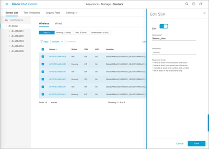
Enabling SSH access on selected sensors
Note: The username and password configured are applied on both SSH and console access.
2. To use any sensor show or config commands, SSH into the device.
Note: Keep in mind that sensor-specific commands have a prefix of show/config dot11.
Sensor command examples:
Sensor-5C98>show dot11 sensor
Heartbeat Show WSA Agent Heartbeat Information
Neighbors Show dot11 sensor neighborlist
prov-ssid Show dot11 sensor provisioning SSID list
route Show dot11 sensor route
scan Show WSA Scanned Information
stats Show dot11 sensor statistics
synthetic Show WSA Synthetic Tests Information
test Show WSA Test Information
wpas-log Show dot11 sensor WPA-Supplicant log
wsa-log Show dot11 sensor WSA log
Event log and sensor support bundle
1. To view sensor troubleshooting logs, navigate to the Sensor 360 page and click View Logs. The Event Log page will show the sensor event logging viewer and provides a downloadable sensor TAC support bundle (Figure 106).
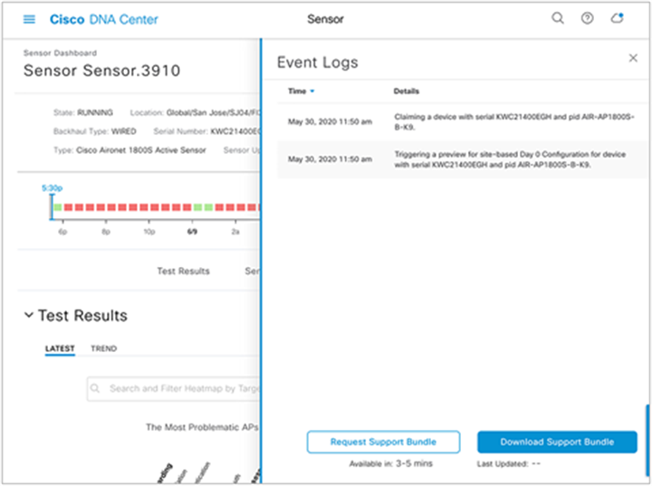
Sensor event logs
The sensor support bundle can be retrieved from the sensor and downloaded to Cisco DNA Center by clicking the Request Support Bundle button. Once the downloadable support bundle becomes available, an updated time under the Download Support Bundle button is displayed.
Note: The support bundle tar file includes all the sensor logging information that is often requested by Cisco TAC, and you can easily attach it to your communication with Cisco TAC.
Reset sensor configuration
1. Option 1 – Factory reset via CLI: To reset the sensor’s configuration to the factory default settings, enter the following command:
clear dot11 sensor
The sensor also provides a hard-reset button on its side panel. This reset button can be used to reset the sensor back to its factory default settings and to erase all configuration, including any static Cisco DNA Center IP addresses.
Option 2 – Factory reset via physical button: To reset the sensor’s configuration to the factory default settings, unplug the sensor from the power source, press and hold the reset button, and plug the sensor back into power, then wait for a minimum of 20 seconds (Figure 107).
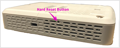
Sensor hard-reset button
Show heartbeat status
A heartbeat between Cisco DNA Center and the sensor occurs every 60 seconds.
1. Run the following command to see the status and last success time of the heartbeat. If there is a failure, confirm connectivity to Cisco DNA Center.
show dot11 sensor heartbeat status
Sensor heartbeat failure condition:
AP70F3.5A7A.5C98#show dot11 sensor heartbeat status
AP70F3.5A7A.5C98# // No response or message
Configuration of the sensor received from Cisco DNA Center through the WLC:
# show dot11 sensor test config
Test Config Received Time: 2019-05-25 22:20:44.912481
{
“advancedConfig”: {
“rssiThreshold”: -75
},
“testConfig”: [
{
“name”: “Onboarding”,
“bands”: “BOTH”,
“scheduleInDays”: 0,
“connection”: “WIRELESS”,
“frequency”: {
“value”: 1,
“unit”: “HOURS”
},
“ssids”: [
{
“username”: “Sensor2”,
“validTo”: 0,
“layer3webAuthsecurity”: null,
“numAps”: 0,
“id”: 0,
“authTypeRcvd”: null,
Results of the sensor tests:
# show dot11 sensor test result all
Test No: 1.1, Name: Onboarding, Time: 2019-05-25 22:52:10.931352
Test Results: {
“macAddress”: “70:f3:5a:78:6b:60”,
“testCompleted”: “no”,
“type”: “DEDICATED”,
“connectivityStats”: {
“wireless”: {
“status”: “SUCCESS”,
“channelWidth”: 20,
“connectionTime”: 8,
“bssid”: “70:69:5A:51:3F:A0”,
“txDataRate”: 78000,
“responseTimesInMillis”: {
“probeRequest”: 53,
“authenticationRequest”: 84,
“handshake”: 1477,
“associationRequest”: 36
},
“snr”: 42,
“rssi”: -40,
“channel”: 1
},
Details for each test that the sensor will execute:
# show dot11 sensor synthetic work list
Group Suite SSID Access Point Radio
===== =================== ===================== ================= =======
1 Global/San Francisco/One Bush St/Flr13:!_1800S_Wired @CorpSSID 70:69:5a:51:3f:a0 802.11b
RSSI Frequency Skip Repeat Min Time Max Time Avg Time
======= ========== ===== ====== ======== ========= ========
-42 dBm 1 HOURS 0 0 01:82.39 01:82.39 01:82.39
Test Name Pass Fail Latest Min Time Max Time Avg Time
==== ============= ==== ==== ====== ======== ======== ========
1 Onboarding 1 0 Pass 00:15.05 00:15.05 00:15.05
2 IpslaSender 0 1 Fail N/A
3 DNS 1 0 Pass 00:05.46 00:05.46 00:05.46
4 Ping 1 0 Pass 00:07.14 00:07.14 00:07.14
5 Speed 1 0 Pass 00:43.30 00:43.30 00:43.30
6 WebServer 1 0 Pass 00:01.14 00:01.14 00:01.14
Details of the sensor’s network assurance statistics:
# show dot11 sensor stats.
## Network Assurance Sensor Statistics ##
WSA Status: Enabled
NA Connectivity: Connected
NA Connectivity I/F: Wired http
NA Server URL: https://10.13.1.100
Auth Type: EAP
HTTP Proxy IP: PROXY_IP
Backhaul SSID: SensorBH
Id-token:
Port: PORT
Total Test Cases Run: 55
Successful Test Cases: 51
Failed Test Cases: 4
Network Assurance 5G Radio Statistics
--------------------------------------
Host Rx K Bytes: 1063804
Host Tx K Bytes: 766328
Unicasts Rx: 1528921
Unicasts Tx: 746511
Broadcasts Rx: 0
Broadcasts Tx: 19
Beacons Rx: 3250
Beacons Tx: 0
Multicasts Rx: 0
Multicasts Tx: 0
CRC errors: 4512
TX retries: 24686
Note:
● Look for Total Test Cases Run, Successful Test Cases, and Failed Test Cases. These results give an indication of how many tests the sensor has performed and the overall status of those tests.
● Observe that the output also includes radio stats as well as whether or not Cisco DNA Center connectivity is enabled.
Show the APs that the sensor can hear and at what signal level:
# show dot11 sensor scan list
Note: Only APs with an RSSI of -75 or higher are tested.
Show the complete logs of all events:
# show dot11 sensor wsa-log
Dump Web Security Appliance (WSA) related debug logs:
# debug wsa debug
Note: Use “term mon” to view the full debug output from the WSA debug.
PnP-related commands (useful during the PnP provisioning phase):
#config dot11 sensor pnp ip 192.168.0.100. // Prime DNAC’s IP address (192.168.0.100) statically
# show pnp info. // Show the pnp agent version.
PI version: 1.8.0.dev20
PD version: 1.5.2.dev2
# show pnp status // Show the pnp status.
Detailed troubleshooting commands output:
# show dot11 sensor heartbeat status
Heartbeat Status: Success, Count: 1787
SSH status: Disabled
Heartbeat Version: 3
Heartbeat Last Success Time: 2019-05-25 23:10:08.567167
Checking wired backhaul config received from Cisco DNA Center:
AP70F3.5A7E.4E98#show dot11 sensor wired-dot1x status
AP70F3.5A7E.4E98#ion": "none", "username": "mohamed", "authType": "dot1x", "eapTlsCertPassPhrase": "none", "useSCEP": "none", "password": "Password123", "eapType": "PEAP-MSCHAPv2"}
Checking status of wired port 802.1X authentication:
AP70F3.5A7E.4E98#show authentication interface wired-port status
key_mgmt=IEEE 802.1X (no WPA)
wpa_state=COMPLETED
address=70:f3:5a:7e:4e:98
Supplicant PAE state=AUTHENTICATED
suppPortStatus=Authorized
EAP state=SUCCESS
selectedMethod=25 (EAP-PEAP)
EAP TLS cipher=ECDHE-RSA-AES256-GCM-SHA384
EAP-PEAPv1 Phase2 method=MSCHAPV2
Changing the log level for the 802.1X process over the wired port:
AP70F3.5A7E.4E98#debug authentication interface wired
debug Wired port 802.1X module debug
error Wired port 802.1X module error
excessive Wired port 802.1X module excessive
info Wired port 802.1X module info
msgdump Wired port 802.1X module msgdump
warning Wired port 802.1X module warning
AP70F3.5A7E.4E98#debug authentication interface wired msgdump
Cisco DNA Center Administrator Guide
Cisco DNA Assurance User Guide 2.1.2.0: Manage Sensors and Sensor-Driven Tests
Solution Guide for Cisco Network Plug and Play
Cisco Aironet Series Console Adapter Cable AIR-CONSADPT= Guide
Configure SCEP for Locally Significant Certificate Provisioning on 9800 WLC