Cisco Catalyst Micro Switches White Paper
Available Languages
Bias-Free Language
The documentation set for this product strives to use bias-free language. For the purposes of this documentation set, bias-free is defined as language that does not imply discrimination based on age, disability, gender, racial identity, ethnic identity, sexual orientation, socioeconomic status, and intersectionality. Exceptions may be present in the documentation due to language that is hardcoded in the user interfaces of the product software, language used based on RFP documentation, or language that is used by a referenced third-party product. Learn more about how Cisco is using Inclusive Language.
Modern network architecture requires a resilient and cost-effective infrastructure for steady, increasing bandwidth needs. Fiber to the office, building, desk, etc. (FTTx) provides the ideal foundation for next-generation access network infrastructure. FTTx extends the fiber infrastructure to the end users, accommodating for modern network infrastructure needs, such as growing network bandwidth, extended reachability, and security.
The Cisco Catalyst Micro Switches have been designed and engineered for FTTx deployments and decentralized network designs for enterprises, healthcare, airports, universities, and more.
Why FTTx?
● Lower energy consumption and greater power efficiency
● Easier to install and compact form factors
● Ideal long-distance reachability
● More secure medium and greater operational safety
● Easier space redistribution
The new Catalyst Micro Switches are ultra-small, managed, Gigabit Ethernet, Power over Ethernet Plus (PoE+), fanless switches, purpose built for FTTx deployments and distributed network designs. These switches consist of wall jack and desktop-based models that offer flexible mounting options, opening up a variety of network designs and connectivity opportunities. They are deployed right next to the end devices (laptops, cameras, IP phones, etc.), with the uplinks connecting directly to the Main Distribution Frame (MDF)—eliminating the need for an Intermediate Distribution Frame (IDF) and, in turn, reducing real estate costs, power consumption, and cable infrastructure costs.
The Catalyst Micro Switches are 4-port 1 Gigabit Ethernet (1G) switches with whisper-quiet, fanless operation. They are based on a custom merchant Application-Specific Integrated Circuit (ASIC) with an internal ARM CPU architecture. The platform runs the Cisco IOS Classic operating system, which enables the switch to support the LAN Lite feature set.
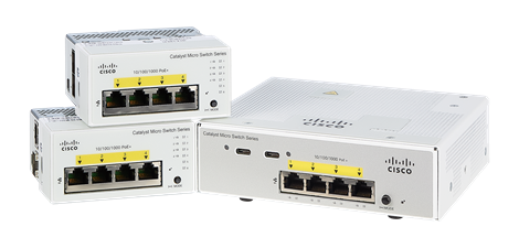
Cisco Catalyst Micro Switches
With both wall jack and desktop models for deployment flexibility, the micro switches offer a variety of general-purpose and specific cable duct deployment use cases.
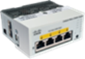
Wall jack switches
CMICR-4PC: Catalyst Micro Switch with four 1G ports, one 1G copper uplink, and one 1G SFP uplink
CMICR-4PS: Catalyst Micro Switch with four 1G ports and two 1G SFP uplinks
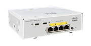
Desktop switch
CMICR-4PT: Catalyst Micro Switch with four 1G ports, one 1G copper uplink, one 1G combo uplink, and two USB-C Cisco UPOE ports
Table 1. Comparison of wall jack and desktop switch models
|
|
Wall jack models |
Desktop model |
| Micro switch model |
|
|
| Uplinks |
2x 1G SFP or 1x 1G RJ-45 and 1x 1G SFP |
1x 1G RJ-45 and 1x 1G combo |
| Downlinks |
4x 1G |
4x 1G |
| Dimensions (WxHxD) |
90 x 45 x 79 mm (3.54 x 1.77 x 3.11 in.) |
153 x 45 x 133 mm (6.02 x 1.77 x 5.24 in.) |
| PoE budget (PoE+) |
60W |
120W |
The Cisco Catalyst Micro Switches come with a single external power adapter supporting AC power input. The wall jack switches are designed in such a way that they also support an industry-standard 3-pin power adapter by using a special 3-pin-to-2-pin cable assembly. The industry-standard power supply can be enabled using a single command, as shown in the figure below.
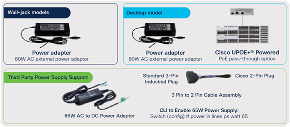
Powering options
The desktop-based model can also be powered via a Cisco UPOE+ powered PoE pass-through option. The PoE pass-through enables the micro switch to draw Cisco UPOE from an upstream switch via the copper uplink and, further, to pass PoE+ to the end peripherals. These switches are ideal for wiring-constrained and space-constrained deployments where it would be difficult to install an electric circuit or power adapter. The PoE pass-through option can also be used alongside an auxiliary power adapter to provide additive PoE and power redundancy.
Table 2. PoE pass-through budget
| Input power (W) |
Pass-through power (W) |
|
| PoE Uplink |
Power adapter |
|
| 60 |
|
29 |
| 90 |
|
46 |
|
|
80 |
62 |
| 15 |
80 |
62 |
| 30 |
80 |
62 |
| 60 |
80 |
99 |
| 90 |
80 |
120 |
The micro switches are capable of PoE+ on all downlinks to power newer smart devices with specific power needs, and also make power easily accessible for hard-to-reach remote devices, such as outdoor cameras, sensors, detectors, and many other PoE-capable devices. The desktop-based switches come with two USB-C ports which are capable of providing UPOE on the ports with a combined maximum budget of 60W PoE, ideal for powering and charging tablets, phones, etc. The micro switches are integrated with the PoE features listed below to build a robust, low-voltage infrastructure ideal for crucial sensors and IoT endpoints.
● 2-event classification: With 2-event classification, the micro switches provide faster power allocation by negotiating power at the physical layer level and essentially providing power to the Powered Device (PD) within 1 to 2 seconds.
● Perpetual PoE: Perpetual POE provides uninterrupted power to the connected PD, even when the Power Sourcing Equipment (PSE) switch is booting.
● Fast PoE: When Fast PoE is enabled on a particular port, the micro switch remembers the last power drawn from a particular PSE port and switches the power on the moment AC power is plugged in (within 15 to 20 seconds of the switch powering on) without waiting for Cisco IOS to boot up. The switch, upon recovery after a power failure, provides power to the connected endpoint devices within a short duration—even before the Cisco IOS forwarding starts up.
The Catalyst Micro Switches provide installation simplicity by offering flexible mounting options. They provide multiple mounting options, including wall mount, C-rail duct mount, DIN rail mount, and desktop or bottom mount, depending on the model and deployment.
The wall jack switches support direct mount (that is, the switches conform to the MOSAIC 45x45 mm industrial standard) and can be mounted into compliant ducts without any accessories.
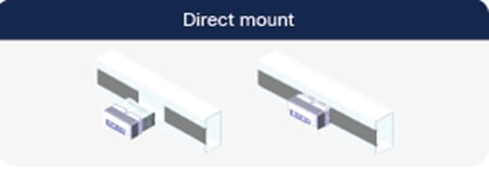
Direct mount configuration
The wall jack switches are designed in a such a way that they reuse existing third-party mounting brackets and plastic ducts for new micro switch installations. The figure below illustrates the supported mounting configurations for the wall jack models.
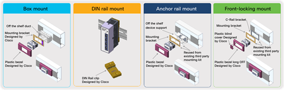
Wall jack switch mounting configurations
The desktop-based switches allow for mounting on a tabletop or bottom and wall mounting. These switches are best suited for desktop powering solutions by extending the fiber to the desktop. The figure below shows the supported mounting configurations for the desktop-based models.
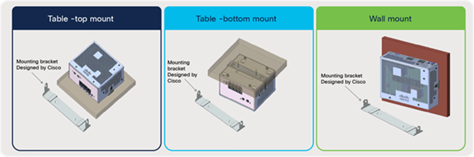
Desktop switch mounting configurations
The table below highlights the accessories designed by Cisco and accessories that can be used from a third-party preexisting mounting kit for each mounting deployment.
Table 3. Mounting accessories
| Unit |
Mounting option |
Accessories from Cisco |
Parts from third-party |
| Wall jack |
Anchor rail mount |
Plastic bezel |
Mounting bracket and Plastic duct |
| Front-locking mount |
Plastic bezel |
Mounting and C-rail bracket |
|
| Box mount |
Plastic bezel and mounting bracket |
Plastic duct |
|
| DIN rail mount |
DIN rail dip |
NA |
|
| Desktop |
Table top, Table bottom, Wall mount |
Mounting bracket |
NA |
The Cisco Catalyst Micro Switches enable distributed network architecture designs, opening up a variety of connectivity opportunities and network designs. The distributed network allows the micro switches to be installed right next to the end users, extending the fiber infrastructure to end peripherals. This in turn helps optimize space by eliminating the requirement of IDF, increase power efficiency, and provide local failure and security control. The micro switches support the three primary deployment architectures described below.
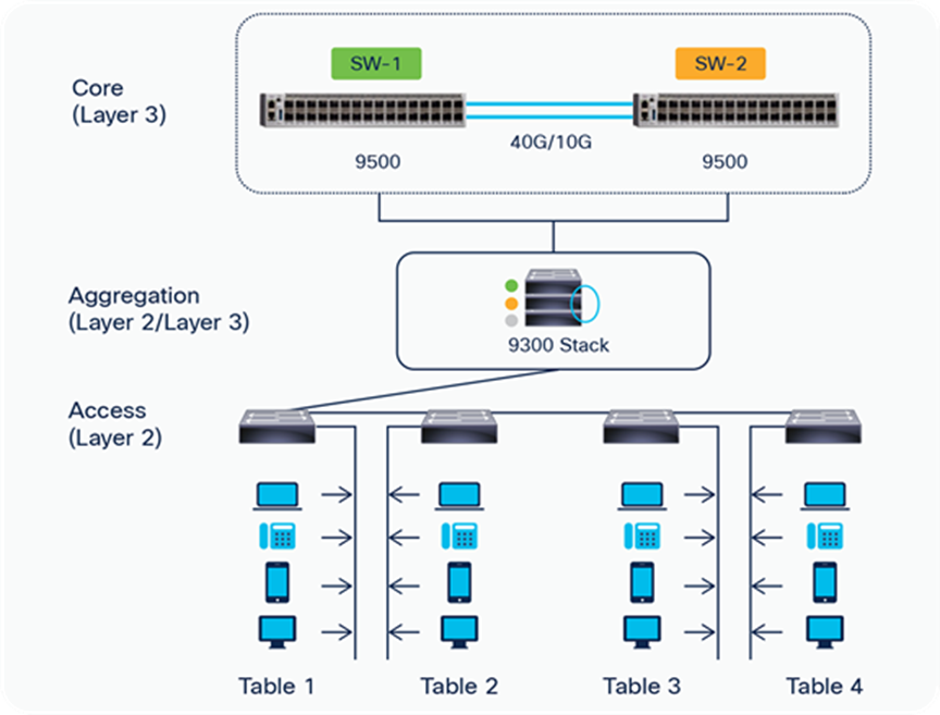
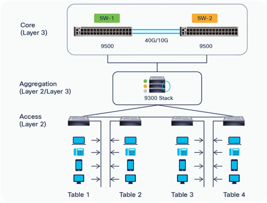
Star network topology: One of the most common network topologies, a star topology involves connecting each micro switch individually to an upstream/aggregation switch via a dedicated link/cable. This is a high-performing network architecture, since each micro switch gets dedicated bandwidth from the upstream/ aggregation switch and adding or removing a micro switch has no impact on the rest of the network.
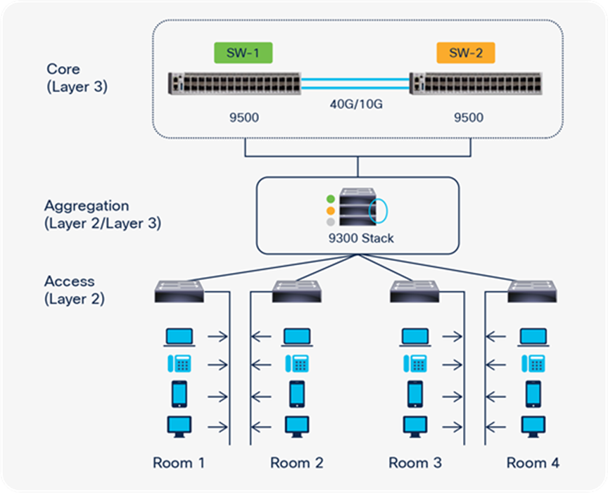
Star network topology
Daisy chain network topology: This is the simplest network topology, wherein one of the micro switches connects to the upstream/ aggregation switch and the rest of the micro switches are connected to one another in a series, for a linear architecture. This topology requires fewer ports on the aggregation/ upstream switch and runs shorter cables per endpoint. Considering that the overall bandwidth for the link is 1G, we recommend connecting a maximum of five switches using the daisy chain architecture.
Daisy chain network topology
Ring network topology: The most resilient network architecture, the ring topology involves connecting each micro switch to two switch neighbors in a ring formation. This topology enables maximum data redundancy due to alternate path availability. The micro switches connected in this network configuration can work with Resilient Ethernet Protocol (REP) and Spanning Tree Protocol (STP) for ring operation, and a maximum of five switches are recommended.
Ring network topology
The Catalyst Micro Switches provide a range of security features to limit access to the network and mitigate threats. The switches come integrated with a First-Hop Security (FHS) feature set, which enables better IPv4 link security and management over Layer 2 links.
The following supported FHS features secure the protocols and help build a secure endpoint to mitigate some common Layer 2 attacks such as Address Resolution Protocol (ARP) poisoning, Dynamic Host Configuration Protocol (DHCP) rogue server attack, etc.
● Port security: The port security feature protects the micro switches from being flooded with unknown MAC addresses by limiting the number of MAC addresses learned per port.
● DHCP snooping: The DHCP snooping feature validates DHCP messages received from untrusted sources and filters out invalid messages.
● Dynamic ARP inspection: The dynamic ARP inspection feature helps to intercept, log, and discard ARP packets with invalid MAC address to IP address bindings.
The impact on enterprise network access from wireless network access, mobility, and Bring Your Own Device (BYOD) has been transformative over time, and it is necessary to keep the network both operational and secure with these evolving network trends. To prevent unauthorized users from getting network access, the micro switches have a built-in feature set (such as IEEE 802.1X authentication, port Access Control List [ACL], and a private VLAN [PVLAN] edge protected switch port). The micro switches also support 802.1X monitor mode implementation, which helps ensure that network access services are not impacted while the end-to-end 802.1X configuration is validated for any new endpoint; the administrator also gains visibility into the failed and passed authentications and can take action accordingly.
In terms of hardware security, the micro switches come with built-in trustworthy systems support, which helps ensure that the hardware and software of the device cannot be tampered with and that the product is an authentic Cisco product. In addition, since the desktop model can be installed on workstations or tabletops, it comes with a Kensington security slot that attaches to a stationary object such as a table via a cable to secure the device in public environments.
The Cisco Catalyst Micro Switches support Cisco DNA Center for simplified management using a centralized dashboard. Cisco DNA Center provides access to base automation, assurance, and design capabilities to administer and provision hundreds of switches in a very short duration of time from a single user interface. The micro switches with Cisco DNA Center support the following capabilities to ease the onboarding and day-to-day management activities.
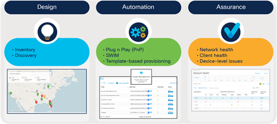
Cisco DNA Center features for managing the micro switches
Design: The design features of Cisco DNA Center enable you to design your network for consistent configurations by device and by site. Physical maps and logical topologies help provide a quick visual reference. Device configurations by site can be consolidated in a “golden image” that can be used to automatically provision new network devices.
Automation: The automation capabilities of Cisco DNA Center significantly simplify the onboarding of the micro switches. Plug-and-play deployment and Software Image Management (SWIM) features reduce device installation and upgrade times from hours to minutes and bring new switches online with plug-and-play ease.
Assurance: The assurance capabilities of Cisco DNA Center enable you to monitor end-to-end network performance. The clean and simple dashboard shows detailed network health and flags issues about each node. Guided remediation automates issue resolution to keep your network performing optimally. The outcome is a consistent experience and proactive optimization of your network, with less time spent on troubleshooting tasks.
The micro switches can also be monitored via a third-party monitoring station using a standard Simple Network Management Protocol (SNMP) v3, Secure Shell (SSH), and HTTPS implementation. Configuration management for smaller deployments is simplified further by the ability to store the configuration and image on a micro SD card, where it is secured against unauthorized access and disabled by default via the Command-Line Interface (CLI). The switches are capable of booting from the configuration and image present on the micro SD card to speed recovery and ease onboarding for smaller deployments.
The Catalyst Micro Switches can be used as Cisco Software-Defined Access (SD-Access) extended nodes to integrate wired and IoT endpoints into the Intent-Based Networking (IBN) infrastructure. Cisco DNA Center manages extended nodes as part of the SD-Access solution, and these nodes enjoy all the operational benefits of Cisco DNA Center, including consistent segmentation and policy-based access. The micro switches are capable of providing macro-segmentation between the endpoints. The figure below illustrates the suggested topologies for deploying micro switches in an SD-Access architecture. The micro switches can be connected either standalone or in a ring architecture to a single edge node extending single or multiple VLANs.
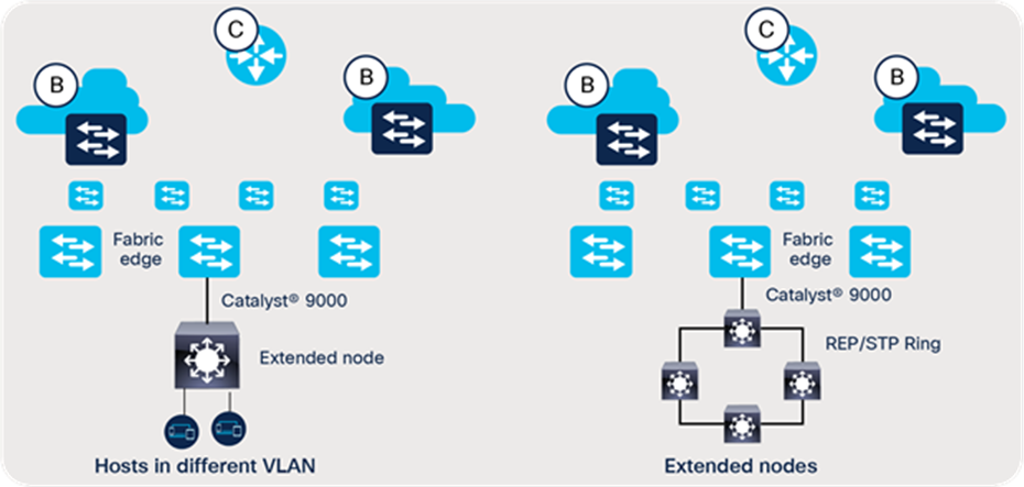
SD-Access extended node network topologies
The new Cisco Catalyst Micro Switches are purpose built for a decentralized network architecture, offering significant advantages such as power efficiency, space optimization, and lower infrastructure cost. The switches have an ultra-small form factor with a fanless design and flexible mounting and powering options, opening up a variety of network designs and connectivity solutions.